EP1274186A2 - Control system using a mini slot signal in a passive optical network - Google Patents
Control system using a mini slot signal in a passive optical network Download PDFInfo
- Publication number
- EP1274186A2 EP1274186A2 EP02011195A EP02011195A EP1274186A2 EP 1274186 A2 EP1274186 A2 EP 1274186A2 EP 02011195 A EP02011195 A EP 02011195A EP 02011195 A EP02011195 A EP 02011195A EP 1274186 A2 EP1274186 A2 EP 1274186A2
- Authority
- EP
- European Patent Office
- Prior art keywords
- state
- mini slot
- signal
- onu
- child
- Prior art date
- Legal status (The legal status is an assumption and is not a legal conclusion. Google has not performed a legal analysis and makes no representation as to the accuracy of the status listed.)
- Granted
Links
Images





Classifications
-
- H—ELECTRICITY
- H04—ELECTRIC COMMUNICATION TECHNIQUE
- H04J—MULTIPLEX COMMUNICATION
- H04J3/00—Time-division multiplex systems
- H04J3/02—Details
- H04J3/14—Monitoring arrangements
-
- H—ELECTRICITY
- H04—ELECTRIC COMMUNICATION TECHNIQUE
- H04J—MULTIPLEX COMMUNICATION
- H04J3/00—Time-division multiplex systems
- H04J3/16—Time-division multiplex systems in which the time allocation to individual channels within a transmission cycle is variable, e.g. to accommodate varying complexity of signals, to vary number of channels transmitted
- H04J3/1694—Allocation of channels in TDM/TDMA networks, e.g. distributed multiplexers
-
- H—ELECTRICITY
- H04—ELECTRIC COMMUNICATION TECHNIQUE
- H04Q—SELECTING
- H04Q11/00—Selecting arrangements for multiplex systems
- H04Q11/0001—Selecting arrangements for multiplex systems using optical switching
- H04Q11/0062—Network aspects
-
- H—ELECTRICITY
- H04—ELECTRIC COMMUNICATION TECHNIQUE
- H04Q—SELECTING
- H04Q11/00—Selecting arrangements for multiplex systems
- H04Q11/0001—Selecting arrangements for multiplex systems using optical switching
- H04Q11/0062—Network aspects
- H04Q11/0067—Provisions for optical access or distribution networks, e.g. Gigabit Ethernet Passive Optical Network (GE-PON), ATM-based Passive Optical Network (A-PON), PON-Ring
-
- H—ELECTRICITY
- H04—ELECTRIC COMMUNICATION TECHNIQUE
- H04Q—SELECTING
- H04Q11/00—Selecting arrangements for multiplex systems
- H04Q11/0001—Selecting arrangements for multiplex systems using optical switching
- H04Q11/0062—Network aspects
- H04Q2011/0064—Arbitration, scheduling or medium access control aspects
-
- H—ELECTRICITY
- H04—ELECTRIC COMMUNICATION TECHNIQUE
- H04Q—SELECTING
- H04Q11/00—Selecting arrangements for multiplex systems
- H04Q11/0001—Selecting arrangements for multiplex systems using optical switching
- H04Q11/0062—Network aspects
- H04Q2011/0086—Network resource allocation, dimensioning or optimisation
Definitions
- This invention relates to a maintenance signal corresponding to a mini slot signal in a slot according to international standard ITU-T G.983.1 regulating a physical interface in a PON (Passive Optical Network) and a method for controlling a state in dynamic bandwidth assignment (DBA) for upstream by using the mini slot signal.
- ITU-T G.983.1 regulating a physical interface in a PON (Passive Optical Network)
- DBA dynamic bandwidth assignment
- Fig. 3 illustrates an example of a configuration of a system in the PON including a DBA function, in which an OLT (optical line terminator - parent station) 101 and a plurality of ONU's (optical network terminating units - child stations) 102-104 are coupled to by a star coupler 105.
- Fig. 4 illustrates a downstream frame format 151 and an upstream frame format 152 in the PON according to international standard ITU-T G.983.1 regulating a physical interface in the PON according to the related art.
- Fig. 4 illustrates a downstream frame format 151 and an upstream frame format 152 in the PON according to international standard ITU-T G.983.1 regulating a physical interface in the PON according to the related art.
- FIG. 5 shows a state transition table for managing a state of an individual ONU dealing unit in the OLT according to international standard ITU-T G.983.1 regulating an operation by the OLT for controlling starting and halting of an individual ONU.
- Fig. 6 illustrates an example of a condition of detecting and resetting according to international standard ITU-T G.983.1 related to a maintenance signal provided for each of the ONU's indicating a state of receiving an ATM (asynchronous transfer mode) cell and PLOAM (Physical Layer Operation Administration and Maintenance) cell in an upstream frame in the OLT.
- Fig. 7 illustrates a format of a mini slot in a slot according to international standard ITU-T G.983.1 related to the upstream frame.
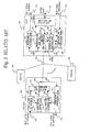
- the OLT 101 includes an individual ONU dealing unit 106B, a generator 107 for downstream frame, a controller 108 for upstream band, a DBA controller 109B, a terminator 110 of upstream frame, and a terminator 111 of mini slot.
- the ONU 103 includes a terminator 112 of downstream frame, a detector 113 for upstream band, a cell buffer 114 for upstream, a monitor 115 for buffer state, and a cell generator 116 for upstream.
- the OLT 101 receives a main signal 122 of downstream including an ATM cell, and generates a frame signal 124 of downstream by the generator 107 for downstream frame.
- the generator 107 for downstream frame receives control information 126 on the ONU from the individual ONU dealing unit 106B and information 125 on an upstream band from the controller 108 for upstream band, generates a PLOAM cell of downstream, and inserts the generated PLOAM cell into the frame signal 124 of downstream.
- the individual ONU dealing unit 106B exchanges information on each of the ONU's as a control signal 121 with an external operation system.
- a frame signal 129 of upstream sent from each of the ONU's is terminated.
- a regular cell is terminated by the terminator 110 of upstream frame, and a mini slot is terminated by the terminator 111 of mini slot.
- the terminator 110 of upstream frame detects a PLOAM cell of upstream when the regular cell is terminated, and notifies the individual ONU dealing unit 106B of control information 130 on the ONU corresponding to the PLOAM cell.
- the terminator 110 of upstream frame outputs a main signal 123 of upstream when the ATM cell besides the PLOAM cell is detected.
- State information 131 on a cell buffer for upstream of an ONU corresponding to the mini slot terminated by the terminator 111 of mini slot is sent to the DBA (Dynamic Bandwidth Assignment) controller 109B. Further, state information 127 corresponding to the individual ONU and information 132 on the upstream band is sent to the DBA controller 109B and the controller 108 for upstream band, and an operation of dynamic bandwidth assignment (DBA) for upstream is performed.
- DBA Dynamic Bandwidth Assignment
- the ONU 103 extracts a main signal 141 of downstream including an ATM cell directed to the ONU 103 as the terminator 112 of downstream frame terminates a downstream frame signal 143. Particularly, a PLOAM cell 144 of downstream is extracted, and control information 145 on outputting the upstream cell is output to the cell generator 116 for upstream by the detector 113 for upstream band.
- a main signal 142 of upstream including the ATM cell is maintained in the cell buffer 114 for upstream once, and read out as information 146 on the cell based on an instruction from the cell generator 116 for upstream.
- a header is attached to the information 146 on the cell by the cell generator 116 for upstream, and the information 146 on the cell is output as a frame signal 149 of upstream.
- Information 147 on the cell buffer 114 for upstream is always monitored by the monitor 115 for buffer state, and output to the cell generator 116 for upstream as information 148 on a buffer state for mapping in the mini slot.
- the frame format 151 of downstream includes 56 ATM cells in a fixed length of 53 bytes located consecutively.
- the cells, the first cell and the 29th cell are PLOAM cells for monitoring and controlling between the OLT and the ONU.
- the upstream frame format 152 includes 53 cells of 56 bytes. 56 bytes include 3 bytes of overhead and 53 bytes of ATM cells. It is also possible that the PLOAM cell is provided in an ATM cell at an arbitrary position.
- the OLT 101 manages a state of each of the ONU's 102-104 connected to the PON individually based on a state transition table of the individual ONU dealing unit in the OLT illustrated in Fig. 5.
- FIG. 5 columns arranged horizontally illustrate an initial state (OLT-IDV1), a state of measuring delay (OLT-IDV2), and an operation state (OLT-IDV3).
- the initial state (OLT-IDV1) illustrates a state of initializing a start operation temporally as a corresponding ONU is not started or there is a certain failure.
- the state of measuring delay (OLT-IDV2) illustrates a state of measuring a delay in transmission of a cell due to a transmission distance between the OLT and the ONU.
- the operation state (OLT-IDV3) illustrates a state of transmitting an upstream cell in timing in which the ONU compensated the delay in upstream by measuring the delay in the transmission of the cell due to the transmission distance and informing the ONU of information on the measured delay by the OLT.
- n means the number of ONU.
- Instructing to start measuring delay (n) is an instruction issued in the initial state when the ONU is started.
- Completing measuring delay (n) is issued to the ONU which is measured the delay in the state of measuring delay when the delay is measured normally.
- Detecting abnormality of measuring delay (n) is issued to the ONU which is measured the delay in the state of measuring delay when the delay is not measured normally.
- Each of the maintenance signals is a signal detected and reset in the operation state in each of conditions illustrated in Fig. 6.
- the third ONU which is in the initial state (OLT-IDV1) receives a state transition event of instructing to start measuring delay (n), and a state transits to the state of measuring delay (OLT-IDV2).
- OLT-IDV2 state transition event of instructing to start measuring delay
- OLT-IDV3 state transits to the operation state
- OLT-IDV1 state transition event of detecting abnormality of measuring delay (n) is received, and the state transits to the initial state (OLT-IDV1).
- the individual ONU dealing unit in the OLT corresponding to the third ONU which is in the operation state begins to monitor each of the maintenance signals (LOSi, CPEi, LCDi, OAMLi, LOAi, R-INHi) corresponding to the third ONU.
- the state transits to the initial state (OLT-IDV1).
- the individual ONU dealing unit in the OLT corresponding to the third ONU which is not in the operation state is started to go back to the operation state by a state transition event of instructing to start measuring delay (n) which occurs regularly.
- the ONU which is in the operation state communicates by using the downstream frame format 151 and the upstream frame format 152 as illustrated in Fig. 4.
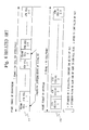
- a certain phase of a cell there is a case in which a certain cell is used in a slot 162 of an upstream frame 161 illustrated in Fig. 7 and the ONU sends a mini slot signal 163.
- the OLT sets a phase of an upstream cell in the slot 162
- a plurality of ONU's send the mini slot signals 163 in the slot 162.
- the mini slot signals 163 sent from the plurality of ONU's are controlled by the OLT for preventing collision.
- the OLT sets a phase (offset) from a beginning of the slot 162 and information on length of the mini slot signal 163 corresponding to the ONU in the ONU's individually.
- the dynamic bandwidth assignment (DBA) for upstream is performed by using a mini slot signal including a function equivalent to an individual communication channel besides a regular cell from the plurality of ONU's to the OLT.
- a mini slot signal including a function equivalent to an individual communication channel besides a regular cell from the plurality of ONU's to the OLT.
- each of the ONU's informs the OLT of a buffer state of upstream in the ONU.
- the OLT extracts a content of the mini slot signal, and detects a buffer state in each of ONU's.
- ONU#1 shows a cell sent from a first ONU in a band allocated for the first ONU.
- ONU#2 and ONU#3 also show cells.
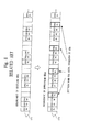
- all of the ONU's informs the OLT of a cell buffer state for upstream by using the mini slot signal constantly. For example, when it is judged that the cell buffer state for upstream in the first ONU exceeds a threshold value of the buffer determined by the OLT, the OLT temporally allocates a bandwidth wider than a present bandwidth of the upstream band. Therefore, the arrangement 171 of the cells is changed to an arrangement 172 of the cells in the upstream frame.
- the arrangement 172 indicates that an utilized upstream band is allocated to the first ONU.
- a control method using the mini slot signal in the slot according to international standard ITU-T G.983.1 regulating the physical interface in the PON according to the related art only describes a configuration of a format of the slot. There isn't any definition about maintenance signal by the mini slot. There isn't also any definition of using the mini slot for DBA request, and of controlling method for the mini slot. Therefore, it is impossible to monitor and control a receiving state of the regular cell and the mini slot signal individually. For example, when the maintenance signal of the regular cell illustrated in Fig. 6 is used for the mini slot signal, even if only the mini slot signal operates in failure, it is judged as a state transition of the regular cell of the ONU by the individual ONU dealing unit 106B in the OLT illustrated in Fig. 5, and whole communication is suspended.
- Fig. 9 illustrate a state of failure of the mini slot signal in the slot 181.
- the ONU misjudges a phase of transmission of the mini slot signal, there is a possibility of the collision with another cell or mini slot signal sent from another ONU, located before and after the mini slot signal.
- there is no method of individually controlling the mini slot signal in failure by misjudging the phase of transmission a state of the collision is maintained, and transmission of the cell or mini slot from another ONU is prevented continuously.
- the assignment of the upstream band to the ONU is controlled dynamically by using the mini slot signal, communication by all of the other ONU's is prevented by the failure of the mini slot signal of one ONU as in this case.
- DBA dynamic bandwidth assignment
- a control system uses a mini slot signal in a passive optical network.
- the passive optical network includes a parent station (OLT: optical line terminal) and a plurality of child stations (ONU: optical network terminating unit) for transmitting an upstream frame and a downstream frame each other.
- the parent station includes an individual ONU dealing unit for providing a maintenance signal corresponding to each of the plurality of child stations concerning on a mini slot and controlling state transition in dynamic bandwidth assignment (DBA) for each of the plurality of child stations by using the maintenance signal concerning on the mini slot.
- DBA dynamic bandwidth assignment
- the parent station instructs a corresponding child station to transit to a state beside an operation state when one of failures of receiving an effective mini slot signal from the child station and receiving a mini slot in a correct phase is detected as a maintenance signal concerning on the mini slot signal.
- a control method uses a mini slot signal in a passive optical network.
- the passive optical network includes a parent station (OLT: optical line terminal) and a plurality of child stations (ONU: optical network terminating unit) for transmitting an upstream frame and a downstream frame each other.
- OLT optical line terminal
- ONU optical network terminating unit
- the control method provides a maintenance signal corresponding to each of the plurality of child stations concerning on a mini slot and controls state transition in dynamic bandwidth assignment (DBA) for each of the plurality of child stations by using the maintenance signal concerning on the mini slot by an individual ONU dealing unit in the parent station.
- DBA dynamic bandwidth assignment
- the control method instructs a corresponding child station to transit to a state beside an operation state by the parent station when one of failures of receiving an effective mini slot signal from the child station and receives a mini slot in a correct phase is detected as a maintenance signal concerning on the mini slot signal.
- FIG. 1 A maintenance signal for a mini slot signal and an operation of this invention are explained by Fig. 1 and Fig. 2.
- Fig. 1 as types of the maintenance signal, failure of receiving a mini slot signal (LOS-Di) I51, out-of-synchronization of the mini slot signal (LCD-Di) I52, error in a phase of receiving the mini slot signal (CPE-Di) I53, error in a block of the mini slot signal (ERR-Di) I54 are provided besides the maintenance signal of the regular cell.
- Fig. 2 shows a state transition table for corresponding the maintenance signals for the mini slot signal described in Fig. 1 to a state of controlling the ONU individually by the OLT.
- An operation of this invention is explained by Fig. 1 and Fig. 2.
- an individual ONU dealing unit 106 and a DBA controller 109 which are provided additionally, manage and control by performing the dynamic bandwidth assignment (DBA) for upstream corresponding to each of the ONU's individually.
- DBA dynamic bandwidth assignment
- the individual ONU dealing unit 106 and the DBA controller 109 provide three states, i.e., halt state of DBA (DBA-ST1) S1, wait state of DBA operation (DBA-ST2) S2 and DBA operation state (DBA-ST3) S3 arranged horizontally in Fig. 2 as states of controlling the DBA by using the mini slot signal. Further, as state transition events for changing the states, the state transition events are regulated sequentially from the top to the bottom in Fig. 2.
- Event I1 of detecting the instruction for halting the DBA function for instructing if a function of the DBA is operated, and event I2 of detecting a state in which the OLT controls the ONU individually and one of maintenance signals IDV1, IDV2, LOSi, LCDi, CPEi, OAMLi, LOAi, and R-INHi are provided.
- event I3 of detecting IDV3 without detecting the instruction of halting the DBA function and event I4 of recognizing an ONT-DBA type are provided.
- an event I5 of detecting CPE-Di which is a maintenance signal of the mini slot signal is provided. A number of a child station of 1-n is shown as i.
- an O/E receiver for dealing ONUi in the OLT does not receive an effective optical signal in an expected period for receiving an upstream mini slot signal n times consecutively, it is judged that interruption of receiving a mini slot signal (LOS-Di) is detected.
- the OLT receives an optical signal matched with its slot GRANT in the DBA operation state (DBA-ST3), it is judged that the interruption of receiving the mini slot signal (LOS-Di) is reset.
- the receiver for dealing ONUi in the OLT receives an ineffective delimiter n times consecutively, it is judged that out-of-synchronization of the mini slot signal (LCD-Di) is detected.
- a mini slot signal in a correct phase is received in the DBA operation state (DBA-ST3), it is judged that the out-of-synchronization of the mini slot signal (LCD-Di) is reset.
- the individual ONU dealing unit 106 in the OLT relates a state of controlling the ONU individually with a maintenance signal for the mini slot signal.
- the DBA controller 109 controls dynamic bandwidth assignment (DBA) for upstream corresponding to each of ONU's individually.
- the OLT performs the dynamic bandwidth assignment (DBA) for upstream based on the state transition table illustrated in Fig. 2.
- DBA-ST1 a state before detecting an instruction of stopping DBA function
- IDV3 operation state
- DBA-ST2 the individual ONU dealing unit 106 instructs the ONU to be in the state transits to the wait state of DBA operation
- the individual ONU dealing unit in the wait state of DBA operation recognizes an ONT-DBA type by ITU-TG.983.2, the slot GRANT is set, and the state transits to the DBA operation state (DBA-ST3).
- a certain maintenance signal LOSi, LCDi, CPEi, OAMLi, LOAi, R-INHi
- the state of the individual ONU dealing unit (n) in the OLT is either IDV1 or IDV2
- the individual ONU dealing unit (n) in the OLT which is the DBA operation state judges that the concerning ONU is not in the operation state.
- setting of the slot GRANT is reset, and the state transits to the halt state of DBA (DBA-ST1). Further, when error in the phase of receiving the mini slot signal (CPE-Di (n)) which is a maintenance signal concerning on the mini slot signal is detected, setting of the slot GRANT is reset, and the state transits to the wait state of DBA operation (DBA-ST2).
- CPE-Di (n) which is a maintenance signal concerning on the mini slot signal
- DBA controller 109 which controls the dynamic bandwidth assignment (DBA) function individually detects the instruction of halting DBA function for a purpose of halting the dynamic bandwidth assignment (DBA) function, the state transits to the halt state of DBA (DBA-ST1).
- the mini slot signal in each of the ONU's individually besides the regular cell by providing a maintenance signal for the mini slot signal besides the regular cell when the OLT receives the mini slot signal.
- a failure e.g., the error in the phase of sending the mini slot signal, etc. occurs in an ONU
- DBA dynamic bandwidth assignment
Landscapes
- Engineering & Computer Science (AREA)
- Computer Networks & Wireless Communication (AREA)
- Signal Processing (AREA)
- Small-Scale Networks (AREA)
- Optical Communication System (AREA)
- Time-Division Multiplex Systems (AREA)
Abstract
Description
Finally, an event I5 of detecting CPE-Di which is a maintenance signal of the mini slot signal is provided. A number of a child station of 1-n is shown as i.
Claims (8)
- A control system using a mini slot signal in a passive optical network including a parent station (OLT: optical line terminal) and a plurality of child stations (ONU: optical network terminating unit) for transmitting an upstream frame and a downstream frame each other, the parent station comprising:an individual ONU dealing unit for providing a maintenance signal corresponding to each of the plurality of child stations concerning on a mini slot and controlling state transition in dynamic bandwidth assignment (DBA) for each of the plurality of child stations by using the maintenance signal concerning on the mini slot.
- The control system using the mini slot signal of Claim 1 in the passive optical network, wherein the parent station instructs a corresponding child station to transit to a state beside an operation state when one of failures of receiving an effective mini slot signal from the child station and receiving a mini slot in a correct phase is detected as a maintenance signal concerning on the mini slot signal.
- The control system using the mini slot signal of Claim 1 in the passive optical network, wherein state transition is controlled at least in an operation state and a state besides the operation state, and wherein a state of a corresponding child station is controlled to transit to the state besides the operation state when the parent station fails to receive a regular cell sent from each of the child stations correctly.
- The control system using the mini slot signal of Claim 1 in the passive optical network, wherein state transition is controlled at least in an operation state and a state besides the operation state of each of the child stations by the parent station monitoring the state of operation, and wherein the parent station controls a state of a corresponding child station to transit to the state besides the operation state when the parent station detects the state besides the operation state.
- A control method using a mini slot signal in a passive optical network including a parent station (OLT: optical line terminal) and a plurality of child stations (ONU: optical network terminating unit) for transmitting an upstream frame and a downstream frame each other, the control method comprising:providing a maintenance signal corresponding to each of the plurality of child stations concerning on a mini slot and controlling state transition in dynamic bandwidth assignment (DBA) for each of the plurality of child stations by using the maintenance signal concerning on the mini slot by an individual ONU dealing unit in the parent station.
- The control method using the mini slot signal of Claim 5 in the passive optical network, the control method comprising:instructing a corresponding child station to transit to a state beside an operation state by the parent station when one of failures of receiving an effective mini slot signal from the child station and receiving a mini slot in a correct phase is detected as a maintenance signal concerning on the mini slot signal.
- The control method using the mini slot signal of Claim 5 in the passive optical network, the control method comprising:controlling state transition at least in an operation state and a state besides the operation state; andcontrolling a state of a corresponding child station to transit to the state besides the operation state when the parent station fails to receive a regular cell sent from each of the child stations correctly.
- The control method using the mini slot signal of Claim 5 in the passive optical network, the control method comprising:controlling state transition at least in an operation state and a state besides the operation state of each of the child stations by the parent station monitoring the state of operation; andcontrolling a state of a corresponding child station to transit to the state besides the operation state by the parent station when the parent station detects the state besides the operation state.
Priority Applications (1)
| Application Number | Priority Date | Filing Date | Title |
|---|---|---|---|
| EP05001143A EP1524789B1 (en) | 2001-05-21 | 2002-05-21 | Control system using a mini slot signal in a passive optical network |
Applications Claiming Priority (2)
| Application Number | Priority Date | Filing Date | Title |
|---|---|---|---|
| JP2001151302A JP3949906B2 (en) | 2001-05-21 | 2001-05-21 | Control system in passive optical network and control method in passive optical network |
| JP2001151302 | 2001-05-21 |
Related Child Applications (1)
| Application Number | Title | Priority Date | Filing Date |
|---|---|---|---|
| EP05001143A Division EP1524789B1 (en) | 2001-05-21 | 2002-05-21 | Control system using a mini slot signal in a passive optical network |
Publications (3)
| Publication Number | Publication Date |
|---|---|
| EP1274186A2 true EP1274186A2 (en) | 2003-01-08 |
| EP1274186A3 EP1274186A3 (en) | 2004-02-04 |
| EP1274186B1 EP1274186B1 (en) | 2006-04-26 |
Family
ID=18996176
Family Applications (2)
| Application Number | Title | Priority Date | Filing Date |
|---|---|---|---|
| EP02011195A Expired - Lifetime EP1274186B1 (en) | 2001-05-21 | 2002-05-21 | Control system using a mini slot signal in a passive optical network |
| EP05001143A Expired - Lifetime EP1524789B1 (en) | 2001-05-21 | 2002-05-21 | Control system using a mini slot signal in a passive optical network |
Family Applications After (1)
| Application Number | Title | Priority Date | Filing Date |
|---|---|---|---|
| EP05001143A Expired - Lifetime EP1524789B1 (en) | 2001-05-21 | 2002-05-21 | Control system using a mini slot signal in a passive optical network |
Country Status (5)
| Country | Link |
|---|---|
| US (2) | US7443874B2 (en) |
| EP (2) | EP1274186B1 (en) |
| JP (1) | JP3949906B2 (en) |
| CN (1) | CN1387337A (en) |
| DE (2) | DE60210869T2 (en) |
Families Citing this family (9)
| Publication number | Priority date | Publication date | Assignee | Title |
|---|---|---|---|---|
| JP3949906B2 (en) * | 2001-05-21 | 2007-07-25 | 三菱電機株式会社 | Control system in passive optical network and control method in passive optical network |
| US7688843B2 (en) * | 2002-09-13 | 2010-03-30 | Pmc-Sierra Israel Ltd. | Operations method in an ethernet passive optical network that includes a network unit with multiple entities |
| JP4850187B2 (en) * | 2005-01-26 | 2012-01-11 | テルコーディア ライセンシング カンパニー, リミテッド ライアビリティ カンパニー | Passive optical network capacity management system |
| EP1710936B1 (en) * | 2005-04-04 | 2008-09-03 | Alcatel Lucent | A method of operating a passive optical network |
| US7808913B2 (en) * | 2005-04-15 | 2010-10-05 | New Jersey Institute Of Technology | Dynamic bandwidth allocation and service differentiation for broadband passive optical networks |
| JP2009100426A (en) * | 2007-10-19 | 2009-05-07 | Nec Corp | Signal monitoring device, communication system, signal monitoring method, and program for signal monitoring device |
| TWI365643B (en) * | 2008-09-16 | 2012-06-01 | Ind Tech Res Inst | Distributed controlled passive optical network system and bandwidth control method thereof |
| WO2013122519A1 (en) * | 2012-02-16 | 2013-08-22 | Telefonaktiebolaget Lm Ericsson (Publ) | An optical network terminal and a method therein for maintenance of the same |
| US20180199311A1 (en) * | 2017-01-10 | 2018-07-12 | Mediatek Inc. | Alert Signal Design In Mobile Communications |
Family Cites Families (21)
| Publication number | Priority date | Publication date | Assignee | Title |
|---|---|---|---|---|
| JP2730338B2 (en) * | 1991-07-15 | 1998-03-25 | 日本電気株式会社 | Satellite communication system |
| US5299044A (en) * | 1992-08-24 | 1994-03-29 | At&T Bell Laboratories | Ranging method for use in TDMA systems on tree-and-branch optical networks |
| US5359593A (en) * | 1993-08-26 | 1994-10-25 | International Business Machines Corporation | Dynamic bandwidth estimation and adaptation for packet communications networks |
| JP3775605B2 (en) * | 1995-10-23 | 2006-05-17 | コーニンクレッカ フィリップス エレクトロニクス エヌ ヴィ | Multiple access telecommunication network, multiple access method, primary station and secondary station |
| US5953344A (en) * | 1996-04-30 | 1999-09-14 | Lucent Technologies Inc. | Method and apparatus enabling enhanced throughput efficiency by use of dynamically adjustable mini-slots in access protocols for shared transmission media |
| US5926476A (en) * | 1996-07-09 | 1999-07-20 | Ericsson, Inc. | Network architecture for broadband data communication over a shared medium |
| US5930016A (en) * | 1996-10-10 | 1999-07-27 | Tellabs Operations, Inc. | Upgradable modular wavelength division multiplexer |
| JP3808620B2 (en) * | 1997-03-21 | 2006-08-16 | 株式会社東芝 | Information identification system, control device and response device for the information identification system |
| US5963557A (en) * | 1997-04-11 | 1999-10-05 | Eng; John W. | High capacity reservation multiple access network with multiple shared unidirectional paths |
| US6023467A (en) * | 1997-05-08 | 2000-02-08 | Ericsson, Inc. | Operations and maintenance data flows over a point to multipoint broadband access network |
| CA2295563C (en) * | 1997-07-11 | 2002-04-30 | Telcordia Technologies, Inc. | Method and apparatus for controlling communications in a passive optical network |
| WO1999009690A2 (en) | 1997-08-14 | 1999-02-25 | Motorola Inc. | System, device, and method for scheduling variable bit rate traffic in a communication network |
| JP3180745B2 (en) | 1997-11-07 | 2001-06-25 | 日本電気株式会社 | PON transmission system and band allocation method thereof |
| WO1999038292A1 (en) | 1998-01-23 | 1999-07-29 | Kabushiki Kaisha Toshiba | Point-to-multipoint communication system |
| JP3532111B2 (en) | 1999-01-26 | 2004-05-31 | 富士通株式会社 | Optical line termination device and PON system using the same |
| US6657983B1 (en) * | 1999-10-29 | 2003-12-02 | Nortel Networks Limited | Scheduling of upstream traffic in a TDMA wireless communications system |
| KR100336718B1 (en) * | 1999-12-24 | 2002-05-13 | 오길록 | Optical Line Termination In ATM-based PON |
| US6574668B1 (en) * | 2000-01-25 | 2003-06-03 | Cirrus Logic, Inc. | Retransmission scheme in wireless computer networks |
| US6801547B1 (en) * | 2000-05-22 | 2004-10-05 | Terawave Communications, Inc. | Ranging cell detection in a noisy environment |
| KR100786527B1 (en) * | 2000-07-31 | 2007-12-17 | 주식회사 케이티 | How to request approval for Mac in passive optical network |
| JP3949906B2 (en) * | 2001-05-21 | 2007-07-25 | 三菱電機株式会社 | Control system in passive optical network and control method in passive optical network |
-
2001
- 2001-05-21 JP JP2001151302A patent/JP3949906B2/en not_active Expired - Fee Related
-
2002
- 2002-05-20 US US10/147,885 patent/US7443874B2/en not_active Expired - Fee Related
- 2002-05-21 DE DE60210869T patent/DE60210869T2/en not_active Expired - Lifetime
- 2002-05-21 EP EP02011195A patent/EP1274186B1/en not_active Expired - Lifetime
- 2002-05-21 DE DE60221909T patent/DE60221909T8/en active Active
- 2002-05-21 CN CN02120298A patent/CN1387337A/en active Pending
- 2002-05-21 EP EP05001143A patent/EP1524789B1/en not_active Expired - Lifetime
-
2007
- 2007-10-31 US US11/932,803 patent/US8130782B2/en not_active Expired - Fee Related
Also Published As
| Publication number | Publication date |
|---|---|
| EP1274186A3 (en) | 2004-02-04 |
| US20080069139A1 (en) | 2008-03-20 |
| JP2002344466A (en) | 2002-11-29 |
| DE60221909T2 (en) | 2008-04-30 |
| DE60210869T2 (en) | 2006-11-30 |
| US7443874B2 (en) | 2008-10-28 |
| EP1524789B1 (en) | 2007-08-15 |
| US8130782B2 (en) | 2012-03-06 |
| EP1524789A3 (en) | 2005-12-14 |
| DE60210869D1 (en) | 2006-06-01 |
| DE60221909T8 (en) | 2008-08-07 |
| CN1387337A (en) | 2002-12-25 |
| EP1274186B1 (en) | 2006-04-26 |
| DE60221909D1 (en) | 2007-09-27 |
| JP3949906B2 (en) | 2007-07-25 |
| US20020172216A1 (en) | 2002-11-21 |
| EP1524789A2 (en) | 2005-04-20 |
Similar Documents
| Publication | Publication Date | Title |
|---|---|---|
| US8130782B2 (en) | Control system using a mini slot signal in a passive optical network | |
| JP4065892B1 (en) | PON system and ranging method thereof | |
| CN101304281B (en) | PON system optical line terminal and optical network unit capable of performing alarm transmission strategy | |
| US7840135B2 (en) | Method, system and apparatus for detecting failure of an optical network terminal of a passive optical network | |
| US6665315B1 (en) | Transmission apparatus automatically acquiring identifying information and independently measuring propagation delay | |
| JP5434461B2 (en) | Fault ONU identification method and fault ONU identification apparatus | |
| US7761008B2 (en) | Optical transmission method and device | |
| US7274881B2 (en) | Optical line terminal and method that store the identity numbers of a number of optical network terminals that are associated with a single network end point | |
| JP4020597B2 (en) | Burst light output monitoring method and apparatus | |
| JP4761941B2 (en) | PON system and test method thereof | |
| US20030002114A1 (en) | Optical multi-branch communication system | |
| KR101251302B1 (en) | Passive optical network and the method of detecting ont | |
| JP2002359629A (en) | Distance measurement method and program in atm-pon system | |
| JP2016072736A (en) | Optical communication device and optical communication network system | |
| JP5326700B2 (en) | In-station communication apparatus, delay amount assignment method, communication method, control program for delay amount assignment means, and star communication system | |
| KR20030010138A (en) | optical transferring system having a mini-slot frame structure and controlling method therefor | |
| JP2002344470A (en) | Optical burst transmission / reception control system | |
| KR20040054834A (en) | Remote control apparatus and methods of bts in mobile communication system | |
| JP2008011287A (en) | Alarm notifying method in pon system, subscriber's premise side terminating apparatus, and station side terminal apparatus | |
| JP2008099299A (en) | PON system and ranging method thereof |
Legal Events
| Date | Code | Title | Description |
|---|---|---|---|
| PUAI | Public reference made under article 153(3) epc to a published international application that has entered the european phase |
Free format text: ORIGINAL CODE: 0009012 |
|
| AK | Designated contracting states |
Kind code of ref document: A2 Designated state(s): AT BE CH CY DE DK ES FI FR GB GR IE IT LI LU MC NL PT SE TR |
|
| AX | Request for extension of the european patent |
Free format text: AL;LT;LV;MK;RO;SI |
|
| PUAL | Search report despatched |
Free format text: ORIGINAL CODE: 0009013 |
|
| AK | Designated contracting states |
Kind code of ref document: A3 Designated state(s): AT BE CH CY DE DK ES FI FR GB GR IE IT LI LU MC NL PT SE TR |
|
| AX | Request for extension of the european patent |
Extension state: AL LT LV MK RO SI |
|
| RIC1 | Information provided on ipc code assigned before grant |
Ipc: 7H 04B 10/207 B Ipc: 7H 04J 3/16 A |
|
| 17P | Request for examination filed |
Effective date: 20040624 |
|
| 17Q | First examination report despatched |
Effective date: 20040908 |
|
| AKX | Designation fees paid |
Designated state(s): DE FR GB |
|
| GRAP | Despatch of communication of intention to grant a patent |
Free format text: ORIGINAL CODE: EPIDOSNIGR1 |
|
| RIN1 | Information on inventor provided before grant (corrected) |
Inventor name: KOZAKI, SEIJI Inventor name: YOSHIDA, TOSHIKAZU Inventor name: ASASHIBA, YOSHIHIRO Inventor name: MUKAI, HIROAKI |
|
| GRAS | Grant fee paid |
Free format text: ORIGINAL CODE: EPIDOSNIGR3 |
|
| GRAA | (expected) grant |
Free format text: ORIGINAL CODE: 0009210 |
|
| AK | Designated contracting states |
Kind code of ref document: B1 Designated state(s): DE FR GB |
|
| REG | Reference to a national code |
Ref country code: GB Ref legal event code: FG4D |
|
| RAP2 | Party data changed (patent owner data changed or rights of a patent transferred) |
Owner name: MITSUBISHI DENKI KABUSHIKI KAISHA |
|
| REF | Corresponds to: |
Ref document number: 60210869 Country of ref document: DE Date of ref document: 20060601 Kind code of ref document: P |
|
| REG | Reference to a national code |
Ref country code: GB Ref legal event code: 727 |
|
| REG | Reference to a national code |
Ref country code: GB Ref legal event code: 727A |
|
| ET | Fr: translation filed | ||
| REG | Reference to a national code |
Ref country code: GB Ref legal event code: 727H |
|
| PLBE | No opposition filed within time limit |
Free format text: ORIGINAL CODE: 0009261 |
|
| STAA | Information on the status of an ep patent application or granted ep patent |
Free format text: STATUS: NO OPPOSITION FILED WITHIN TIME LIMIT |
|
| 26N | No opposition filed |
Effective date: 20070129 |
|
| REG | Reference to a national code |
Ref country code: GB Ref legal event code: 746 Effective date: 20090331 |
|
| REG | Reference to a national code |
Ref country code: FR Ref legal event code: PLFP Year of fee payment: 14 |
|
| PGFP | Annual fee paid to national office [announced via postgrant information from national office to epo] |
Ref country code: GB Payment date: 20150520 Year of fee payment: 14 Ref country code: DE Payment date: 20150512 Year of fee payment: 14 |
|
| PGFP | Annual fee paid to national office [announced via postgrant information from national office to epo] |
Ref country code: FR Payment date: 20150508 Year of fee payment: 14 |
|
| REG | Reference to a national code |
Ref country code: DE Ref legal event code: R119 Ref document number: 60210869 Country of ref document: DE |
|
| GBPC | Gb: european patent ceased through non-payment of renewal fee |
Effective date: 20160521 |
|
| REG | Reference to a national code |
Ref country code: FR Ref legal event code: ST Effective date: 20170131 |
|
| PG25 | Lapsed in a contracting state [announced via postgrant information from national office to epo] |
Ref country code: DE Free format text: LAPSE BECAUSE OF NON-PAYMENT OF DUE FEES Effective date: 20161201 Ref country code: FR Free format text: LAPSE BECAUSE OF NON-PAYMENT OF DUE FEES Effective date: 20160531 |
|
| PG25 | Lapsed in a contracting state [announced via postgrant information from national office to epo] |
Ref country code: GB Free format text: LAPSE BECAUSE OF NON-PAYMENT OF DUE FEES Effective date: 20160521 |