[Technical Field]
The present invention relates to an analog electronic
timepiece having an attitude sensor capable of setting a mode
constituted such that in an analog electronic timepiece, a mode
of operation of a display member can be set and constituted
such that in correspondence with the set mode, an attitude of
the analog electronic timepiece is detected by an attitude sensor,
based on a result of detecting the attitude, rotation of the
display member of the analog electronic timepiece is controlled.
[Background of the Invention]
(1) Structure of conventional analog electronic timepiece
Conventionally, a movement (machine body) of an analog
electronic timepiece is provided with a main plate constituting
a base plate of the movement. A dial is attached to the movement.
According to an analog electronic timepiece, assuming
a state of being attached with a dial, there are defined "flat
attitude" in which the dial becomes horizontal and "erect
attitude (vertical attitude) "in which the dial becomes vertical.
According to the invention, particularly, an attitude in which
the dial becomes horizontal by directing the dial to a lower
side is referred to as "flat attitude" and an attitude in which
the dial becomes horizontal by directing the dial to an upper
side is referred to as "back flat attitude".
Generally, in both sides of the main plate, a side having
the dial is referred to as "back side" of movement and a side
opposed to the side having the dial is referred to as "front
side". A train wheel integrated to "front side" of movement
is referred to as "front trainwheel" and a train wheel integrated
to "back side" of movement is referred to as "back train wheel".
The movement (machine body) of the analog electronic
timepiece is provided with the main plate constituting the base
plate of the movement.
The "front side" of the movement is arranged with a battery,
a circuit block, an hour motor, an hour display train wheel,
a minute motor, a minute display train wheel, a second motor,
a second display train wheel and so on. The hour display train
wheel is rotated by rotation of the hour motor and "hour" of
current time is displayed by an hour hand. The minute display
train wheel is rotated by rotation of the minute motor and
"minute" of the current time is displayed by a minute hand.
The second display train wheel is rotated by rotation of the
second motor and "second" of the current time is displayed by
a second hand.
(2) Representative literatures disclosing conventional
technologies
[1] Japanese Utility Model Laid-Open No. 122885/1985
discloses an analog electronic timepiece having a plurality
of step motors.
[2] Japanese Utility Mode Laid-Open No. 87288/1989
discloses a train wheel structure of an analog electronic
timepiece having two or more of rotors.
[3] Japanese Patent Laid-Open No. 77678/1990 discloses
a multiple function electronic timepiece having a plurality
of step motors, alarming means and a plurality of external
operating means.
[4] Japanese Patent Laid-Open No. 109094/1991 discloses
an analog electronic timepiece having a plurality of step motors,
in which the respective motors are driven by signals having
different frequencies.
[5] Japanese Patent Laid-Open No. 148193/1988 discloses
an electricity charging type electronic timepiece constituted
to interrupt display of current time by stopping to drive motors
when potential of a secondary battery is lowered to a set value
and simultaneously count a difference between time at which
the motors are stopped to drive and current time by operating
a real time storing circuit. The set value of potential of
the second battery is a value proximate to minimum voltage
necessary for driving the motors and by stopping the motors
consuming current far larger than current consumed in an
electronic circuit including the real time storing circuit,
current consumption of the second battery is restrained and
the electricity charging type electronic timepiece can continue
to be operated during a time period until the secondary battery
is charged again.
(3) Problem of conventional technology
The conventional analog timepiece is constituted always
to display "hour" by rotation of the hour motor, display "minute"
by rotation of the minute motor and display "second" by rotation
of the second motor when a reset switch is temporarily released
to thereby operate the timepiece. Therefore, it is difficult
to reduce power consumption of the motors.
Further, according to the conventional analog electronic
timepiece, when the reset switch is operated for reducing power
consumption of the motors, although the hour motor, the minute
motor and the second motor can be stopped, when the timepiece
is operated again by releasing the reset switch, positions of
the hour hand, the minute hand and the second hand must be set
to current time. Therefore, according to the conventional
analog electronic timepiece, operation of the analog electronic
timepiece after operating the reset switch becomes troublesome.
Further, according to the conventional analog electronic
timepiece, in order to prolong battery life of the time piece,
the size (diameter, thickness) of the battery must be enlarged.
Therefore, when the size (diameter, thickness) of the battery
is enlarged, the size (diameter, thickness) of the timepiece
is also enlarged.
(4) Object of invention
Hence, in order to resolve the above-described problem
of the conventional analog electronic timepiece, it is an object
of the invention to provide an analog electronic timepiece
constituted to detect an attitude of the analog electronic
timepiece and control rotation of a display member by a result
of the detection and having small power consumption of motors.
It is another object of the invention to provide an analog
electronic timepiece which is small-sized, thin and having long
battery life.
It is another object of the invention to provide an analog
electronic timepiece having excellent operability constituted
to be capable of setting a mode of operation for controlling
rotation of a display member.
[Summary of the Invention]
According to an aspect of the invention, there is provided
an analog electronic timepiece characterized in an analog
electronic timepiece comprising one or more of display members
for displaying time information, an attitude sensor for
detecting an attitude of the analog electronic timepiece, an
attitude detecting portion for detecting the attitude of the
analog electronic timepiece based on an output signal of the
attitude sensor, and one or more of motors for respectively
operating one or more of the display members, wherein operation
of rotation of one or more of the motors is controlled based
on a result of detecting the attitude of the analog electronic
timepiece, further comprising a mechanism for setting a
plurality of modes for controlling to operate and stop one or
more of the motors.
The analog electronic timepiece of the invention can be
constituted such that the modes include an "automatic sleep
mode" capable of detecting the attitude of the analog electronic
timepiece and controlling to drive the motors based on a result
of the detection and a "normal hand handling mode" for always
displaying the time information by all of the display members
without detecting the attitude of the analog electronic
timepiece or without being dependent on the result of detecting
the attitude of the analog electronic timepiece and without
stopping to operate the display members of the analog electronic
timepiece.
Further, the analog electronic timepiece of the invention
can be constituted such that the modes include a "forced sleep
mode" for stopping to operate hands of the analog electronic
timepiece without detecting the attitude of the analog
electronic timepiece or without being dependent on the result
of detecting the attitude of the analog electronic timepiece
and a "normal hand handling mode" for always displaying the
time information by all of the display members without detecting
the attitude of the analog electronic timepiece, or without
being dependent on the result of detecting the attitude of the
analog electronic timepiece and without stopping to operate
the display members of the analog electronic timepiece.
Further, it is preferable that the analog electronic
timepiece of the invention further comprising a drive control
portion for controlling the operation of the rotation of one
or more of the motors and an output determining portion for
operating the drive control portion based on an output signal
of the attitude detecting portion.
It is preferable that the analog electronic timepiece
of the invention is constituted such that one or more of the
motors include an hour motor, a minute motor and a second motor,
wherein an hour display train wheel is rotated by driving the
hour motor and "hour" is displayed by the hour hand, a minute
display train wheel is rotated by driving the minute motor and
"minute" is displayed by the minute hand, a second display train
wheel is rotated by driving the second motor and "second" is
displayed by the secondhand, when the attitude detecting portion
determines that the analog electronic timepiece is brought into
a previously determined attitude, all the motors are stopped.
It is preferable that the analog electronic timepiece
of the invention is constituted such that there is further
provided an output determining portion for inputting a signal
with regard to current time and measuring a difference between
the current time and time at which the hour hand and the minute
hand and the second hand are stopped, and when the attitude
detecting portion determines that the analog electronic
timepiece is not brought into the previously determined attitude,
by operating the output determining portion based on a signal
outputted by the attitude detecting portion, the hour motor
is driven to accelerate to reach a position at which the hour
hand indicates the current time, the minute motor is driven
to accelerate to reach a position at which the minute hand
indicates the current time and the second motor is driven to
accelerate to reach a position at which the second hand indicates
the current time.
The analog electronic timepiece of the invention may be
constituted such that when the attitude detecting portion
determines that the analog electronic timepiece is brought into
a previously determined attitude, the second motor is stopped.
According to the constitution, it is preferable that the analog
electronic timepiece of the invention is further comprising
an output determining portion for inputting a signal with regard
to current time and measuring a difference between the current
time and time at which the second hand is stopped, and when
the attitude detecting portion determines that the analog
electronic timepiece is not brought into the previously
determined attitude, by operating the output determining
portion based on a signal outputted by the attitude detecting
portion, the second motor is driven to accelerate to reach a
position at which the second hand indicates the current time.
Further, the analog electronic timepiece of the invention
may be constituted such that when the attitude detecting portion
determines that the analog electronic timepiece is brought into
apreviously determined attitude, the minute motor and the second
motor are stopped. According to the constitution, it is
preferable that the analog electronic timepiece is further
comprising an output determining portion for inputting a signal
with regard to current time and measuring a difference between
the current time and time at which the minute hand and the second
hand are stopped, wherein when the attitude detecting portion
determines that the analog electronic timepiece is not brought
into the previously determined attitude, by operating the output
determining portion based on a signal outputted by the attitude
detecting portion, the minute motor is driven to accelerate
to reach a position at which the minute hand indicates the current
time and the second motor is driven to accelerate to reach a
position at which the second hand indicates the current time.
It is preferable that the analog electronic timepiece
of the invention is constituted such that one or more of the
motors include a time/minute motor and a second motor, wherein
a minute display train wheel is rotated by driving the
hour/minute motor, "minute" is displayed by the minute hand,
a minute train wheel is rotated by rotating a minute display
train wheel and "hour" is displayed by the hour hand, a second
display train wheel is rotated by driving a second motor and
"second" is displayed by the second hand, when the attitude
detecting portion determines that the analog electronic
timepiece is brought into a previously determined attitude,
the hour/minute motor and the second motor are stopped, further
comprising an output determining portion for inputting a signal
with regard to current time and measuring a difference between
the current time and time at which the hour hand, the minute
hand and the secondhand are stopped, when the attitude detecting
portion determines that the analog electronic timepiece is not
brought into the previously determined attitude, by operating
the output determining portion based on a signal outputted by
the attitude detecting portion, the hour/minute motor is driven
to accelerate to reach a position at which the hour hand and
the minute hand indicate the current time and the second motor
is driven to accelerate to reach a position at which the second
hand indicates the current time.
Further, it is preferable that the analog electronic
timepiece of the invention is constituted such that when the
attitude determining portion determines that the analog
electronic timepiece is brought into the previously determined
attitude, the second motor is stopped, further comprising an
output determining portion for inputting a signal with regard
to current time and measuring a difference between the current
time and time at which the second hand is stopped, wherein when
the attitude detecting portion determines that the analog
electronic timepiece is not brought into the previously
determined attitude, by operating the output determining
portion based on a signal outputted by the attitude detecting
portion, the second motor is driven to accelerate to reach a
position at which the second hand indicates the current time.
By constituting in this way, there can be realized an
analog electronic timepiece in which power consumption of motors
is small and which is small-sized, thin and having long battery
life.
Further, the invention is applicable also to an analog
electronic timepiece having structure with no second hand.
That is, according to another aspect of the invention,
there is provided an analog electronic timepiece, wherein one
or more of the motors include an hour motor and a minute motor,
a time display train wheel is rotated by driving the hour motor
and "hour" is displayed by the hour hand, a minute display train
wheel is rotated by driving the minute motor and "minute" is
displayed by the minute hand, when the attitude detecting portion
determines that the analog electronic timepiece is brought into
a previously determined attitude, the hour motor and the minute
motor are stopped, further comprising an output determining
portion for inputting a signal with regard to current time and
measuring a difference between the current time and time at
which the hour hand and the minute hand are stopped, when the
attitude detecting portion determines that the analog
electronic timepiece is not brought into the previously
determined attitude, by operating the output determining
portion based on a signal outputted by the attitude detecting
portion, the hour motor is driven to accelerate to reach a
position at which the hour hand indicates current time and the
minute motor is driven to accelerate to reach a position at
which the minute hand indicates the current time.
By constituting in this way, according to the analog
electronic timepiece having the structure with no second hand,
power consumption of the motors can be reduced and battery life
can be prolonged.
Further, the analog electronic timepiece of the invention
can be constituted such that one or more of the motors include
an hour/minute motor, wherein a minute display train wheel is
rotated by driving the hour/minute motor, "minute" is displayed
by the minute hand, a minute train wheel is rotated by rotating
a minute display train wheel and "hour" is displayed by the
hour hand, wherein when the attitude detecting portion
determines that the analog electronic timepiece is brought into
a previously determined attitude, the hour/minute motor is
stopped, further comprising an output determining portion for
inputting a signal with regard to current time and measuring
a difference between the current time and time at which the
hour hand and the minute hand are stopped, when the attitude
detecting portion determines that the analog electronic
timepiece is not brought into the previously determined attitude,
by operating the output determining portion based on a signal
outputted by the attitude detecting portion, the hour/minute
motor is driven to accelerate to reach a position at which the
hour hand and the minute hand indicate the current time.
Further, according to the analog electronic timepiece
of the invention, it is preferable that the previously determined
attitude is an attitude in which a dial is directed to a lower
side.
Further, according to the analog electronic timepiece
of the invention, it is preferable that a step of determining
that the analog electronic timepiece is brought into the
previously determined attitude by the attitude detecting
portion is determined at every constant detecting time period.
Or, the analog electronic timepiece of the invention may
be constituted such that a step of determining that the analog
electronic timepiece is not brought into the previously
determined attitude by the attitude detecting portion is
determined at every constant detecting time period.
Further, according to the analog electronic timepiece
of the invention, it is preferable that the step of determining
that the analog electronic timepiece is brought into the
previously determined attitude by the attitude detecting
portion is determined by detecting that the signal outputted
by the attitude sensor is continuously outputted during a
constant period of time or outputted by a previously determined
number of times.
Or, the analog electronic timepiece of the invention may
be constituted such that the step of determining that the analog
electronic timepiece is not brought into the previously
determined attitude by the attitude detecting portion is
determined by detecting that the signal outputted by the attitude
sensor is not outputted continuously during a constant period
of time or is not outputted by a previously determined number
of times.
By constituting in this way, the attitude of the analog
electronic timepiece can be detected firmly by excluding
influence by chattering of the attitude sensor.
Further, it is possible for the analog electronic
timepiece of the invention constituted as described above that
the modes which can be set include a "forced sleep mode" for
stopping to operate the motors without detecting the attitude
of the analog electronic timepiece or without being dependent
on a result of detecting the attitude of the electronic timepiece
and the drive control portion is constituted such that when
the analog electronic timepiece is set to the "forced sleep
mode" after stopping to operate the motors, when a predetermined
time period has elapsed, the stopped motors are operated by
a constant time period and are stopped again.
By constituting in this way, oil used in train wheels
can effectively be prevented from being solidified.
Further, the analog electronic timepiece of the invention
can be constituted to further comprising a date wheel rotated
by rotation of the hour display train wheel.
Further, the analog electronic timepiece of the invention
may be constituted to further comprise a date wheel rotated
by rotation of a minute train wheel.
Further, the analog electronic timepiece of the invention
may be constituted to include a date wheel for displaying date
and a date motor for driving the date wheel.
According to the constitution, even when the attitude
detecting portion determines that the analog electronic
timepiece is brought into the previously determined attitude,
the date motor is not stopped.
Further, in the above-described constitution, the analog
electronic timepiece may be constituted such that when the
attitude detecting portion determines that the analog
electronic timepiece is brought into the previously determined
attitude, the date motor is stopped, when the attitude detecting
portion determines that the analog electronic timepiece is not
brought into the previously determined attitude, based on the
signal outputted by the attitude detecting portion, the date
motor is driven to accelerate to reach a position at which the
date wheel indicates current date.
By constituting in this way, even in the analog electronic
timepiece having the date wheel, power consumption of the motors
can be reduced.
[Brief Description of the Drawings]
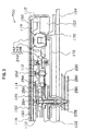
Fig. 1 is a plane view showing an outline shape viewing
a movement from a front side according to a first embodiment
of an analog electronic timepiece according to the invention
(in Fig. 1, portions of parts are omitted).
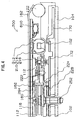
Fig. 2 is an outline partial sectional view showing a
portion from a second motor to a second hand according to the
first embodiment of the analog electronic timepiece according
to the invention.
Fig. 3 is an outline partial sectional view showing a
portion from a minute motor to a minute hand according to the
first embodiment of the analog electronic timepiece according
to the invention.
Fig. 4 is an outline partial sectional view showing a
portion from an hour motor to an hour hand according to the
first embodiment of the analog electronic timepiece according
to the invention.
Fig. 5 is a block diagram showing an outline constitution
of portions of circuits, motors, train wheels and indicators
according to the first embodiment of the analog electronic
timepiece of the invention.
Fig. 6 is a vertical sectional view showing an outline
shape of an attitude sensor applied to the analog electronic
timepiece according to the invention.
Fig. 7 is a plane view showing outline shapes of patterns
provided at an inner face of a case lower half portion of the
attitude sensor applied to the analog electronic timepiece of
the invention.
Fig. 8 is a vertical sectional view showing a state of
inclining the attitude sensor in the attitude sensor applied
to the analog electronic timepiece of the invention.
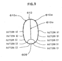
Fig. 9 is a vertical sectional view showing a state of
vertically arranging the attitude sensor in the attitude sensor
applied to the analog electronic timepiece of the invention.
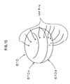
Fig. 10 is a perspective view showing shapes of lead wires
in the attitude sensor applied to the analog electronic timepiece
of the invention.
Fig. 11 is a table showing a relationship between attitudes
of arranging the analog electronic timepiece and conductive
states of patterns according to the first embodiment of the
analog electronic timepiece of the invention.
Fig. 12 is a flowchart showing operation of a constitution
of stopping all of motors (type 1A) based on a result of an
attitude detected by the attitude sensor according to the first
embodiment of the analog electronic timepiece of the invention.
Fig. 13 is a flowchart showing operation of a constitution
of stopping only a second motor (type 1B) based on a result
of the attitude detected by the attitude sensor according to
the first embodiment of the analog electronic timepiece of the
invention.
Fig. 14 is a flowchart showing operation of a constitution
of stopping a second motor and a minute motor (type 1C) based
on a result of the attitude detected by the attitude sensor
according to the first embodiment of the analog electronic
timepiece of the invention.
Fig. 15 is a plane view showing an outline shape viewing
a movement from a front side according to a second embodiment
of an analog electronic timepiece of the invention (in Fig.
15, portions of parts are omitted).
Fig. 16 is an outline partial sectional view showing a
portion from a second motor to a second hand according to the
second embodiment of the analog electronic timepiece of the
invention.
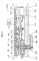
Fig. 17 is an outline partial sectional view showing a
portion from an hour/minute motor to a minute hand and an hour
hand according to the second embodiment of the analog electronic
timepiece of the invention.
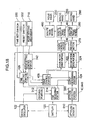
Fig. 18 is a block diagram showing an outline constitution
of portions of circuits, motors, train wheels and indicators
according to the second embodiment of the analog electronic
timepiece of the invention.
Fig. 19 is a flowchart showing operation of a constitution
of stopping all of motors (type 2A) based on a result of an
attitude detected by the attitude sensor according to the second
embodiment of the analog electronic timepiece of the invention.
Fig. 20 is a flowchart showing operation of a constitution
of stopping only a second motor (type 2B) based on a result
of the attitude detected by the attitude sensor according to
the second embodiment of the analog electronic timepiece of
the invention.
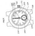
Fig. 21 is a plane view showing an outline shape of viewing
the analog electronic timepiece (having a second hand, having
a date wheel) according to the invention from a front side when
the analog electronic timepiece is completed (a state in which
a dial and hands are attached to a movement and contained in
a case), showing operation when the analog electronic timepiece
is set to "AUTO" mode.
Fig. 22 is a plane view showing an outline shape when
the movement is viewed from back side according to the first
embodiment of the analog electronic timepiece of the invention
(in Fig. 22, portions of parts are omitted).
Fig. 23 is an outline partial sectional view showing a
portion of a mode setting mechanism according to the first
embodiment of the analog electronic timepiece of the invention.
Fig. 24 is a flowchart showing operation of a constitution
(type 3A) for stopping all of motors based on a result of an
attitude detected by an attitude sensor according to a third
embodiment of an analog electronic timepiece of the invention.
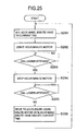
Fig. 25 is a flowchart showing operation of a constitution
(type 3B) for stopping an hour/minute motor based on a result
of an attitude detected by an attitude sensor according to the
third embodiment of the analog electronic timepiece of the
invention.
Fig. 26 is a plane view showing an outline shape of an
analog electronic timepiece (having no second hand, having no
date wheel) according to the invention from a front side thereof
when the analog electronic timepiece is completed (a state in
which a dial and hands are attached to a movement and contained
in a case), showing operation when the analog electronic
timepiece is set to "SLEEP" mode.
Fig. 27 is a plane view showing an outline shape of viewing
a movement from a front side according to a fourth embodiment
of an analog electronic timepiece of the invention (in Fig.
27, portions of parts are omitted).
Fig. 28 is an outline partial sectional view showing a
portion from a date motor to a date wheel according to the fourth
embodiment of the analog electronic timepiece of the invention.
Fig. 29 is a plane view showing an outline shape of viewing
a movement from back side according to the fourth embodiment
of the analog electronic timepiece of the invention (in Fig.
29, portions of parts are omitted).
Fig. 30 is a block diagram showing an outline constitution
of portions of circuits, motors, train wheels, and indicators
according to the fourth embodiment of the analog electronic
timepiece of the invention.
Fig. 31 is a flowchart showing operation of a constitution
(type 4A) for stopping all of motors based on a result of an
attitude detected by an attitude sensor according to the fourth
embodiment of the analog electronic timepiece of the invention.
Fig. 32 is a flowchart showing operation of a constitution
(type 4B) for stopping only a second motor based on a result
of an attitude detected by the attitude sensor according to
the fourth embodiment of the analog electronic timepiece of
the invention.
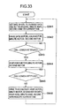
Fig. 33 is a flowchart showing operation of a constitution
(type 4C) for stopping an hour motor, a minute motor and a second
motor and not stopping a date motor based on a result of an
attitude detected by the attitude sensor according to the fourth
embodiment of the analog electronic timepiece of the invention.
[Best Mode for Carrying Out the Invention]
An explanation will be given of embodiments of an analog
electronic timepiece according to the invention in reference
to the drawings as follows.
(1) First embodiment of analog electronic timepiece
according to the invention
First, an explanation will be given of a first embodiment
of an analog electronic timepiece according to the invention.
(11) Constitution of movement of analog electronic
timepiece
(111) Structure of front side of movement
First, an explanation will be given of a structure of
a front side of a movement with respect to an analog electronic
timepiece according to the invention.
In reference to Fig. 1 through Fig. 5, according to a
first embodiment of an analog electronic timepiece of the
invention, amovement (machinebody) 700 of the analog electronic
timepiece is provided with a main plate 102 constituting a base
plate of the movement. A winding stem 110 is rotatably
integrated to a winding stem guide hole of the main plate 102.
A dial 104 (shown in Fig. 2 by imaginary lines) is attached
to the movement 700. The movement 700 is provided with a
changeover spring 166 (refer to Fig. 23) for determining a
position of the winding stem 110 in an axial line direction.
"Front side" of the movement 700 is arrangedwith a battery
120, a circuit block 116, an hour motor 210, an hour display
train wheel 220, a minute motor 240, a minute display train
wheel 250, a second motor 270, a second display train wheel
280 and so on. There is constructed a constitution in which
the hour display train wheel 220 is rotated by rotation of the
hour motor 210 and "hour" of current time is displayed by an
hour hand 230. There is constructed a constitution in which
the minute display train wheel 250 is rotated by rotation of
the minute motor 240 and "minute" of current time is displayed
by a minute hand 260. There is constructed a constitution in
which the second display train wheel 280 is rotated by rotation
of the second motor 270 and "second" of current time is displayed
by a second hand 290.
IC 740 and a crystal oscillator 122 are attached to the
circuit block 116. The circuit block 116 is fixed to the main
plate 102 and a train wheel bridge 112 by a switch spring 162
via an insulating plate 160. The changeover spring 166 is
integrally formed with the switch spring 162.
The battery 120 constitutes a power source of the analog
electronic timepiece. As the power source of the analog
electronic timepiece, a chargeable secondary battery can be
used and a chargeable condenser can be used. The crystal
oscillator 122 constitutes an oscillation source of the analog
electronic timepiece and is oscillated by, for example, 32,768
Hertz.
In reference to Fig. 1, Fig. 2 and Fig. 5, the second
motor 270 includes a second coil block 272, a second stator
274 and a second rotor 276. When the second coil block 272
inputs a second motor drive signal, the second stator 274 is
magnetized to thereby rotate the second rotor 276. The second
rotor 276 is constituted to rotate by, for example, 180 degrees
per second.
There is constructed a constitution in which based on
rotation of the second rotor 276, a second wheel 284 is rotated
via rotation of a second transmission wheel 282. The second
wheel 284 is constituted to rotate by one rotation per minute.
The second hand 290 is attached to the second wheel 284. The
second wheel 284 may be arranged at center of the analog
electronic timepiece or may be arranged at a position different
from the center of the analog electronic timepiece. The second
hand 290 constitutes a second display member. As the second
display member, the second hand may be used, a circular disk
may be used or a display member having other shape including
flower or a geometrical shape may be used.
The second display train wheel 220 includes the second
transmission wheel 282 and the second wheel 284. The second
rotor 276 and the second transmission wheel 282 are rotatably
supported by the main plate 102 and the train bridge 112. The
second wheel 284 is rotatably supported by a center pipe 126
provided at a second bridge 114 and the train bridge 112.
A date wheel 170 is rotatably supported by the main plate
102. Adatewheel holder 172 supports the date wheel 170 relative
to the main plate 102.
A battery minus terminal 170 is attached to the main plate
102. The battery minus terminal 170 conducts a cathode of the
battery 120 and a minus input portion Vss of IC 740 via a minus
pattern of the circuit block 116. A battery holder 172 is
attached to the switch spring 162. The battery holder 172 and
the switch spring 162 conduct an anode of the battery 120 and
a plus input portion Vdd of IC 740 via a plus pattern of the
circuit block 116.
In reference to Fig. 1, Fig. 3 and Fig. 5, the minute
motor 240 includes a minute coil block 242, a minute stator
244 and a minute rotor 246. When the minute coil block 242
inputs a minute motor drive signal, the minute stator 244 is
magnetized to thereby rotate the minute rotor 246. The minute
rotor 246 is constituted to rotate by, for example, 180 degrees
per 20 seconds.
There is constructed a constitution inwhich a first minute
transmission wheel 252 is rotated based on rotation of the minute
rotor 246 and a minute wheel 256 is rotated via a second minute
transmission wheel 254 based on rotation of the first minute
transmission wheel 252. The minute wheel 256 is constituted
to rotate by one rotation per hour. The minute hand 260 is
attached to the minute wheel 256. Rotational center of the
minute wheel 256 is the same as the rotational center of the
second wheel 284. The minute hand 260 constitutes a minute
display member. As the minute display member, the minute hand
may be used, a circular disk may be used, or a display member
having other shape including flower or a geometrical shape may
be used.
The minute display train wheel 250 includes the first
minute transmission wheel 252, the second minute transmission
wheel 254 and the minute wheel 256. The minute rotor 246,
the first minute transmission wheel 252 and the second minute
transmission wheel 254 are rotatably supported by the main plate
102 and the train bridge 112. The minute wheel 256 is brought
into contact with an outer peripheral portion of the center
pipe 126 provided at the second bridge 114 and is rotatably
supported thereby.
In reference to Fig. 1, Fig. 4, Fig. 5 and Fig. 22, the
hour motor 210 includes an hour coil block 212, an hour stator
214 and an hour rotor 216. When the hour coil block 212 inputs
an hour motor drive signal, the hour stator 214 is magnetized
to thereby rotate the hour rotor 126. The hour rotor 126 is
constituted to rotate by, for example, 180 degrees per 20
seconds.
A first transmission wheel 222 is rotated based on rotation
of the hour rotor 216. An hour wheel 226 is constituted to
rotate via rotation of a second hour transmission wheel 224
based on rotation of the first hour transmission wheel 222.
The hour wheel 216 is constituted to rotate by one rotation
per 12 hours. The hour hand 230 is attached to the hour wheel
226. Rotational center of the hour wheel 226 is the same as
rotational center of the minute wheel 256. Therefore, the
rotational center of the hour wheel 226, the rotational center
of the minute wheel 256 and the rotational center of the second
wheel 284 are the same.
The hour hand 230 constitutes an hour display member.
As the hour display member, the hour hand may be used, a circular
disk may be used, or a display member having other shape including
flower or a geometrical shape may be used.
The hour display train wheel 220 includes the first hour
transmission wheel 222, the second hour transmission wheel 224
and the hour wheel 226. The hour rotor 216, the first hour
transmission wheel 222 and the second hour transmission wheel
224 are rotatably supported by the main plate 102 and the train
bridge 112. The hour wheel 226 is brought into contact with
an outer peripheral portion of the hour wheel 256 and is rotatably
supported thereby.
Adate indicator drivingwheel 770 is constituted to rotate
by rotating the hour wheel 226. The date indicator driving
wheel 770 is provided to rotate by one rotation per day by rotation
of the hour wheel 226. A date indicator driving finger 772
provided at the date indicator driving wheel 770 is constituted
to feed the day wheel 170 by one tooth per day.
An attitude sensor 610 is attached to the circuit block
116 in a state of being contained in a casing. A material of
the casing may be a metal such as aluminum or may be plastic.
A method of attaching the casing to the circuit block 116 may
be by adhering, soldering or welding. Further, as a method
of attaching the casing to the circuit block 116, as shown by
Fig. 1 and Fig. 4, two attaching terminal portions provided
at the casing may fixedly be attached to the circuit block 116
by soldering, or the casing may directly be attached to the
circuit block 116.
Further, in reference to Fig. 1, the movement 700 of the
analog electronic timepiece according to the invention is
provided with a mode setting mechanism 710. The mode setting
mechanism 710 is provided for alternatively selecting
"automatic sleep mode", "forced sleep mode" and "normal hand
handling mode" as will be explained in details as follows.
Here, "automatic sleep mode" indicates a mode capable
of detecting an attitude of an analog electronic timepiece and
controlling to drive motors based on a result of the detection.
Further, "forced sleep mode" indicates a mode of stopping
operation of hands of an analog electronic timepiece without
detecting an attitude of the analog electronic timepiece.
Further, "normal hand handling mode" indicates a mode of
displaying time always by all of hands without detecting an
attitude of an analog electronic timepiece and without stopping
operation of hands (for example, hour hand, minute hand, second
hand) of an analog electronic timepiece.
(112) Structure of back side of movement
Next, an explanation will be given of a structure of a
back side of the movement 700 of the analog electronic timepiece
according to the invention.
In reference to Fig. 1, Fig. 22 and Fig. 23, a clutch
wheel 714 is integrated to the winding stem 110 to rotate by
rotation of the winding stem 110. That is, a square hole formed
in the clutch wheel 714 is fitted to a square shaft of the winding
stem 110. A mode display intermediate wheel 720 in a ring-like
shape is integrated to the main plate 102 to rotate by rotation
of the clutch wheel 714. A mode display wheel 722 is integrated
to the main plate 102 to rotate by rotation of the mode display
intermediate wheel 720.
A mode position determining spring 726 is provided for
determining a position of the mode display wheel 722 in the
rotational direction. For example, the position of the mode
display wheel 722 in the rotational direction can be determined
by bringing a regulating portion formed at a front end of the
mode positioning spring 726 into contact with one of a plurality
of positioning groove portions provided at the mode display
wheel 722. According to the movement 700 of the analog
electronic timepiece of the invention, there is constructed
a constitution in which by the mode positioning spring 726,
the mode display wheel 722 is positioned at positions of 6
portions at every 60 degrees.
A mode display plate 728 is fixed to the mode display
wheel 722. A portion of the mode display plate 728 or a mode
display face 730 is disposed in a window portion 104b of the
dial 104. Characters and/or symbols for displaying modes are
provided at the mode display face 730.
In reference to Fig. 21, characters for displaying 3 kinds
of modes, "AUTO", "SLEEP" and "NORM" are printed on the mode
display face 730 of the mode display plate 728. The characters
for displaying the modes, "AUTO", "SLEEP" and "NORM" are printed
at positions of 6 portions of the mode display face 730 to repeat
twice in the order of "AUTO", "SLEEP" and "NORM". According
to the constitution, a user can read a set mode by characters
displayed at a position in correspondence with the window portion
104b of the dial 104.
According to the movement 700 of the analog electronic
timepiece of the invention, there is indicated by "AUTO",
"automatic sleep mode", that is, a mode capable of detecting
the attitude of the analog electronic timepiece and controlling
to drive motors based on a result of the detection. Further,
there is indicated by "SLEEP", "forced sleep mode", that is,
a mode of stopping operation of hands of the analog electronic
timepiece without detecting the attitude of the analog
electronic timepiece, or regardless of the detected attitude.
Further, there is indicated by "NORM", "normal hand handling
mode", that is, a mode of displaying time always by all of hands
without detecting the attitude of the analog electronic
timepiece, or regardless of the detected attitude and without
stopping operation of hands (for example, hour hand, minute
hand, second hand) of the analog electronic timepiece.
As a modified example, there can be constructed a
constitution in which characters for displaying three kinds
of modes, "AUTO", "SLEEP" and "NORM" are printed on the dial
104, there is provided a mode indicating mark or a mode indicating
needle for indicating modes at the mode display wheel 722 and
modes are indicated by corresponding the characters for
displaying the modes to the mode indicating mark or the mode
indicating needle.
Two modes can be constituted to set, three modes as
illustrated can be constituted to set, or four or more of modes
can be constituted to set by selecting the structure of the
mode positioning spring 726 and the structure of the mode display
wheel 722.
A mode setting spring 730 is attached to the mode display
wheel 722 to rotate by rotation of the mode display wheel 722.
By rotating the mode display wheel 722, the mode setting spring
730 is positioned at positions of 6 portions at every 60 degrees.
In correspondence with the positions of 6 portions for
positioning the mode setting spring 730, 3 kinds of mode setting
patterns are provided in the circuit block 116.
There is constructed a constitution in which in
correspondence with positioning the mode setting spring 730
at the positions of 6 portions, 3 kinds of mode setting signals
are inputted to IC 740 via 3 kinds of the mode setting patterns.
Therefore, the mode setting mechanism 710 includes the
clutch wheel 714, the mode display wheel 722, the mode display
wheel 724, the mode positioning spring 726 and the mode setting
patterns.
The date wheel 170 is supported by the date wheel holder
172 to be rotatable relative to the main plate 102. The date
wheel 170 is constituted to feed by one tooth per day by rotating
the date wheel finger 772 provided at the date driving wheel
770.
(12) Constitution of IC
Next, an explanation will be given of a constitution of
IC according to the first embodiment of the analog electronic
timepiece of the invention.
In reference to Fig. 5, IC 740 includes a dividing portion
312, a time measuring portion 314 and a time setting portion
316. The dividing portion 312 is constituted to divide a signal
outputted by the crystal oscillator 122. The time measuring
portion 314 is constituted to measure current time based on
an output signal of the dividing portion 312. The time setting
portion 316 is constituted to output signals for controlling
to drive the motors.
A drive control portion 328 is provided to control
operation of an hour motor drive portion 320, a minute motor
drive portion 322 and a second motor drive portion 324.
A time set switch 330 is provided for controlling operation
of the time setting portion 316. There is constructed a
constitution in which by operating the time set switch 330,
the time setting portion 316 is operated, the drive control
portion 328 is operated and the hour motor driving portion 320,
the minute motor driving portion 322 and the second motor driving
portion 324 can be operated.
The time set switch 330 is constituted by a switch terminal
portion integrally formed with the switch spring 162 and a switch
pattern of the circuit block 116.
A reset switch 332 is provided to reset operation of the
time setting portion 316. There is constructed a constitution
in which by operating the reset switch 332, the time setting
portion 316 is reset and by operating the drive control portion
328, operation of the hour motor driving portion 320, the minute
motor driving portion 322 and the second motor driving portion
324 can be stopped.
The reset switch 332 is constituted to operate by pulling
out the winding stem 110.
There is provided a mode setting control portion 742 for
storing a set mode and outputting a signal with regard to the
set mode based on operation of the mode setting mechanism 710.
An attitude detecting portion 340 is provided to detect
an attitude of the analog electronic timepiece based on an output
signal of the attitude sensor 610.
An output determining portion 344 is constituted to
operate the drive control portion 328 by inputting an output
signal of the time measuring portion 314 based on an output
signal of the attitude detecting portion 340.
The hour motor driving portion 320.is constituted to be
capable of outputting a signal for driving the hour motor 210
to the hour motor 210 and stopping to drive the hour motor 210
based on the output signal of the drive control portion 328.
By driving the hour motor 210, the hour display train wheel
220 is rotated and "hour" can be displayed by the hour hand
230.
The minute motor driving portion 322 is constituted to
be capable of outputting a signal for driving the minute motor
240 to the minute motor 240 based on the output signal of the
drive control portion 328 and stopping to drive the minute motor
240 based on the output signal of the drive control portion
328. By driving the minute motor 240, the minute display train
wheel 250 is rotated and "minute" can be displayed by the minute
hand 260.
The second motor driving portion 324 is constituted to
be capable of outputting a signal for driving the second motor
270 to the second motor 270 based on the output signal of the
drive control portion 328 and stopping to drive the second motor
270 based on the output signal of the drive control portion
328. By driving the second motor 270, the second display train
wheel 280 is rotated and "second" can be displayed by the second
hand 290.
When the mode setting mechanism 710 is operated to set
"automatic sleep mode", the mode setting control portion 742
outputs a signal with regard to "automatic sleep mode" to the
drive control portion 328 and the attitude detecting portion
340. Therefore, when the attitude detecting portion 340 is
set to "automatic sleep mode", the attitude detecting portion
340 is constituted to carry out operation of detecting the
attitude to the analog electronic timepiece based on the output
signal of the attitude sensor 610.
When the mode detecting mechanism 710 is operated to set
to "forced sleep mode", the mode setting control portion 742
outputs a signal with regard to "forced sleep mode" to the drive
control portion 328 and the attitude detecting portion 340.
Therefore, when the attitude detecting portion 340 is set to
"forced sleep mode", the attitude detecting portion 340 is
constituted not to carry out operation of detecting the attitude
of the analog electronic timepiece. Further, there is
constructed a constitution in which when the mode setting
mechanism 710 is set to "forced sleep mode", it is possible
that based on the output signal of the drive control portion
328, the hour motor drive portion 320 stops driving the hour
motor 210, the minute motor drive portion 322 stops driving
the minute motor 240 and the second motor drive portion 324
stops driving the second motor 270.
As a modified example, there can also be constructed a
constitution in which when the mode setting mechanism 710 is
set to "forced sleep mode", even when the attitude detecting
portion 340 detects the attitude of the analog electronic
timepiece, regardless of a result of the detection, the hour
motor drive portion 320 stops driving the hour motor 210, the
minute motor drive portion 322 stops driving the minute motor
240 and the second motor drive portion 324 stops driving the
second motor 270.
Further, as a modified example, the drive control portion
328 may be constituted such that when the mode setting mechanism
710 is set to "forced sleep mode", after stopping to operate
the hour motor 210, the minute motor 240 and the second motor
270, when a predetermined time period has elapsed, the hour
motor 210, the minute motor 240 and the second motor 270 are
operated for a constant period of time and the hour motor 210,
the minute motor 240 and the second motor 270 are stopped again.
By constituting in this way, oil used in the hour display train
wheel 220, the minute display train wheel 250 and the second
display train wheel 280 can effectively prevented from being
solidified. That is, by the constitution, so-to-speak
"maintenance drive" of train wheels can periodically be carried
out.
It is preferable that the predetermined time period after
stopping the hour motor 210, the minute motor 240 and the second
motor 270, is set to, for example, a time interval of 7 days
through 60 days.
It is preferable that the constant period of time for
operating the hour motor 210, the minute motor 240 and the second
motor 270 is a time period for respectively rotating the hour
hand 230, the minute hand 260 and the second hand 290 by one
rotation.
There is constructed a constitution in which when the
mode setting mechanism 710 is operated and set to "normal hand
handling mode", the attitude detecting portion 340 does not
carry out the operation of detecting the attitude of the analog
electronic timepiece and carry out normal hand handling such
that based on the output signal of the drive control portion
328, the hour motor drive portion 320 drives the hour motor
210, the minute motor drive portion 322 drives the minute motor
240, the second motor drive portion 324 drives the second motor
270, "hour" is displayed by the hour hand 230, "minute " is
displayed by the minute hand 260 and "second" is displayed by
the second hand 290.
As a modified example, there can also be constructed a
constitution in which when the mode setting mechanism 710 is
set to "normal hand handling mode", even when the attitude
detecting portion 340 detects the attitude of the analog
electronic timepiece, regardless of a result of the detection,
there is carried out normal hand handling such that the hour
motor drive portion 320 drives the hour motor 210, the minute
motor drive portion 322 drives the minute motor 240, the second
motor drive portion 324 drives the second motor 270, "hour"
is displayed by the hour hand 230, "minute" is displayed by
the minute hand 260 and "second" is displayed by the second
hand 290.
According to the embodiment of the analog electronic
timepiece of the invention, circuits for executing various
functions may be constituted in IC, for example, CPU, ROM, RAM
and the like are provided in IC. IC may be PLA IC including
programs for executing various operations.
Further, according to the embodiment of the analog
electronic timepiece of the invention, as necessary, along with
IC, externally mounted elements such as resistors, condensers,
coils, diodes or transistors can be used.
(13) Attitude sensor
Next, an explanation will be given of an attitude sensor
applied to the analog electronic timepiece of the invention.
Further, the attitude sensor applied to the analog
electronic timepiece of the invention is not limited to a
constitution described below but any publicly-known attitude
sensor can be used.
In reference to Fig. 6, the attitude sensor 610 is provided
with a case 610a having a shape viewed from above being
substantially circular and a shape viewed from a side being
substantially "oval".
The "oval shape" defined here includes a shape in which
a portion of a circular arc having a radius of a first dimension
and a portion of a circular arc having a radius the same as
the radius of the first dimension, are arranged to be opposed
to each other such that inner sides thereof are proximate to
each other and portions of the both circular arcs are connected
by a portion of a circular arc having a radius of a second dimension,
includes a shape in which portions of the both circular arcs
are connected by a straight line and includes a shape in which
portions of the both circular arcs are connected by portions
of a plurality of circular arcs. In this case, the first
dimension is preferably smaller than the second dimension.
The case 610a is formed symmetrically in the up and down
direction relative to a central plane 610c. That is, the case
610a includes a case upper half portion 610u and a case lower
half portion 610d. Therefore, according to the case 610a, the
case upper half portion 610u and the case lower half portion
610d are formed symmetrically relative to the central plane
610c. That is, the case upper half portion 610u and the case
lower half portion 610d are formed by the same dimensions and
shape.
Therefore, for example, the case 610a can be formed by
fabricating two of the case upper half portions 610u and bonding
together the two case upper half portions 610u at portions
thereof in correspondence with the plane 610c. The bonding
may be carried out by adhesion, may be carried out by welding
or may be carried out by using an adhering tape.
In this way, by forming the case 610 having the shape
viewed from side substantially in the oval shape, the small-sized
and thin attitude sensor 610 can be realized.
In Fig. 6, there are defined an X axis line (in Fig. 6,
right direction is defined as positive direction) and a Y axis
line (in Fig. 6, a direction orthogonal to paper face and directed
from top to back of paper face is defined as positive direction)
in the horizontal direction and there is defined a Z axis line
(in Fig. 6, upper direction is defined as positive direction)
in a direction orthogonal to the X axis line and the Y axis
line.
According to the case 610a, a shape of a plane including
the X axis line and the Y axis line, that is, a shape of a
cross-sectional face of the central portion, is substantially
circular and a shape in a plane including the X axis line and
the Z axis line, that is, a shape of a vertical face at the
central portion is substantially oval.
The case 610a is formed by a board of plastic such as
polyimide or glass epoxy or an insulating material such as
quartz.
In reference to Fig. 6 and Fig. 7, a pattern constituting
an electrode of the attitude sensor 610 (hereinafter, simply
referred to as "pattern") A1 is provided at an inner face of
a center of the case lower half portion 610d. An outer peripheral
portion of pattern A1 is formed in a circular shape.
Pattern B1 is provided at the inner face of the center
of the case lower half portion 610d and on an outer peripheral
side of pattern A1. An inner peripheral portion of pattern
B1 is formed in a circular shape concentric with the outer
peripheral portion of pattern A1 spaced apart from the outer
peripheral portion of pattern A1 at an interval. An outer
peripheral portion of pattern B1 is formed in a circular shape
concentric with the inner peripheral portion of B1 spaced apart
from the inner peripheral portion of pattern B1 at an interval.
That is, pattern B1 is formed in a ring-like shape.
Pattern C1 is provided at the inner face of the center
of the case lower half portion 610d and on an outer peripheral
side of pattern B1. An inner peripheral portion of pattern
C1 is formed in a circular shape concentric with the outer
peripheral portion of pattern B1 spaced apart from the outer
peripheral portion of pattern B1 at an interval. An outer
peripheral portion of pattern C1 is formed in a circular shape
concentric with the inner peripheral portion of pattern C1 spaced
apart from the inner peripheral portion of pattern C1 at an
interval. That is, pattern C1 is formed in a ring like shape.
Pattern D1 is provided at the inner face of the center
of the case lower half portion 610d and on an outer peripheral
side of pattern C1. An inner peripheral portion of pattern
D1 is formed in a circular shape concentric with the outer
peripheral portion of pattern C1 spaced apart from the outer
peripheral portion pattern C1 at an interval. An outer
peripheral portion of pattern D1 is formed in a circular shape
concentric with the inner peripheral portion of pattern D1 spaced
apart from the inner peripheral portion of pattern D1 at an
interval. That is, pattern D1 is formed in a ring like shape.
Pattern E1 is provided at the inner face of the center
of the case lower half portion 610d and on an outer peripheral
side of pattern D1. An inner peripheral portion of pattern
E1 is formed in a circular shape concentric with the outer
peripheral portion of pattern D1 spaced apart from the outer
peripheral portion of pattern D1 at an interval. An outer
peripheral portion of pattern E1 is formed in a circular shape
concentric with the inner peripheral portion of pattern E1 spaced
apart from the inner peripheral portion of pattern E1 at an
interval. That is, pattern E1 is formed in a ring like shape.
There are formed patterns A2, B2, C2, D2 and E2 at the
case upper half portion 610u similar to the shapes of the patterns
A1, B1, C1, D1 and E1. That is, an outer peripheral portion
of pattern A2 is formed in a circular shape and patterns B2,
C2, D2 and E2 are formed in a ring-like shape. Further, shapes
of patterns A1, B1, C1, D1 and E1 of the case lower half portion
610d and shapes of patterns A2, B2, C2, D2 and E2 of the case
upper half portion 610u are substantially the same respectively.
As has been explained, the respective patterns A1, B1,
C1, D1, E1, A2, B2, C2, D2 and E2 are insulated from each other.
According to the embodiment of the analog electronic
timepiece of the invention, the attitude sensor 610 is arranged
relative to the main plate 102 such that the X-axis line and
the Y-axis line are in parallel with a surface of the main plate
102 and in parallel with a surface of the dial 104. Therefore,
the attitude sensor 610 is constituted relative to the main
plate 102 such that the Z axis line is orthogonal to the surface
of the main plate 102 and orthogonal to the surface of the dial
104.
In reference to Fig. 10, lead wires for transmitting
signals from the patterns are respectively connected to patterns
A1, B1, C1, D1, E1, A2, B2, C2, D2 and E2.
Detecting patterns A1, B1, C1, D1, E1, A2, B2, C2, D2
and E2 are provided at the circuit block 116. Patterns A1,
B1, C1, D1, E1, A2, B2, C2, D2 and E2 are connected to the detecting
patterns A1, B1, C1, D1, E1, A2, B2, C2, D2 and E2 of the circuit
block 116 by the lead wires. The detecting patterns A1, B1,
C1, D1, E1 A2, B2, C2, D2 and E2 of the circuit block 116 are
respectively connected to detecting pattern input terminals
of IC 118. A detected signal inputted to the detecting pattern
input terminal of IC 118 is inputted to the attitude detecting
portion 340.
Therefore, by detecting conductive states of the
detecting patterns A1, B1, C1, D1 E1, A2, B2, C2, D2 and E2
of the circuit block 116, conductive states of patterns A1,
B1, C1, D1, E1, A2, B2, C2, D2 and E2 of the attitude sensor
610 can be detected.
In reference to Fig. 6, a conductive fluid 608 is contained
in the case 610a. The conductive fluid 608 is, for example,
mercury. Although the volume of the conductive fluid 608 is
1/28 of the volume of the case 610a in the example shown by
Fig. 6, it is preferable that the volume of the conductive fluid
608 is 1/50 through 1/10 of the volume of the case 610a. The
volume of the conductive fluid 608 is determined to be capable
of being brought into contact with two patterns or three
patterns.
In the horizontal state shown by Fig. 6, the conductive
fluid 608 is brought into contact with pattern A1 and pattern
B1. Therefore, in the state shown by Fig. 6, pattern A1 and
pattern B1 are shortcircuited (that is, conducted to each other)
by the conductive fluid 608.
That is, Fig. 6 shows a state of the attitude sensor 610
when the analog electronic timepiece of the invention is arranged
in "flat attitude". When pattern A1 and pattern B1 are conducted
to each other, the attitude detecting portion 340 outputs a
detected signal when "flat attitude" is detected. In this case,
"flat attitude" is attitude of "dial lower".
Next, in reference to Fig. 8, in a state in which the
attitude sensor 610 is arranged to be inclined by 45 degrees
relative to a horizontal face, the conductive fluid 608 is
brought into contact with pattern C1, pattern D1 and pattern
E1. Therefore, in the state shown by Fig. 8, pattern C1, pattern
D1 and pattern E1 are shortcircuited (that is, conducted to
each other) by the conductive fluid 608.
That is, Fig. 8 shows a state of the attitude sensor 610
when the analog electronic timepiece of the invention is arranged
in "skewed attitude". When pattern C1, pattern D1 and pattern
E1 are conducted to each other, the attitude detecting portion
340 outputs a detected signal when "skewed attitude" is detected.
Next, in reference to Fig. 9, in a state in which the
attitude sensor 610 is arranged to make 90 degrees relative
to the horizontal face (vertically), the conductive fluid 608
is brought into contact with pattern E1 and pattern E2.
Therefore, in the state shown by Fig. 9, pattern E1 and pattern
E2 are shortcircuited (that is, conducted to each other) by
the conductive fluid 608.
That is, Fig. 9 shows a state of the attitude sensor 610
when the analog electronic timepiece of the invention is arranged
in "erect attitude". When pattern E1 and pattern E2 are
conducted to each other, the attitude detecting portion 340
outputs a detected signal when "erect attitude" is detected.
In reference to Fig. 11, there is shown relationships
between states of conducting various patterns and the states
of respective attitudes in the attitude sensor applied to the
analog electronic timepiece of the invention.
In Fig. 11, notations A1, B1, C1, D1, E1 E2, D2, C2,
B2 and A2 respectively designate pattern A1, pattern B1 pattern
C1, pattern D1, pattern E1, pattern E2, pattern D2, pattern
C2, pattern B2 and pattern A2. Notation "ON" designates that
a corresponding pattern is brought into a state of being
conducted to other pattern designated as "ON". "OFF"
designates that a corresponding pattern is brought into a state
in which the pattern is not conducted to any other pattern.
(131) Attitude state 1
Attitude state 1 shown in Fig. 11 corresponds to a case
in which the analog electronic timepiece of the invention is
brought into "flat attitude". Here, "flat attitude" is an
attitude of "dial lower".
Attitude state 1 corresponds to a case in which the analog
electronic timepiece of the invention falls in a range of 0
degree through 7 degree relative to the horizontal face.
According to attitude state 1, in the circuit block 116,
pattern A1 and pattern B1 are constituted to conduct each other.
(132) Attitude state 2
Attitude state 2 shown in Fig. 11 corresponds to a case
in which the analog electronic timepiece of the invention is
brought into "flat attitude".
Attitude state 2 corresponds to a case in which the analog
electronic timepiece of the invention falls in a range of 8
degree through 12 degree relative to the horizontal face.
According to attitude state 2, in the circuit block 116,
pattern B1 and pattern C1 are constituted to conduct each other.
(133) Attitude state 3
Attitude state 3 shown in Fig. 11 corresponds to a case
in which the analog electronic timepiece of the invention is
brought into "flat attitude".
Attitude state 3 corresponds to a case in which the analog
electronic timepiece of the invention falls in a range of 13
degree through 30 degree relative to the horizontal face.
According to attitude state 3, in the circuit block 116,
pattern B1, pattern C1 and pattern D1 are constituted to conduct
each other.
(134) Attitude state 4
Attitude state 1 shown in Fig. 11 corresponds to a case
in which the analog electronic timepiece of the invention is
brought into "skewed attitude".
Attitude state 4 corresponds to a case in which the analog
electronic timepiece of the invention falls in a range of 31
degree through 60 degree relative to the horizontal face.
According to attitude state 4, in the circuit block 116,
pattern C1, pattern D1 and E1 are constituted to conduct each
other.
(135) Attitude state 5
Attitude state 5 shown in Fig. 11 corresponds to a case
in which the analog electronic timepiece of the invention is
brought into "erect attitude".
Attitude state 5 corresponds to a case in which the analog
electronic timepiece of the invention falls in a range of 61
degree through 89 degree relative to the horizontal face.
According to attitude state 5, in the circuit block 116,
pattern D1, pattern E1 and pattern E2 are constituted to conduct
each other.
(136) Attitude state 6
Attitude state 6 shown in Fig. 11 corresponds to a case
in which the analog electronic timepiece of the invention is
brought into "erect attitude".
Attitude state 6 corresponds to a state in which the analog
electronic timepiece of the invention is at 90 degree relative
to the horizontal face, that is, arranged vertically.
According to attitude state 6, in the circuit block 606,
pattern E1 and pattern E2 are constituted to conduct each other.
(137) Attitude state 7
Attitude state 7 shown in Fig. 11 corresponds to a case
in which the analog electronic timepiece of the invention is
brought into "erect attitude".
Attitude state 7 corresponds to a case in which the analog
electronic timepiece of the invention falls in a range of 91
degree through 119 degree relative to the horizontal face.
According to attitude state 7, in the circuit block 116,
pattern E1, pattern E2 and D2 are constituted to conduct each
other.
(138) Attitude state 8
Attitude state 8 shown in Fig. 11 corresponds to a case
in which the analog electronic timepiece of the invention is
brought into "skewed attitude".
Attitude state 8 corresponds to a case in which the analog
electronic timepiece of the invention falls in a range of 120
degree through 149 degree relative to the horizontal face.
According to attitude state 8, in the circuit block 116,
pattern E2, pattern D2 and pattern C2 are constituted to conduct
each other.
(139) Attitude state 9
Attitude state 9 shown in Fig. 11 corresponds to a case
in which the analog electronic timepiece of the invention is
brought into "back flat attitude". Here, "back flat attitude"
is an attitude of "dial upper".
Attitude state 9 corresponds to a case in which the analog
electronic timepiece of the invention falls in a range of 150
degree through 167 degree relative to the horizontal face.
According to attitude state 9, in the circuit block 116,
pattern D2, pattern C2 and pattern B2 are constituted to conduct
each other.
(1310) Attitude state 10
Attitude state 10 shown in Fig. 11 corresponds to a case
in which the analog electronic timepiece of the invention is
brought into "back flat attitude". Here, "back flat attitude"
is an attitude of "dial upper".
Attitude state 10 corresponds to a case in which the analog
electronic timepiece of the invention falls in a range of 168
degree through 172 degree relative to the horizontal face.
According to attitude state 10, in the circuit block 116,
pattern C2 and pattern B2 are constituted to conduct each other.
(1311) Attitude state 11
Attitude state 11 shown in Fig. 11 corresponds to a case
in which the analog electronic timepiece of the invention is
brought into "back flat attitude". Here, "back flat attitude"
is an attitude of "dial upper".
Attitude state 11 corresponds to a case in which the analog
electronic timepiece of the invention falls in a range of 173
degree through 180 degree relative to the horizontal face.
According to attitude state 11, in the circuit block 116,
pattern B2 and pattern A2 are constituted to conduct each other.
(14) Operation of analog electronic timepiece of the
invention
Next, an explanation will be given of operation of the
analog electronic timepiece of the invention.
(141) Type 1A
An explanation will be given of a constitution (type 1A)
for stopping all the motors based on a result of an attitude
detected by the attitude sensor when the analog electronic
timepiece of the invention is set to "automatic SLEEP mode",
according to the first embodiment of the analog electronic
timepiece of the invention.
In reference to Fig. 5 and Fig. 12, first, the analog
electronic timepiece is reset by operating the reset switch
332, by operating the time set switch 330, the hour motor 210
is operated and the hour hand 230 is set to "hour" of current
time, the minute motor 240 is operated and the minute hand 260
is set to "minute" of current time and the second motor 270
is operated and the second hand 290 is set to "second" (step
S121).
Next, the reset switch 332 is released, the hour motor
210 is operated, "hour" of current time is displayed by the
hour hand 230, the minute motor 240 is operated, "minute" of
current time is displayed by the minute hand 260, the second
motor 270 is operated and "second" of current time is displayed
by the second hand 290 (step S122).
When a signal indicating the dial lower " attitude (flat
attitude) outputted by the attitude sensor 610 is continuously
outputted for a threshold of a constant detecting time period,
for example, 1 minute, the attitude detecting portion 340
determines that the analog electronic timepiece is brought into
the dial lower attitude (flat attitude) and when the signal
indicating the dial lower attitude (flat attitude) outputted
by the attitude sensor 610 is not outputted continuously for
a threshold of a constant detecting time period, for example,
1 minute, the attitude detecting portion 340 determines that
the analog electronic timepiece is not brought into the dial
lower attitude (flat attitude) (step S123).
The threshold is set preferably in a range of 0.5 through
60 minutes and is set more preferably in a range of 1 through
5 minutes.
By constituting in this way, the attitude of the analog
electronic timepiece can be detected firmly by excluding
influence by chattering of the attitude sensor 610.
Or, the determination by the attitude detecting portion
340 that the analog electronic timepiece is brought into the
dial lower attitude (flat attitude) can be carried out by
detecting that the signal outputted by the attitude sensor 610
is outputted by a plurality of times during a constant time
period. For example, there can be constructed a constitution
in which in one time operation of the attitude detecting portion
340 for detecting the attitude of the analog electronic timepiece,
when the signal determining that the analog electronic timepiece
is brought into the dial lower attitude (flat attitude) is
similarly outputted at two times of immediately after starting
of detection and one minute after starting of detection, the
analog electronic timepiece is determined to be brought into
the dial lower attitude (flat attitude) by the attitude detecting
portion 340.
It is preferable in the constitution that the signal
outputted by the attitude sensor 610 is outputted by a
predetermined number of times during a constant time period.
It is preferable that the predetermined number of times is set
in, for example, a range of 2 through 10 times.
A time interval of operation for detecting the attitude
of the analog electronic timepiece by the attitude detecting
portion 340 is constituted such that, for example, when the
above-described threshold is set in a range of 1 through 5 minutes,
operation is carried out once per 10 minutes. It is preferable
that the time interval is set in a range of 5 through 60 minutes.
By constituting in this way, the attitude of the analog
electronic timepiece can be detected firmly at every constant
time period.
When the attitude detecting portion 340 determines that
the analog electronic timepiece is brought into the dial lower
attitude (flat attitude), the output determining portion 340
outputs a signal for stopping to drive the motors to the drive
control portion 328. When the drive control portion 328 inputs
the signal outputted by the output determining portion 344,
the drive control portion 328 stops driving the hour motor 210
by the hour motor drive portion 320, stops driving the minute
motor 240 by the minute motor drive portion 322 and stops driving.
the second motor 270 by the second motor drive portion 324 (step
S124).
As a result, the hour motor 210 stops operating, the hour
hand 230 is stopped at a position indicated thereby, the minute
motor 240 stops operating, the minute hand 260 is stopped at
a position indicated thereby, the second motor 270 stops
operating and the second hand 290 is stopped at a position
indicated thereby.
The output determining portion 344 inputs a signal with
regard to current time outputted by the time measuring portion
314 and measures a difference between current time and time
at which the hour hand 230, the minute hand 260 and the second
hand 290 are stopped.
When the attitude detecting portion 340 determines that
the analog electronic timepiece is not brought into the dial
lower attitude (flat attitude), after elapse of a constant time
interval, operation at step S123 is carried out again.
After the hour motor 210 stops operating, the minute motor
240 stops operating and the second motor 270 stops operating,
the attitude detecting portion 340 determines whether the signal
indicating the dial lower attitude "flat attitude" outputted
by the attitude sensor 610 is outputted (step S125).
When the attitude detecting portion 340 determines that
the analog electronic timepiece is not brought into the dial
lower attitude (flat attitude), the output determining portion
344 outputs a signal for driving to accelerate the motors to
the drive control portion 328. When the drive control portion
328 inputs the signal outputted by the output determining portion
344, the drive control portion 328 operates the hour motor drive
portion 320 to thereby drive to accelerate the hour motor 210
to reach a position at which the hour hand 230 indicates current
time, operates the minute motor drive portion 322 to thereby
drive to accelerate the minute motor 240 to reach a position
at which the minute hand 260 indicates current time and operates
the second motor drive portion 324 to thereby drive to accelerate
the second motor 270 to reach a position at which the second
hand 290 indicates current time (step S126).
At S126, when the signal outputted by the attitude sensor
610 for indicating that the analog electronic timepiece is not
brought into the dial lower attitude (flat attitude), is
outputted continuously for a threshold of a constant detecting
time period, for example, 0.1 second, the attitude detecting
portion 340 determines that the analog electronic timepiece
is not brought into the dial lower attitude (flat attitude).
The threshold is set preferably in a range of 0.1 through
0.5 second and is set more preferably in a range of 0.1 through
0.2 second.
Or, the determination by the attitude detecting portion
340 that the analog electronic timepiece is not brought into
the dial lower attitude (flat attitude), is carried out by
detecting that the signal outputted by the attitude sensor 610
is outputted continuously during a constant time period. For
example, there can also be constructed a constitution in which
in one time operation of the attitude detecting portion 340
for detecting the attitude of the analog electronic timepiece,
when there is outputted the signal for determining that the
analog electronic timepiece is brought into the dial lower
attitude (flat attitude) continuously at two times during a
time period of 0.1 second, the analog electronic timepiece is
determined to be brought into the dial lower attitude (flat
attitude) by the attitude detecting portion 340.
As a result, the hour hand 230 indicates "hour" of current
time, the minute hand 260 indicates "minute" of current time
and the second 290 indicates "second" of current time.
According to the accelerated driving method, all of the
hour hand 230, the minute hand 260 and the second hand 290 may
be rotated regularly in the clockwise direction or all of the
hour hand 230, the minute hand 260 and the second hand 290 may
be rotated reversely in the counterclockwise direction. Or,
according to the accelerated driving method, there may be
constructed a constitution in which there is calculated a
relationship between a position which the hour hand 230 intends
to indicate and a position at which the hour hand 230 is stopped,
there is calculated a relationship between a position in which
the minute hand 260 intends to indicate and a position at which
the minute hand 260 is stopped, there is calculated a
relationship between a position which the second hand 290 intends
to indicate and a position at which the second hand 290 is stopped
and the hour hand 230, the minute hand 260 and the second hand
290 are respectively rotated in a rotating direction in regular
rotation or reverse rotation in which the hour hand 230, the
minute hand 260 and the second hand 290 can reach the positions
indicated thereby more fast.
For example, the output determining portion 344 is
constituted to be provided with a counter for measuring a time
period between time of stopping the hour hand 230, the minute
hand 260 and the second hand 290 and current time. Further,
the counter is constituted to start when the hour hand 230,
the minute hand 260 and the second hand 290 are stopped and
the counter is constituted to stop when the attitude detecting
portion 340 determines that the analog electronic timepiece
is not brought into the dial lower attitude (flat attitude).
Further, by operating the drive control portion 328, the hour
motor 210 is driven to accelerate to reach the position at which
the hour hand 230 indicates current time by operating the hour
motor drive portion 320, the minute motor 240 is driven to
accelerate to reach the position at which the minute hand 260
indicates current time by operating the minute motor drive
portion 322 and the second motor 270 is driven to accelerate
to reach the position at which the second hand 290 indicates
current time by operating the second motor drive portion 324.
In this case, there may be constructed a constitution
in which with regard to the time period for driving to accelerate
the hands in this way, the hands may further be driven to
accelerate for correction by using the counter. By the
constitution, current time can accurately be displayed by the
hour hand 230, the minute hand 260 and the second hand 290.
Or, the output determining portion 344 is constituted
to be provided with a calculating portion for calculating
relationships between positions at which the hour hand 230,
the minute hand 260 and the second hand 290 are stopped and
positions to be indicted by the hour hand 230, the minute hand
260 and the second hand 290 at current time. Further, there
can also be constructed a constitution in which by operating
the drive control portion 328, the hour motor 210 is driven
to accelerate to reach the position at which the hour hand 230
indicates current time by operating the hour motor drive portion
320, the minute motor 240 is driven to accelerate to reach the
position at which the minute hand 260 indicates current time
by operating the minute motor drive portion 322 and the second
motor 270 is driven to accelerate to reach the position at which
the second hand 290 indicates current time by operating the
second motor drive portion 324.
When current time is displayed by the hour hand 230, the
minute hand 260 and the second hand 290 by driving to accelerate
the hour hand 230, the minute hand 260 and the second hand 290,
the operation returns to step 122 and normal operation is carried
out.
Further, according to the constitution in which the hour
motor 210 is driven to accelerate to reach the position at which
the hour hand 230 indicates current time by the hour motor drive
portion 320, the minute motor 240 is driven to accelerate to
reach the position at which the minute hand 260 indicates current
time by the minute motor drive portion 322 and the second motor
270 is driven to accelerate to reach the position at which the
second hand 290 indicates current time by the second motor drive
portion 324, it is preferable to provide an hour motor rotation
detecting portion for detecting whether a number of pulses
outputted by the hour motor drive portion 320 is the same as
a number of steps of rotating the hour motor 210, a minute motor
rotation detecting portion for detecting whether a number of
pulses outputted by the minute motor drive portion 322 is the
same as a number of steps of rotating the minute motor 240 and
an hour motor rotation detecting portion for detecting whether
a number of pulses outputted by the second motor drive portion
324 is the same as a number of steps of rotating the second
motor 270.
At step S125, when the attitude detecting portion 340
determines that the analog electronic timepiece is brought into
the dial lower attitude (flat attitude), the output determining
portion 344 detects the attitude of the analog electronic
timepiece again (step S125).
According to the constitution, for example, assuming that
the analog electronic timepiece is removed from the arm and
is brought into the dial lower attitude (flat attitude) for
8 hours at night every day, power consumption of the analog
electronic timepiece according to the invention can be made
about 2/3 of power consumption of a conventional analog
electronic timepiece. Therefore, according to the analog
electronic timepiece of the invention, when there is used a
battery having dimensions and shape the same as those of the
conventional analog electronic timepiece, battery life can be
made about 1.5 times as much as that of the conventional analog
electronic timepiece.
As a modified example, there can be constructed a
constitution in which at step S124, the hour hand 230 is not
stopped at a position indicated thereby, the minute hand 260
is not stopped at a position indicated thereby, the second hand
290 is not stopped at a position indicated thereby and the hour
hand 230, the minute hand 260 and the second hand 290 are driven
to accelerate and made to stop at previously set stop positions.
The previously set stop positions may be a position at
which 12 o'clock indicator of the dial is disposed or a position
at which a stop mark is provided at the dial.
In reference to Fig. 21, a crown 780 is pivoted, the winding
stem is pivoted and the analog electronic timepiece according
to the invention is set to "automatic sleep mode". There can
be constructed a constitution in which in reference to Fig.
21, when the hour hand 230, the minute hand 260 and the second
hand 290 indicate current time, 10 o'clock 10 minutes 36 seconds
as shown by imaginary lines in Fig. 21, in the case in which
the attitude detecting portion 340 determines that the analog
electronic timepiece is brought into the dial lower attitude
(flat attitude), the hour hand 230, the minute hand 260 and
the second hand 290 are driven to accelerate and stopped at
the position at which 12 o'clock indicator of the dial is disposed
as shown by bold lines in Fig. 21.
According to the analog electronic timepiece of the
invention, there can be constructed a constitution in which
by setting the analog electronic timepiece of the invention
to "normal hand handling mode", there is not carried out the
above-described operation of stopping the hour hand 230, the
minute hand 260 and the second hand 290.
According to the analog electronic timepiece of the
invention, there can be constructed a constitution in which
when the hour hand 230, the minute hand 260 and the second hand
290 indicate current time, for example, 10 o'clock 10 minutes
36 seconds, by setting the analog electronic timepiece of the
invention to "forced sleep mode", the hour hand 230, the minute
hand 260 and the second hand 290 are driven to accelerate and
the hour hand 230, the minute hand 260 and the second hand 290
are stopped at a position of the dial at which 12 o'clock indicator
is disposed.
According to the constitution, when the analog electronic
timepiece of the invention is set to "forced sleep mode", in
correspondence with a time period of "forced sleep mode", power
consumption of the analog electronic timepiece can be reduced.
Therefore, when the analog electronic timepiece of the invention
uses a battery having dimensions and shape the same as those
of the conventional analog electronic timepiece, battery life
can be made longer than that of the conventional analog
electronic timepiece.
(142) Type 1B
An explanation will be given of operation of a constitution
(type 1B) for stopping only the second motor 270 based on a
result of the attitude detected by the attitude sensor when
the analog electronic timepiece of the invention is set to
"automatic sleep mode", according to the first embodiment of
the analog electronic timepiece of the invention.
In the following explanation, a description will mainly
be given of a point in which constitution and operation of type
1B differ from constitution and operation of type 1A according
to the first embodiment of the analog electronic timepiece of
the invention. Therefore, with regard to portions which are
not described below, the above-described explanation with
respect to type 1A will be applied thereto.
In reference to Fig. 5 and Fig. 13, first, the analog
electronic timepiece is reset by operating the reset switch
332, by operating the time set switch 330, the hour motor 210
is operated and the hour hand 230 is set to "hour" of current
time, the minute motor 240 is operated and the minute hand 260
is set to "minute" of current time and the second motor 270
is operated and the second hand 290 is set to "second" of current
time (step S131).
Next, the reset switch 332 is released, the hour motor
210 is operated, "hour" of current time is displayed by the
hour hand 230, the minute motor 240 is operated, "minute" of
current time is displayed by the minute hand 260, the second
motor 270 is operated and "second" of current time is displayed
by the second hand 290 (step S132).
When a signal indicating the dial lower attitude (flat
attitude) outputted by the attitude sensor 610, is continuously
outputted for a threshold of constant detecting time period,
for example, 1 minute, the attitude detecting portion 340
determines that the analog electronic timepiece is brought into
the dial lower attitude (flat attitude) and when the signal
indicating the dial lower attitude (flat attitude) outputted
by the attitude sensor 610 is not outputted for a threshold
of a constant detecting time period, for example, 1 minute
continuously, the attitude detecting portion 340 determines
that the analog electronic timepiece is not brought into the
dial lower attitude (flat attitude) (step S133).
When the attitude detecting portion 340 determines that
the analog electronic timepiece is brought into the dial lower
attitude (flat attitude), the output determining portion 344
outputs a signal for stopping to drive the second motor 270
to the drive control portion 328. When the drive control portion
328 inputs the signal outputted by the output determining portion
344, the drive control portion 328 stops driving the second
motor 270 by the second motor drive portion 324 (step S134).
As a result, the second hand 290 is stopped at a position
indicated thereby. At this occasion, the hour hand 230 and
the minute hand 260 continue indicating current time.
The output determining portion 344 inputs a signal with
regard to current time outputted by the measuring portion 314
and measures a difference between current time and time at which
the second hand 290 is stopped.
When the attitude detecting portion 340 determines that
the analog electronic timepiece is not brought into the dial
lower attitude (flat attitude), after elapse of a constant time
interval, operation of step S133 is carried out again.
After stopping to operate the second motor 270, the
attitude detecting portion 340 determines whether the signal
indicating the dial lower attitude (flat attitude) outputted
by the attitude sensor 610 is outputted (step S135).
When the attitude detecting portion 340 determines that
the analog electronic timepiece is not brought into the dial
lower attitude (flat attitude), the output determining portion
344 outputs a signal for driving to accelerate the second motor
270 to the drive control portion 328. When the drive control
portion 328 inputs the signal outputted by the output determining
portion 344, the drive control portion 328 operates the second
motor drive portion 324 and drives to accelerate the second
motor 270 to reach a position at which the second hand 290
indicates current time (step S136).
As a result, the hour hand 230 indicates "hour" of current
time, the minute hand 260 indicates "minute" of current time
and the second hand 290 indicates "second" of current time.
According to the accelerated driving method, the second
hand 290 may be rotated regularly in the clockwise direction
or the second hand 290 may be rotated reversely in the
counterclockwise direction. Or, according to the accelerated
driving method, there may be constructed a constitution in which
there is calculated a relationship between a position which
the second hand 290 intends to indicate and a position at which
the second hand 290 is stopped and the second hand 290 is
respectively rotated in a rotating direction of regular rotation
or reverse rotation in which the second hand 290 can reach the
position at which the second hand 290 intends to indicate more
fast.
When the second hand 290 is driven to accelerate and
current time is displayed by the hour hand 230, the minute hand
260 and the second hand 290, the operation returns to step 132
and normal operation is carried out.
At step S135, when the attitude detecting portion 340
determines that the analog electronic timepiece is brought into
the dial lower attitude (flat attitude), the output determining
portion 344 detects the attitude of the analog electronic
timepiece again (step S135).
According to the constitution, for example, assuming that
the analog electronic timepiece is removed from the arm and
is brought into the dial lower attitude (flat attitude) for
8 hours at night every day, power consumption of the analog
electronic timepiece according to the invention can be made
about 2/3 of power consumption of the conventional analog
electronic timepiece. Therefore, according to the analog
electronic timepiece of the invention, when a battery having
dimensions and shape the same as those of the conventional analog
electronic timepiece is used, battery life can be made about
1.5 times as much as that of the conventional analog electronic
timepiece.
According to the constitution, the hour hand 230 always
indicates "hour" of current time and the minute hand 260 always
indicates "minute" of current time. Therefore, even in a state
in which the second hand 290 is stopped, "hour" and "minute"
of current time can be read.
(143) Type 1C
An explanation will be given of operation of a constitution
(type 1C) for stopping the minute motor 240 and the second motor
270 based on a result of the attitude detected by the attitude
sensor when the analog electronic timepiece of the invention
is set to "automatic sleep mode", according to the first
embodiment of the analog electronic timepiece of the invention.
In the following explanation, a description will mainly
be given of a point in which constitution and operation of type
1 differ from constitution and operation of type 1A. Therefore,
with regard to portions which are not described below, the
above-described explanation with regard to type 1A will be
applied thereto.
In reference to Fig. 5 and Fig. 14, first, the analog
electronic timepiece is reset by operating the reset switch
332, by operating the time set switch 330, the hour motor 210
is operated and the hour hand 230 is set to "hour" of current
time, the minute motor 240 is operated and the minute hand 260
is set to "minute" of current time and the second motor 270
is operated and the second hand 290 is set to " second" of current
time (step S141).
Next, the reset switch 332 is released, the hour motor
210 is operated, "hour" of current time is displayed by the
hour hand 230, the minute motor 240 is operated, "minute" of
current time is displayed by the minute hand 260, the second
motor 270 is operated and "second" of current time is displayed
by the second hand 290 (step S142).
When the signal indicating the dial lower attitude (flat
attitude) outputted by the attitude sensor 610 is continuously
outputted for a threshold of a constant detecting time period,
for example, 1 minute, the attitude detecting portion 340
determines that the analog electronic timepiece is brought into
the dial lower attitude (flat attitude) and when the signal
indicating the dial lower attitude (flat attitude) outputted
by the attitude sensor 610, is not continuously outputted for
a threshold of a constant detecting time period, for example,
1 minute, the attitude detecting portion 340 determines that
the analog electronic timepiece is not brought into the dial
lower attitude (flat attitude) (step S143).
When the attitude detecting portion 340 determines that
the analog electronic timepiece is brought into the dial lower
attitude (flat attitude), the output determining portion 344
outputs a signal for stopping to drive the minute motor 240
and the second motor 270 to the drive control portion 328. When
the drive control portion 328 inputs the signal outputted by
the outputted determining portion 344, the drive control portion
328 stops driving the minute motor 240 by the minute motor drive
portion 322 and stops driving the second motor 270 by the second
motor drive portion 324 (step S144).
As a result, the minute motor 240 stops operating, the
minute hand 260 is stopped at a position indicated thereby,
the second motor 270 stops operating and the second hand 290
is stopped at a position indicated thereby.
The output determining portion 344 inputs the signal with
regard to current time outputted by the time measuring portion
314 and measures a difference between current time and time
at which the minute hand 260 and the second hand 290 are stopped.
When the attitude detecting portion 340 determines that
the analog electronic timepiece is not brought into the dial
lower attitude (flat attitude), after elapse of a constant time
interval, operation of step S143 is carried out again.
After stopping to operate the minute motor 240 and stopping
to operate the second motor 270, the attitude detecting portion
340 determines whether the signal indicating the dial lower
attitude (flat attitude) outputted by the attitude sensor 610
is outputted (step S145).
When the attitude detecting portion 340 determines that
the analog electronic timepiece is not brought into the dial
lower attitude (flat attitude), the output determining portion
344 outputs a signal for driving to accelerate the minute motor
240 and the second motor 270 to the drive control portion 328.
When the drive control portion 328 inputs the signal outputted
by the output determining portion 344, the drive control portion
328 outputs the signal to the minute motor drive portion 322,
drives to accelerate the minute motor 240 to reach a position
at which the minute hand 260 indicates current time, outputs
the signal to the second motor drive portion 324 and drives
to accelerate the second motor 270 to reach the position at
which the second hand 290 indicates current time (step S146).
As a result, the hour hand 230 indicates "hour" of current
time, the minute hand 260 indicates "minute" of current time
and the second hand 290 indicates "second" of current time.
According to the accelerated driving method, all of the
minute hand 260 and the second hand 290 may be rotated regularly
in the clockwise direction or all of the minute hand 260 and
the second hand 290 may be rotated reversely in the
counterclockwise direction. Or, according to the accelerated
driving method, there may be constructed a constitution in which
there is calculated a relationship between a position at which
the minute hand 260 intends to indicate and a position at which
the minute hand 260 is stopped, there is calculated a
relationship between a position at which the second hand 290
intends to indicate and a position at which the second hand
290 is stopped and the minute hand 260 and the second hand 290
are respectively rotated in a rotating direction of regular
rotation or reverse rotation in which the hands can reach the
positions which the hands intend to indicate more fast.
When the minute hand 260 and the second hand 290 are driven
to accelerate and current time is displayed by the hour hand
230, the minute hand 260 and the second hand 290, the operation
returns to step 142 and normal operation is carried out.
At step S145, when the attitude detecting portion 340
determines that the analog electronic timepiece is brought into
the dial lower attitude (flat attitude), the output determining
portion 344 detects the attitude of the analog electronic
timepiece again (step S145).
According to the constitution, for example, assuming that
the analog electronic timepiece is removed from the arm and
is brought into the dial lower attitude (flat attitude) for
8 hours at night every day, power consumption of the analog
electronic timepiece according to the invention can be made
about 2/3 of power consumption of the conventional analog
electronic timepiece. Therefore, according to the analog
electronic timepiece of the invention, when a battery having
dimensions and shape the same as those of the conventional analog
electronic timepiece is used, battery life can be made about
1.5 times as much as that of the conventional analog electronic
timepiece.
According to the constitution, the hour hand 230 always
indicates "hour" of current time. Therefore, even in a state
in which the minute hand 260 and the second hand 290 are stopped,
"hour" of current time can be read. Further, by viewing the
position indicated by the hour hand 230 in details, an outline
value of "minute" in current time can be read.
(2) Second embodiment of analog electronic timepiece of
the invention
Next, an explanation will be given of a second embodiment
of an analog electronic timepiece according to the invention.
In the following explanation, a description will mainly
be given of a point in which the second embodiment of the analog
electronic timepiece of the invention differs from the first
embodiment of the analog electronic timepiece of the invention.
Therefore, with regard to portions which are not described below,
the above-described explanation with regard to the first
embodiment of the analog electronic timepiece of the invention
will be applied thereto.
(21) Constitution of movement of second embodiment of
analog electronic timepiece according to the invention
In reference to Fig. 15 through Fig. 18, according to
the second embodiment of the analog electronic timepiece of
the invention, a movement (machine body) 800 of the analog
electronic timepiece is provided with a main plate 402
constituting a base plate of the movement.
"Front side" of the movement 800 is arranged with the
battery 120, a circuit block 416, an hour/minute motor 440,
a minute display train wheel 450, the second motor 270, the
second display train wheel 280 and so on. There is constructed
a constitution in which the minute display train wheel 450 is
rotated by rotation of the hour/minute motor 440 and "minute"
of current time is displayed by the minute hand 260. There
is constructed a constitution in which "hour" of current time
is displayed by the hour hand 230 via rotation of a minute train
wheel 460 rotated by rotating the minute display train wheel
450. There is constructed a constitution in which the second
display train wheel 280 is rotated by rotation of the second
motor 270 and "second" of current time is displayed by the second
hand 290.
IC 840 and the crystal oscillator 122 are attached to
the circuit block 416. The circuit block 416 is fixed to the
main plate 402 and a train bridge 412 by the switch spring 162
via the insulating plate 160.
In reference to Fig. 15, Fig. 16 and Fig. 18, the second
motor 270 includes the second coil block 272, the second stator
274 and the second rotor 276. The second wheel 284 is constituted
to rotate via rotation of the second transmission wheel 282
based on rotation of the second rotor 276. The second wheel
284 is constituted to rotate by one rotation per minute. The
second hand 290 is attached to the second wheel 284.
The second display train wheel 220 includes the second
transmission wheel 282 and the second wheel 284. The second
rotor 276 and the second transmission wheel 282 are rotatably
supported by the main plate 402 and the train bridge 412. The
second wheel 284 is rotatably supported by the center pipe 126
provided at the second bridge 114 and the train bridge 412.
The battery minus terminal 170 is attached to the main
plate 402. The battery minus terminal 170 conducts the cathode
of the battery 120 and the minus input portion Vss of IC 840
via a minus pattern of the circuit block 416. The battery holder
172 is attached to the switch spring 162. The battery holder
172 and the switch spring 162 conduct the anode of the battery
120 and a plus input portion Vdd of IC 840 via a plus pattern
of the circuit block 416.
In reference to Fig. 15, Fig. 17 and Fig. 18, the
hour/minute motor 440 includes an hour/minute coil block 442,
an hour/minute stator 444 and an hour/minute rotor 446. When
the hour/minute coil block inputs an hour/minute drive signal,
the hour/minute stator 444 is magnetized to thereby rotate the
hour/minute rotor 446. The hour/minute rotor 446 is
constituted to rotate by, for example, 180 degrees per 20
seconds.
There is constructed a constitution in which a first minute
transmission wheel 452 is rotated based on rotation of the
hour/minute rotor 446 and a minute wheel 456 is rotated via
a second minute transmission wheel 454 based on rotation of
the first minute transmission wheel 452. The minute wheel 456
is constituted to rotate by one rotation per hour. The minute
hand 260 is attached to the minute wheel 456. Rotational center
of the minute wheel 456 is the same as rotational center of
the second wheel 284.
The minute display train wheel 450 includes the first
minute transmission wheel 452, the second minute transmission
wheel 454 and the minute wheel 456. The hour/minute rotor 446,
the first minute transmission wheel 452 and the second minute
transmission wheel 454 are rotatably supported by the main plate
402 and the train bridge 412. The minute wheel 456 is brought
into contact with the outer peripheral portion of the center
pipe 126 provided at the second bridge 114 and is rotatably
supported thereby.
A minute wheel 462 is rotated based on rotation of the
minute wheel 456. The hour wheel 226 is constituted to rotate
based on rotation of the minute wheel 462. The hour wheel 226
is constituted to rotate by one rotation per 12 hours. The
hour hand 230 is attached to the hour wheel 226. Rotational
center of the hour wheel 226 is the same as the rotational center
of the minute wheel 456. Therefore, rotational center of the
hour wheel 226, rotational center of the minute wheel 456 and
rotational center of the second wheel 284 are the same.
The minute train wheel 460 includes the minute wheel 462
and the hour wheel 226. The minute wheel 462 is rotatably
supported by the main plate 402 and the train bridge 412. The
hour wheel 226 is brought into contact with an outer peripheral
portion of the minute wheel 456 and is rotatably supported
thereby.
The attitude center 610 is attached to the circuit block
416. The attitude sensor 610 is the same as that applied to
the first embodiment of the analog electronic timepiece
according to the invention.
(22) Constitution of IC of second embodiment of analog
electronic timepiece according to the invention
Next, an explanation will be given of a constitution of
IC according to the second embodiment of the analog electronic
timepiece of the invention.
In reference to Fig. 18, IC 840 includes the dividing
portion 312, the time measuring portion 314 and a time setting
portion 426. The dividing portion 312 is constituted to divide
the signal outputted by the crystal oscillator 122. The time
measuring portion 314 is constituted to measure current time
based on the output signal of the dividing portion 312. The
time setting portion 426 is constituted to output a signal for
controlling to drive the motors based on the output signal of
the time measuring portion 314.
A drive control portion 428 is provided to control
operation of an hour/minute motor drive portion 420 and the
second motor drive portion 324.
The time set switch 330 is provided to control operation
of the time setting portion 426. There is constructed a
constitution in which the time setting portion 426 is operated
by operating the time set switch 320 and the hour/minute motor
drive portion 420 and the second motor drive portion 324 are
operated by driving the drive control portion 428.
The time set switch 330 is constituted by the switch
terminal portion integrally formed with the switch spring 162
and a switch pattern of the circuit block 416.
The reset switch 332 is provided to reset operation of
the time setting portion 426. There is constructed a
constitution in which by operating the reset switch 332, the
time setting portion 426 is reset and by operating the drive
control portion 428, operation of the hour/minute motor drive
portion 420 and the second motor drive portion 324 can be stopped.
There is provided a mode setting control portion 742 for
storing a set mode and outputting a signal with regard to the
set mode based on operation of the mode setting mechanism 710.
The attitude detecting portion 340 is provided to detect
the attitude of the analog electronic timepiece based on the
output signal of the attitude sensor 610.
An output determining portion 424 is constituted to input
the output signal of the time measuring portion 314 based on
the output signal of the attitude detecting portion 340 and
operate the drive control portion 428.
The hour/minute motor drive portion 420 is constituted
to be capable of outputting a signal for driving the hour/minute
motor 440 based on an output signal of the drive control portion
428 and stopping to drive the hour/minute motor 440 based on
the output signal of the drive control portion 428.
The minute display train wheel 450 is rotated by driving
the hour/minute motor 440 and "minute" can be displayed by the
minute hand 260.
The minute train wheel 460 is rotated by rotating the
minute display train wheel 450 and "hour" can be displayed by
the hour hand 230.
The second motor drive portion 324 is constituted to be
capable of outputting the signal for driving the second motor
270 to the second motor 270 based on the output signal of the
drive control portion 428 and stopping to drive the second motor
270 based on the output signal of the drive control portion
428.
The second display train wheel 280 is rotated by driving
the second motor 270 and "second" can be displayed by the second
hand 290.
When the mode setting mechanism 720 is operated and set
to "automatic sleep mode", the mode setting control portion
742 outputs a signal with regard to "automatic sleep mode" to
the drive control portion 428 and the attitude detecting portion
340. Therefore, when the mode setting mechanism 710 is set
to "automatic sleep mode", the attitude detecting portion 340
is constituted to carry out operation of detecting the output
of the analog electronic timepiece based on the output signal
of the attitude sensor 610.
When the mode setting mechanism 710 is operated and set
to "force sleep mode", the mode setting control portion 742
outputs a signal with regard to "forced sleep mode" to the drive
control portion 428 and the attitude detecting portion 340.
Therefore, when the mode setting mechanism 720 is set to "forced
sleep mode", the attitude detecting portion 340 is constituted
not to carry out operation of detecting the attitude of the
analog electronic timepiece. Further, when the mode setting
mechanism 710 is set to "forced sleep mode", there is constructed
a constitution in which it is possible that based on the output
signal of the drive control portion 428, the hour/minute motor
drive portion 420 stops driving the hour/minute motor 440 and
the second motor drive portion 324 stops driving the second
motor 270.
When the mode setting mechanism 710 is operated and set
to "normal hand handling mode", there is constructed a
constitution in which the attitude detection portion 340 does
not carry out operation of detecting the attitude of the analog
electronic timepiece, based on the output signal of the drive
control portion 428, the hour/minute motor drive portion 420
drives the hour/minute motor 440, the second motor drive portion
328 drives the second motor 270, "hour" is displayed by the
hour hand 230, "minute" is displayed by the minute hand 260
and "second" is displayed by the second hand 290.
(23) Operation of second embodiment of analog electronic
timepiece of the invention
Next, an explanation will be given of operation of the
second embodiment of the analog electronic timepiece according
to the invention.
(231) Type 2A
An explanation will be given of operationof a constitution
(type 2A) for stopping all the motors based on a result of the
attitude detected by the attitude sensor when the analog
electronic timepiece of the invention is set to "automatic sleep
mode", according to the second embodiment of the analog
electronic timepiece of the invention.
In reference to Fig. 18 and Fig. 19, first, the analog
electronic timepiece is reset by operating the reset switch
332, by operating the time set switch 330, the hour/minute motor
440 is operated and the hour hand 230 is set to "hour" of current
time, the minute hand 260 is set to "minute" of current time
and the second hand 290 is set to "second" of current time
by operating the second motor 260 (step S191).
Next, by releasing the reset switch 332, the hour/minute
motor 440 is operated, "hour" of current time is displayed by
the hour hand 230, "minute" of current time is displayed by
the minute hand 260, the second motor 270 is operated and "second"
of current time is displayed by the second hand 290 (step S192).
When a signal indicating the dial lower attitude (flat
attitude) outputted by the attitude sensor 610, is continuously
outputted for a threshold of a constant detecting time period,
for example, 1 minute, the attitude detecting portion 340
determines that the analog electronic timepiece is brought into
the dial lower attitude (flat attitude) and when the signal
indicating the dial lower attitude (flat attitude) outputted
by the attitude sensor 610, is not outputted continuously for
a threshold of a constant detecting time period, for example,
1 minute, the attitude detecting potion 340 determines that
the analog electronic timepiece is not brought into the dial
lower attitude (flat attitude) (step S193).
The threshold is set preferably in a range of 0.5 through
60 minutes and is set more preferably in a range of 1 through
5 minutes.
By constituting in this way, the attitude of the analog
electronic timepiece can be detected firmly by excluding
influence by chattering of the attitude sensor 610.
A time interval of operation of detecting the attitude
of the analog electronic timepiece by the attitude detecting
portion 340, is constituted to carry out the operation once
per 10 minutes when the above-described threshold is set in,
for example, a range of 1 through 5 minutes. The time interval
is set preferably in a range of 5 through 60 minutes.
By constituting in this way, the attitude of the analog
electronic timepiece can be detected firmly at every constant
time period.
When the attitude detecting portion 340 determines that
the analog electronic timepiece is brought into the dial lower
attitude (flat attitude), the output determining portion 424
outputs a signal for stopping to drive the motors to the drive
control portion 428. When the drive control portion 428 inputs
the signal outputted by the output determining portion 424,
the drive control portion 428 stops to drive the hour/minute
motor 440 by the hour/minute motor drive portion 420 and stops
to drive the second motor 270 by the second motor drive portion
324 (step S194).
As a result, the hour/minute motor 440 stops operating,
the hour hand 230 is stopped at a position indicated thereby,
the minute hand 260 is stopped at a position indicated thereby,
the second motor 270 stops operating and the second hand 290
is stopped at a position indicated thereby.
The output determining portion 424 inputs a signal with
regard to current time outputted by the time measuring portion
314 and measures a difference between current time and time
at which the hour hand 230, the minute hand 260 and the second
hand 290 are stopped.
When the attitude detecting portion 340 determines that
the analog electronic timepiece is not brought into the dial
lower attitude (flat attitude), after elapse of a constant time
interval, operation of step S193 is carried out again.
After stopping to operate the hour/minute motor 440 and
stopping to operate the secondmotor 270, the attitude detecting
portion 340 determines whether the signal indicating the dial
lower attitude (flat attitude) outputted by the attitude sensor
610 is outputted (step S195).
When the attitude detecting portion 340 determines that
the analog electronic timepiece is not brought into the dial
lower attitude (flat attitude), the output determining portion
424 outputs a signal for driving to accelerate the motors to
the drive control portion 428. When the drive control portion
428 inputs the signal outputted by the output determining port ion
424, the drive control portion 428 operates the hour/minute
motor drive portion 420, drives to accelerate the hour/minute
motor 440 until the hour hand 230 reaches a position indicating
current time and the minute hand 260 reaches a position
indicating current time, operates the second motor drive portion
324 and drives to accelerate the second motor 270 until the
second hand 290 reaches a position indicating current time (step
S196).
As a result, the hour hand indicates "hour" of current
time, the minute hand indicates "minute" of current time and
the second hand 290 indicates "second" of current time.
According to the accelerated driving method, all of the
hour hand 230, the minute hand 260 and the second hand 290 may
be rotated regularly in the clockwise direction or all of the
hour hand 130 , the minute hand 260 and the second hand 290
may be rotated reversely in the counterclockwise direction.
Or, according to the accelerated driving method, there may be
constructed a constitution in which there is calculated a
relationship between a position at which the hour hand 230
intends to indicate and a position at which the hour hand 230
is stopped, there is calculated a relation ship between a position
at which the minute hand 260 intends to indicate and a position
at which the hour hand 260 is stopped, there is calculated a
relationship between a position at which the second hand 290
intends to indicate and a position at which the second hand
290 is stopped and the hour hand 230, the minute hand 260 and
the second hand 290 are respectively rotated in a rotational
direction of regular rotation or reverse rotation in which the
hands can reach positions at which the hands intend to indicate
more fast.
When the hour hand 230, the minute hand 260 and the second
hand 290 are driven to accelerate and current time is displayed
by the hour hand 230, the minute hand 260 and the second hand
290, the operation returns to step 192 and normal operation
is carried out.
At step S195, when the attitude detecting portion 340
determines that the analog electronic timepiece is brought into
the dial lower attitude (flat attitude), the output determining
portion 424 detects the attitude of the analog electronic
timepiece again (step S195).
According to the constitution, for example, assuming that
the analog electronic timepiece is removed from the arm and
is brought into the dial lower attitude (flat attitude) for
8 hours at night every day, power consumption of the analog
electronic timepiece of the invention can be made about 2/3
of power consumption of the conventional analog electronic
timepiece. Therefore, according to the analog electronic
timepiece of the invention, when a battery having dimensions
and shape the same as those of the conventional analog electronic
timepiece is used, battery life can be made about 1.5 times
as much as that of the conventional analog electronic timepiece.
(232) Type 2B
An explanation will be given of a constitution (type 2B)
for stopping only the second motor 270 based on a result of
the attitude detected by the attitude sensor when the analog
electronic timepiece of the invention is set to "automatic sleep
mode", according to the second embodiment of the analog
electronic timepiece of the invention.
In the following explanation, a description will mainly
be given of a point in which constitution and operation of type
2B differ from constitution and operation of type 2A according
to the second embodiment of the analog electronic timepiece
of the invention. Therefore, with regard to portions which
are not described below, the above-described explanation with
regard to type 2A will be applied thereto.
In reference to Fig. 18 and Fig. 20, first, the analog
electronic timepiece is reset by operating the reset switch
332, by operating the time set switch 330, the hour/minute motor
440 is operated and the hour hand 230 is set to "hour" of current
time, the minute hand 260 is set to "minute" of current time
and the second hand 290 is set to "second" of current time by
operating the second motor 270 (step S201).
Next, the reset switch 332 is released, the hour/minute
motor 440 is operated, "hour" of current time is displayed by
the hour hand 230, "minute" of current time is displayed by
the minute hand 260, the secondmotor 270 is operated and "second"
of current time is displayed by the secondhand 290 (step S202).
When a signal indicating the dial lower attitude (flat
attitude) outputted by the attitude sensor 610, is continuously
outputted for a threshold of a constant detecting time period,
for example, 1 minute, the attitude detecting portion 340
determines that the analog electronic timepiece is brought into
the dial lower attitude (flat attitude) and when the signal
indicating the dial lower attitude (flat attitude) outputted
by the attitude sensor 610, is not outputted continuously for
a threshold of a constant detecting time period, for example,
1 minute, the attitude detecting portion 340 determines that
the analog electronic timepiece is not brought into the dial
lower attitude (flat attitude) (step S203).
When the attitude detecting portion 340 determines that
the analog electronic timepiece is brought into the dial lower
attitude (flat attitude), the output determining portion 424
outputs a signal for stopping to drive the second motor 270
to the drive control portion 428. When the drive control portion
428 inputs the signal outputted by the output determining portion
424, the drive control portion 428 stops to drive the second
motor 270 by the second motor drive portion 324 (step S204).
As a result, the second hand 290 is stopped at a position
indicated thereby. At this occasion, the hour hand 230 and
the minute hand 260 continue indicating current time.
The output determining portion 424 inputs a signal with
regard to current time outputted by the time measuring portion
314 and measures a difference between current time and time
at which the second hand 290 is stopped.
When the attitude detecting portion 340 determines that
the analog electronic timepiece is not brought into the dial
lower attitude (flat attitude), after elapse of a constant time
interval, operation of step S203 is carried out again.
After stopping to operate the second motor 270, the
attitude detecting portion 340 determines whether the signal
indicating the dial lower attitude (flat attitude) outputted
by the attitude sensor 610 is outputted (step S205).
When the attitude detecting portion 340 determines that
the analog electronic timepiece is not brought into the dial
lower attitude (flat attitude), the output determining portion
424 outputs a signal for driving to accelerate the second motor
270 to the drive control portion 428. When the drive control
portion 428 inputs the signal outputted by the output determining
portion 424, the drive control portion 428 outputs a signal
to the second motor drive portion 324 and drives to accelerate
the second motor 270 till the second hand 290 reaches a position
indicating current time (step S206).
As a result, the hour hand 230 indicates "hour" of current
time, the minute hand 260 indicates "minute" of current time
and the second hand 290 indicates "second" of current time.
According to the accelerated driving method, the second
hand 290 may be rotated regularly in the clockwise direction
or the second hand 290 may be rotated reversely in the
counterclockwise direction, or according to the accelerated
driving method, there may be constructed a constitution in which
there is calculated a relationship between a position which
the second hand 290 intends to indicate and a position at which
the second hand 290 is stopped and the second hand 290 may be
rotated respectively in a rotational direction of regular
rotation or reverse rotation in which the second hand 290 can
reach the position which the secondhand 290 intends to indicate
more fast.
When the second hand 290 is driven to accelerate and
current time is displayed by the hour hand 230, the minute hand
260 and the second hand 290, the operation returns to step 202
and normal operation is carried out.
At step S205, when the attitude detecting portion 340
determines that the analog electronic timepiece is brought into
the dial lower attitude (flat attitude), the output determining
portion 424 detects the attitude of the analog electronic
timepiece again (step S205).
According to the constitution, for example, assuming that
the analog electronic timepiece is removed from the arm and
is brought into the dial low attitude (flat attitude) for 8
hours at night every day, power consumption of the analog
electronic timepiece according to the invention can be made
about 2/3 of power consumption of the conventional analog
electronic timepiece. Therefore, according to the analog
electronic timepiece of the invention, when there is used a
battery having dimensions and shape the same as those of the
conventional analog electric timepiece, battery life can be
made about 1.5 times as much as that of the conventional analog
electronic timepiece.
According to the constitution, the hour hand 230 always
indicates "hour" of current time and the minute hand 260 always
indicates "minute" of current time. Therefore, even in a state
in which the second hand 290 is stopped, "hour" and "minute"
of current time can be read.
(3) Third embodiment of analog electronic timepiece of
the invention
Although according to the embodiment of the analog
electronic timepiece of the invention, explained above, an
explanation has been given of cases having the second hand,
the invention is applicable to an analog electronic timepiece
having a structure with no second hand.
Therefore, a characteristic of a third embodiment of an
analog electronic timepiece according to the invention,
explained below, resides in an analog electronic timepiece
having a structure with no second hand.
In the following explanation, a description will mainly
be given of a point that the third embodiment of the analog
electronic timepiece according to the invention differs from
the first embodiment of the analog electronic timepiece
according to the invention and a point that the third embodiment
of the analog electronic timepiece according to the invention
differs from the second embodiment of the analog electronic
timepiece according to the invention. Therefore, with regard
to portions which are not described below, the above-described
explanation of the first embodiment of the analog electronic
timepiece of the invention and the above-described explanation
with regard to the second embodiment of the analog electronic
timepiece according to the invention will be applied thereto.
(31) Type 3A
Next, an explanation will be given of a constitution of
type 3A according to the third embodiment of the analog
electronic timepiece of the invention.
Type 3A of the third embodiment of the analog electronic
timepiece of the invention is constituted such that according
to the first embodiment of the analog electronic timepiece of
the invention, in the structure shown by Fig. 1, Fig. 2 and
Fig. 5, the second motor 270 (second coil block 272, second
stator 274, second rotor 276) is removed and the second display
train wheel 220 (second transmission wheel 282, second wheel
284) and the second hand 290 are removed. Further, IC 740 is
not provided with the second motor drive portion 324.
Next, with regard to type 3A of the third embodiment of
the analog electronic timepiece according to the invention,
an explanation will be given of operation of type 3A when the
analog electronic timepiece according to the invention is set
to "automatic SLEEP mode".
In reference to Fig. 24, first, the analog electronic
timepiece is reset by operating the reset switch 332, by
operating the time set switch 330, the hour motor 210 is operated
and the hour hand 230 is set to "hour" of current time and the
minute motor 240 is operated and the minute hand 260 is set
to "minute" of current time (step S221).
Next, the reset switch 332 is released, the hour motor
210 is operated, "hour" of current time is displayed by the
hour hand 230, the minute motor 240 is operated and "minute"
of current time is displayed by the hour hand 260 (step S222).
When a signal indicating the dial lower attitude (flat
attitude) outputted by the attitude sensor 610, is continuously
outputted for a threshold of a constant detecting time period,
for example, 1 minute, the attitude detecting portion 340
determines that the analog electronic timepiece is brought into
the dial lower attitude (flat attitude) and when the signal
indicating the dial lower attitude (flat attitude) outputted
by the attitude sensor 610 is not outputted continuously for
a threshold of a constant detecting time period, for example,
1 minute, the attitude detecting portion 340 determines that
the analog electronic timepiece is not brought into the dial
lower attitude (flat attitude) (step S223).
When the attitude detecting portion 340 determines that
the analog electronic timepiece is brought into the dial lower
attitude (flat attitude), the output determining portion 344
outputs a signal for stopping to drive the motors to the drive
control portion 328. When the drive control portion 328 inputs
the signal outputted by the output determining portion 344,
the drive control portion 328 stops to drive the hour motor
210 by the hour motor drive portion 320 and stops to drive the
minute motor 240 by the minute motor drive portion 322 (step
S224).
As a result, the hour motor 210 stops operating, the hour
hand 230 is stopped at a position indicated thereby, the minute
motor 240 stops operating and the minute hand 260 is stopped
at a position indicated thereby.
The output determining portion 344 inputs a signal with
regard to current time outputted by the time measuring portion
314 and measures a difference between current time and time
at which the hour hand 230 and the minute hand 260 are stopped.
When the attitude detecting portion 340 determines that
the analog electronic timepiece is not brought into the dial
lower attitude (flat attitude), after elapse of a constant time
interval, operation of step S223 is carried out again.
After stopping to operate the hour motor 210 and stopping
to operate the minute motor 240, the attitude detecting portion
340 determines whether the signal indicating the dial lower
attitude (flat attitude) outputted by the attitude sensor 610
is outputted (step S225).
When the attitude detecting portion 340 determines that
the analog electronic timepiece is not brought into the dial
lower attitude (flat attitude), the output determining portion
344 outputs a signal for driving to accelerate the motors to
the drive control portion 328. When the drive control portion
328 inputs the signal outputtedby the output determining portion
344, the drive control portion 328 operates the hour motor drive
portion 320, drives to accelerate the hour motor 210 until the
hour hand 230 reaches a position indicating current time,
operates the minute motor drive portion 322 and drives to
accelerate the minute motor 240 until the minute hand 260 reaches
a position indicating current time (step S226).
As a result, the hour hand 230 indicates "hour" of current
time and the minute hand 260 indicates "minute" of current time.
When the hour hand 230 and the minute hand 260 are driven
to accelerate and current time is displayed by the hour hand
230 and the minute hand 260, the operation returns to step 122
and normal operation is carried out.
At step S225, when the attitude detecting portion 340
determines that the analog electronic timepiece is brought into
the dial lower attitude (flat attitude), the output determining
portion 344 detects the attitude of the analog electronic
timepiece again (step S225).
According to the constitution, for example, assuming that
the analog electronic timepiece is removed from the arm and
is set to the dial lower attitude (flat attitude) for 8 hours
at night every day, power consumption of the analog electronic
timepiece according to the invention can be made about 2/3 of
power consumption of the conventional analog electronic
timepiece. Therefore, according to the analog electronic
timepiece of the invention, when a battery having dimensions
and shape the same as those of the conventional analog electronic
timepiece is used, battery life can be made about 1.5 times
as much as that of the conventional analog electronic timepiece.
Further, in reference to Fig. 26, according to the analog
electronic timepiece of the invention, the crown 780 is pivoted,
the winding stem is pivoted, as shown by imaginary lines in
Fig. 26, when the hour hand 230 and the minute hand 260 indicate
current time, 10 o'clock 10 minutes, the analog electronic
timepiece according to the invention is set to "forced SLEEP
mode". Under the state, there can be constructed a constitution
in which the hour hand 230 and the minute hand 260 are driven
to accelerate and as shown by bold lines in Fig. 26, the hour
hand 230 and the minute hand 260 are stopped at a position of
the dial at which 12 o'clock indicator is disposed.
In the case in which the analog electronic timepiece
according to the invention is set to "forced SLEEP mode" when
the analog electronic timepiece is not used, in correspondence
with a time period of "forced SLEEP mode", power consumption
of the analog electronic timepiece can be reduced. Therefore,
according to the analog electronic timepiece of the invention,
when a battery having dimensions and shape the same as those
of the analog electronic timepiece is used, battery life can
be made longer than that of the conventional analog electronic
timepiece.
(32) type 3B
Next, an explanation will be given of a constitution of
type 3B according to the third embodiment of the analog
electronic timepiece of the invention.
According to type 3B of the third embodiment of the analog
electronic timepiece of the invention, in the structure shown
by Fig. 15, Fig. 16, Fig. 18, the second motor 270 (second coil
block 272, second stator 274, second rotor 176) is removed and
the second display train wheel 220 (second transmission wheel
282, second wheel 284) and the second hand 290 are removed.
Further, IC 840 is not provided with the second motor drive
portion 324.
Next, with regard to type 3B according to the third
embodiment of the analog electronic timepiece of the invention,
an explanation will be given of operation when the analog
electronic timepiece of the invention is set to "automatic SLEEP
mode".
In reference to Fig. 25, first, the analog electronic
timepiece is reset by operating the recess switch 332, by
operating the time set switch 330, the hour/minute motor 440
is operated and the hour hand 230 is set to "hour" of current
time and the minute hand 260 is set to "minute" of current time"
(step S291).
Next, the reset switch 332 is released, the hour/minute
motor 440 is operated, "hour" of current time is displayed by
the hour hand 230 and "minute" of current time is displayed
by the minute hand 260 (step S292).
When the signal indicating the dial lower attitude (flat
attitude) outputted by the attitude sensor 610 is continuously
outputted for a threshold of a constant detecting time period,
for example, 1 minute, the attitude detecting portion 340
determines that the analog electronic timepiece is brought into
the dial lower attitude (flat attitude) and when the signal
indicating the dial lower attitude (flat attitude) outputted
by the attitude sensor 610 is not outputted continuously for
a threshold of a constant detecting time period, for example,
1 minute, the attitude detecting portion 340 determines that
the analog electronic timepiece is not brought into the dial
lower attitude (flat attitude) (step S293).
When the attitude detecting portion 340 determines that
the analog electronic timepiece is brought into the dial lower
attitude (flat attitude), the output determining portion 424
outputs a signal for stopping to drive the motors to the drive
control portion 428. When the drive control portion 428 inputs
a signal outputted by the output determining portion 424, the
drive control portion 428 stops to drive the hour/minute motor
440 by the hour/minute motor drive portion 420 (step S294).
As a result, the hour/minute motor 440 stops operating,
the hour hand 230 is stopped at a position indicated thereby
and the minute hand 260 is stopped at a position indicated
thereby.
The output determining portion 424 inputs a signal with
regard to current time outputted by the time measuring portion
314 and measures a difference between current time and time
at which the hour hand 230 and the minute hand 260 are stopped.
When the attitude detecting portion 340 determines that
the analog electronic timepiece is not brought into the dial
lower attitude (flat attitude), after elapse of a constant time
interval, operation of step S293 is carried out again.
After stopping to operate the hour/minute motor 440, the
attitude detecting portion 340 determines whether the signal
indicating the dial lower attitude (flat attitude) outputted
by the attitude sensor 610 is outputted (step S295).
when the attitude detecting portion 340 determines that
the analog electronic timepiece is not brought into the dial
lower attitude (flat attitude), the output determining portion
224 outputs a signal for driving to accelerate the motors to
the drive control portion 428. When the drive control portion
428 inputs the signal outputted by the output determining portion
224, the drive control portion 428 operates the hour/minute
motor drive portion 420 and drives to accelerate the hour/minute
motor 440 until the hour hand 230 reaches a position indicating
current time and the minute hand 260 reaches a position
indicating current time (step S296).
As a result, the hour hand 230 indicates "hour" of current
time and the minute hand 260 indicates "minute" of current time.
When the hour hand 230 and the minute hand 260 are driven
to accelerate and current time is displayed by the hour hand
230 and the minute hand 260, the operation returns to step 292
and the normal operation is carried out.
At step S295, when the attitude determining portion 340
determines that the analog electronic timepiece is brought into
the dial lower attitude (flat attitude), the output determining
portion 424 detects the attitude of the analog electronic
timepiece again (step S295).
According to the constitution, for example, assuming that
the analog electronic timepiece is removed from the arm and
is brought into the dial lower attitude (flat attitude) for
8 hours at night every day, power consumption of the analog
electronic timepiece of the invention can be made about 2/3
of power consumption of the conventional analog electric
timepiece. Therefore, according to the analog electronic
timepiece of the invention, even in the structure which is not
provided with the second hand, when a battery having dimensions
and shape the same as those of the conventional analog electronic
timepiece is used, battery life can be made about 1.5 times
as much as that of the conventional analog electronic timepiece.
(4) Fourth embodiment of analog electronic timepiece
according to the invention
Next, an explanation will be given of a fourth embodiment
of an analog electronic timepiece according to the invention.
The characteristic of the fourth embodiment of the analog
electronic timepiece according to the invention, explained
below, resides in an analog electronic timepiece having a
structure of driving a date wheel by a date motor. In other
words, the characteristic of the fourth embodiment of the analog
electronic timepiece according to the invention resides in an
analog electronic timepiece having four motors.
In the following explanation, a description will mainly
given of a point in which the fourth embodiment of the analog
electronic timepiece of the invention differs from the first
embodiment of the analog electronic timepiece according to the
invention. Therefore, with regard to portions which are not
described below, the above-described explanation with regard
to the first embodiment of the analog electronic timepiece of
the invention will be applied thereto.
(41) Constitution of movement of analog electronic
timepiece
(411) Structure of front side of movement
First, an explanation will be given of a structure of
a front side of a movement according to the fourth embodiment
of the analog electronic timepiece of the invention.
In reference to Fig. 27 through Fig. 29, according to
the fourth embodiment of the analog electronic timepiece of
the invention, a movement (machine body) 900 of the analog
electronic timepiece is provided with a main plate 902
constituting a base plate of the movement.
"Front side" of the movement 700 is arranged with the
battery 120, a circuit block 906, the hour motor 210, the hour
display train wheel 220, the minute motor 240, the minute display
train wheel 250, the second motor 270, the second display train
wheel 280, a date motor 910 and so on. There is constructed
a constitution in which a date display train wheel 930 is rotated
by rotation of the date motor 910 and current date is displayed
by the date wheel 170.
IC 940 and the crystal oscillator 122 are attached to
the circuit block 906.
The date motor 910 includes a date coil block 912, a date
stator 914 and a date rotor 916. When the date coil block 912
inputs a date motor drive signal, the date stator 914 is
magnetized to thereby rotate the date rotor 916. The date rotor
916 is constituted to operate immediately before 12 o'clock
in the afternoon (0 o'clock in the morning) to thereby rotate
the date wheel 170.
The date display train wheel 930 includes a first date
transmission wheel 932, a second date transmission wheel 934
and a date driving wheel 936. The first date transmission wheel
932 is rotatably supported by the main plate 902 and a train
bridge 904. The second transmission wheel 934 is rotatably
supported by the main plate 902 and the train bridge 904.
(412) Structure of back side of movement
Next, an explanation will be given of a structure of back
side of the movement 900 according to the fourth embodiment
of the analog electronic timepiece of the invention.
In reference to Fig. 28 and Fig. 29, the date driving
wheel 936 is rotatably supported by the train bridge 904 and
the date wheel holder 172. The date wheel 170 is rotatably
supported by the main plate 902. The date wheel holder 172
supports the date wheel 170 relative to the main plate 902.
A date driving finger 936b provided at the date driving wheel
936 is constituted to feed the date wheel 170 by one tooth per
day normally.
(42) Constitution of IC
Next, an explanation will be given of a constitution of
IC according to the fourth embodiment of the analog electronic
timepiece of the invention.
In reference to Fig. 30, IC 940 includes the dividing
portion 312, the time measuring portion 314 and a time setting
portion 950. The dividing portion 312 is constituted to divide
a signal outputted by the crystal oscillator 122. The time
measuring portion 314 is constituted to measure current time
based on the output signal of the dividing portion 312. The
time setting portion 950 is constituted to output a signal for
controlling to drive the motors based on the output signal of
the time measuring portion 314.
A drive control portion 952 is provided for controlling
to operate the hour motor drive portion 320, the minute motor
drive portion 322, the second motor drive portion 324 and the
date motor drive portion 922.
The time set switch 330 is provided for controlling to
operate the time setting portion 950. There is constructed
a constitution in which it is possible that by operating the
time set switch 330, the time setting portion 950 is operated
and by operating the drive control portion 952, the hour motor
drive portion 320, the minute motor drive portion 322, the second
motor drive portion 324 and the date motor drive portion 922
are operated.
The reset switch 332 is provided for resetting operation
of the time setting portion 950. There is constructed a
constitution in which it is possible that by operating the reset
switch 332, the time setting portion 950 is reset and by operating
the drive control portion 952, operation of the hour motor drive
portion 320, the minute motor drive portion 322, the second
motor drive portion 324 and the date motor drive motor 922 is
stopped.
There is constructed a constitution in which it is possible
that based on an output signal of the drive control portion
952, the datemotor drive portion 922 outputs a signal for driving
the date motor 910 to the date motor 910, further, based on
the output signal of the drive control portion 952, the date
motor 910 is made to stop driving. By driving the date motor
910, the date display train wheel 930 can be rotated and "date"
can be displayed by the date wheel 170.
The date motor drive portion 922 calculates and stores
current year, month and date. There is constructed a
constitution in which in years other than leap year, by the
date wheel 170, after displaying "28" on February 28, when it
is 0 o'clock in the morning on March 1, "1" is displayed, after
displaying "30" on April 30, when it is 0 o'clock in the morning
on May 1, "1" is displayed, after displaying "30" on June 30,
when it is 0 o'clock in the morning on June 1, "1" is displayed,
after displaying "30" on September 30, when it is 0 o'clock
in the morning on October 1, "1" is displayed and after displaying
"30" on November 30, when it is 0 o'clock in the morning on
December 1, "1" is displayed.
Further, in leap years, there is constructed a
constitution in which by the date wheel 170, after displaying
"28" on February 28, when it is 0 o'clock in the morning on
February29, "29" is displayed, after displaying "29" on February
29, when it is 0 o'clock in the morning on March 1, "1" is displayed,
after displaying "30" on April 30, when it is 0 o'clock in the
morning on May 1, "1" is displayed, after displaying "30" on
June 30, when it is 0 o'clock in the morning on July 1, "1"
is displayed and after displaying "30" on September 30, when
it is 0 o'clock in the morning on October 1, "1" is displayed
and after "30" is displayed on November 30, when it is 0 o'clock
in the morning on December 1, "1" is displayed.
Therefore, the embodiment of the analog electronic
timepiece according to the invention constitutes so-to-speak
"auto calendar timepiece" and "date" can be displayed always
accurately by the date wheel 170.
There is constructed a constitution inwhich it is possible
that when the mode setting mechanism 710 is set to "forced sleep
mode", based on the output signal of the drive control portion
952, the hour motor drive portion 320 stops driving the hour
motor 210, the minute motor drive portion 322 stops driving
the minute motor 240, the second motor drive portion 324 stops
driving the second motor 270 and the date motor drive portion
922 stops driving the date motor 910.
There is constructed a constitution in which when the
mode setting mechanism 710 is operated and set to "normal hand
handling mode", the attitude detecting portion 340 does not
carry out operation of detecting the attitude of the analog
electronic timepiece, based on the output signal of the drive
control portion 328, the hour motor drive portion 320 drives
the hour motor 210, the minute motor drive portion 322 drives
the minute motor 240, the second motor drive portion 324 drives
the second motor 270, the date motor drive portion 922 drives
the date motor 910, "hour" is displayed by the hour hand 230,
"minute" is displayed by the minute hand 260, "second" is
displayed by the second hand 290 and "date" is displayed by
the date wheel 170 to thereby carry out normal hand handling.
(44) Operation of analog electronic timepiece of the
invention
Next, an explanation will be given of operation of the
fourth embodiment of the analog electronic timepiece according
to the invention
(441) Type 4A
An explanation will be given of operation of a constitution
(type 4A) for stopping all of the motors based on a result of
the attitude detected by the attitude sensor when the analog
electronic timepiece of the invention is set to "automatic SLEEP
mode" according to the fourth embodiment of the analog electronic
timepiece of the invention.
In reference to Fig. 30 and Fig. 31, first, by resetting
the analog electronic timepiece by operating the reset switch
332 and operating the time set switch 330, the hour motor 210
is operated and the hour hand 230 is set to "hour" of current
time, the minute motor 240 is operated and the minute hand 260
is set to "minute" of current time, the second motor 270 is
operated and the second hand 290 is set to "second" of current
time and the date motor 910 is driven and the date wheel 170
is set to current "date" (step S921).
Next, the reset switch 332 is released, the hour motor
210 is operated, "hour" of current time is displayed by the
hour hand 230, the minute motor 240 is operated, "minute" of
current time is displayed by the minute hand 260, the second
motor 270 is operated, "second" of current time is displayed
by the second hand 290 and the date motor 910 is operated and
current "date" is displayed by the date wheel 170 (step S922).
When a signal indicating the dial lower attitude (flat
attitude) outputted by the attitude sensor 610 is continuously
outputted for a threshold of a constant detecting time period,
for example, 1 minute, the attitude detecting portion 340
determines that the analog electronic timepiece is brought into
the dial lower attitude (flat attitude) and when the signal
indicating the dial lower attitude (flat attitude) outputted
by the attitude sensor 610 is not outputted continuously for
a threshold of a constant detecting time period, for example,
1 minute, the attitude detecting portion 340 determines that
the analog electronic timepiece is not brought into the dial
lower attitude (flat attitude) (step S923).
When the attitude detecting portion 340 determines that
the analog electronic timepiece is brought into the dial lower
attitude (flat attitude), the output determining portion 954
outputs a signal for stopping to drive the motors to the drive
control portion 328. When the drive control portion 952 inputs
the signal outputted by the output determining portion 954,
the drive control portion 952 stops driving the hour motor 210
by the hour motor drive portion 320, stops driving the minute
motor 240 by the minute motor drive portion 322, stops driving
the second motor 270 by the second motor drive portion 324 and
stops driving the date motor 910 by the date motor drive portion
922 (step S924).
As a result, the hour motor 210 stops operating, the hour
hand 230 is stopped at a portion indicated thereby, the minute
motor 240 stops operating, the minute hand 260 is stopped at
a position indicated thereby, the second motor 270 stops
operating, the secondhand 290 is stopped at a position indicated
thereby, the date motor 910 stops operating and the date wheel
170 is stopped at a position indicated thereby.
The output determining portion 543 inputs a signal with
regard to current time outputted by the time measuring portion
314 and measures a difference between current time and time
at which the hour hand 230, the minute hand 260, the second
hand 290 and the date wheel 170 are stopped.
When the attitude detecting portion 340 determines that
the analog electronic timepiece is not brought into the dial
lower attitude (flat attitude) after elapse of a constant time
interval, operation of step S923 is carried out again.
After stopping to operate the hour motor 210, stopping
to operate the minute motor 240, stopping to operate the second
motor 270 and stopping to operate the date motor 910, the date
detecting portion 340 determines whether a signal indicating
the dial lower attitude (flat attitude) outputted by the attitude
sensor 610 is outputted (step S925).
When the attitude detecting portion 340 determines that
analog electronic timepiece is not brought into the dial lower
attitude (flat attitude), the output determining portion 954
outputs a signal for driving to accelerate the motors to the
drive control portion 952. When the drive control portion 952
inputs the signal outputted by the output determining portion
954, the drive control portion 952 operates the hour motor drive
portion 320, drives to accelerate the hour motor 210 to reach
a position at which the hour hand 230 indicates current time,
operates the minute motor drive portion 322, drives to accelerate
the minute motor 240 to reach a position at which the minute
hand 260 indicates current time, operates the second motor drive
portion 324, drives to accelerate the second motor 270 to reach
a position at which the second hand 290 indicates current time,
operates the date motor drive portion 922 and drives to
accelerate the date motor 910 to reach a portion at which the
date wheel 170 indicates current date (step S926).
As a result, the hour hand 230 indicates "hour" of current
time, the minute hand 260 indicates "minute" of current time,
the second hand 290 indicates "second" of current time and the
date wheel 170 indicates current "date".
According to the accelerated driving method, all of the
hour hand 230, the minute hand 260, the second hand 290 and
the date wheel 170 may be rotated regularly in the clockwise
direction or all of the hour hand 230, the minute hand 260,
the secondhand 290 and the date wheel 170 maybe rotated reversely
in the counterclockwise direction. Or, according to the
accelerated driving method, there may be constructed a
constitution inwhich there is calculated a relationship between
a position which the hour hand 230 intends to indicate and a
position at which the hour hand 230 is stopped, there is
calculated a relationship between the position which the minute
hand 260 intends to indicate and a position at which the minute
hand 260 is stopped, there is calculated a relationship between
a position which the second hand 290 intends to indicate and
a position at which the second hand 290 is stopped, there is
calculated a relationship between a position which the date
wheel 170 intends to indicate and a position at which the date
wheel 170 is stopped and the hour hand 230, the minute hand
260, the second hand 290 and the date wheel 170 may respectively
be rotated in a rotational direction of regular rotation or
reverse rotation capable of reaching the positions intended
to indicate more fast.
For example, the output determining portion 954 is
constituted to be provided with a counter for measuring a time
period between time at which the hour hand 230, the minute hand
260, the second hand 290 and the date wheel 170 are stopped
and current time. Further, there is constructed a constitution
in which the counter is started when the hour hand 230, the
minute hand 260, the second hand 290 and the date wheel 170
are stopped and when the attitude detecting portion 340
determines that the analog electronic timepiece is not brought
into the dial lower attitude (flat attitude), the counter is
stopped. Further, by operating the drive control portion 952,
the hour motor drive portion 320 is operated to drive to
accelerate the hour motor 210 to reach a position at which the
hour hand 230 indicates current time, the minute motor drive
portion 322 is operated to drive to accelerate the minute motor
240 to reach a position at which the minute hand 260 indicates
current time, the second motor drive portion 324 is operated
to drive to accelerate the second motor 270 to reach a position
at which the second hand 290 indicates current time and the
date motor drive portion 922 is operated to drive to accelerate
the date motor 910 to reach a position at which the date wheel
170 indicates current date.
In this case, with regard to the time period of driving
to accelerate the hands in this way, it is preferable to
constitute to drive to accelerate the hands for correction by
using the counter. By the constitution, current time can
accurately be displayed by the hour hand 230, the minute hand
260 and the second hand 290 and current date can accurately
be displayed by the date wheel 170.
Or, the output determining portion 954 is constituted
to be provided with a calculating portion for calculating
relationships between positions at which the hour hand 230,
the minute hand 260, the second hand 290 and the date wheel
170 are stopped and positions to be indicated by the hour hand
230, the minute hand 260, the second hand 290 and the date wheel
170 at current time. Further, there can also be constructed
a constitution in which by operating the drive control portion
952, the hour motor drive portion 320 is operated to drive to
accelerate the hour motor 210 to reach the position at which
the hour hand 230 indicates current time, the minute motor drive
portion 322 is operated to drive to accelerate the minute motor
240 to reach the position at which the minute hand 260 indicates
current time, the second motor drive portion 324 is operated
to drive to accelerate the second motor 270 to reach the position
at which the second hand 290 indicates current time and the
date motor drive portion 922 is operated to drive to accelerate
the date motor 910 to reach the position at which the date wheel
170 indicates current date.
When the hour hand 230, the minute hand 260, the second
hand 290 and the date wheel 170 are driven to accelerate, current
time is displayed by the hour hand 230, the minute hand 260
and the second hand 290 and current date is displayed by the
date wheel 170, the operation returns to step 922 and normal
operation is carried out.
Further, according to the constitution in which the hour
motor 210 is driven to accelerate to reach the position at which
the hour hand 230 indicates current time by the hour motor drive
portion 320, the minute motor 240 is driven to accelerate to
reach the position at which the minute hand 260 indicates current
time by the minute motor drive portion 322, the second motor
270 is driven to accelerate to reach the position at which the
second hand 290 indicates current time by the second motor drive
portion 324 and the date motor 910 is driven to accelerate to
reach the position at which the date wheel 170 indicates current
date by the date motor drive portion 922, it is preferable to
provide an hour motor rotation detecting portion for detecting
whether a number of pulses outputted by the hour motor drive
portion 320 is the same as a number of steps of rotating the
hour motor 210, a minute motor rotation detecting portion for
detecting whether a number of pulses outputted by the minute
motor drive portion 322 is the same as a number of steps of
rotating the minute motor 240, an hour motor rotation detecting
portion for detecting whether a number of pulses outputted by
the second motor drive portion 324 is the same as a number of
steps of rotating the second motor 270 and a date motor rotation
detecting portion for detecting whether a number of pulses
outputted by the date motor drive portion 922 is the same as
a number of steps of rotating the date motor 910.
At step S925, when the attitude detecting portion 340
determines that the analog electronic timepiece is brought into
the dial lower attitude (flat attitude), the output determining
portion 954 detects the attitude of the analog electronic
timepiece again (step S925).
According to the constitution, for example, assuming that
the analog electronic timepiece is removed from the arm and
is brought into the dial lower attitude (flat attitude) for
8 hours at night every day, power consumption of the analog
electronic timepiece according to the invention can be made
about 2/3 of power consumption of the conventional analog
electronic timepiece. Therefore, according to the analog
electronic timepiece of the invention, when a battery having
dimensions and shape the same as those of the conventional analog
electronic timepiece is used, battery life can be made about
1.5 times as much as that of the conventional analog electronic
timepiece.
As a modified example, it is also possible that at step
S924, the hour hand 230 is not stopped at a position indicated
thereby, the minute hand 260 is not stopped at a position
indicated thereby, the second hand 290 is not stopped at a
position indicated thereby, the date wheel 170 is not stopped
at a position indicated thereby and the hour hand 230, the minute
hand 260, the second hand 290 and the date wheel 170 are driven
to accelerate to a previously set stop position and are stopped
there (refer to Fig. 21).
The previously set stop position may be a position of
the dial at which 12 o'clock indicator is disposed or may be
a position of the dial provided with a stop mark.
Or, as a further modified example, it is also possible
that at step S924, the hour hand 230 is not stopped at a position
indicated thereby, the minute hand 260 is not stopped at a
position indicated thereby, the second hand 290 is not stopped
at a position indicated thereby and the hour hand 230, the minute
hand 260 and the second hand 290 are driven to accelerate to
a previously set stop position and stopped there. According
to the constitution, the date wheel 170 is stopped at a position
indicated thereby.
According to the analog electronic timepiece of the
invention, there can be constructed a constitution in which
by setting the analog electronic timepiece of the invention
to "normal hand handling mode", there is not carried out the
above-described operation for stopping the hour hand 230, the
minute hand 260, the second hand 290 and the date wheel 170.
(442) Type 4B
An explanation will be given of operation of a constitution
(type 4B) for stopping only the second motor 270 based on a
result of the attitude detected by the attitude sensor when
the analog electronic timepiece of the invention is set to
"automatic SLEEP mode" according to the fourth embodiment of
the analog electronic timepiece of the invention.
In the following explanation, a description will mainly
be given of a point at which constitution and operation of type
4B differ from constitution and operation of type 4A according
to the fourth embodiment of the analog electronic timepiece
of the invention. Therefore, with regard to portions which
are not described below, the above-described explanation with
regard to type 4A will be applied thereto.
In reference to Fig. 30 and Fig. 32, first, the reset
switch 332 is operated and the analog electronic timepiece is
reset, by operating the time set switch 330, the hour motor
210 is operated to set the hour hand 230 to "hour" of current
time, the minute motor 240 is operated to set the minute hand
260 to "minute" of current time, the secondmotor 270 is operated
to set the second hand 290 to "second" of current time and the
date motor 910 is driven to set the date wheel 170 to current
"date" (step S931).
Next, the reset switch 332 is released, the hour motor
210 is operated, "hour" of current time is displayed by the
hour hand 230, the minute motor 240 is operated, "minute" of
current time is displayed by the minute hand 260, the second
motor 270 is operated, "second" of current time is displayed
by the second hand 290, the date motor 910 is operated and current
"date" is displayed by the date wheel 170 (step S932).
When a signal indicating the dial lower attitude (flat
attitude) outputted by the attitude sensor 610 is continuously
outputted for a threshold of a constant detecting time period,
for example, 1 minute, the attitude detecting portion 340
determines that the analog electronic timepiece is brought into
the dial lower attitude (flat attitude) and when the signal
indicating the dial lower attitude (flat attitude) outputted
by the attitude sensor 610 is not outputted continuously for
a threshold of a constant detecting time period, for example,
1 minute, the attitude detecting portion 340 determines that
the analog electronic timepiece is not brought into the dial
lower attitude (flat attitude) (step S933).
When the attitude detecting portion 340 determines that
the analog electronic timepiece is brought into the dial lower
attitude (flat attitude), the output determining portion 954
outputs a signal for stopping to drive the second motor 270
to the drive control portion 952. When the drive control portion
952 inputs the signal outputted by the output determining portion
954, the drive control portion 952 stops driving the second
motor 270 by the second motor drive portion 324 (step S934).
As a result, the second hand 290 is stopped at a position
indicated thereby. At this occasion, the hour hand 230 and
the minute hand 260 continue indicating current time and the
date wheel 170 continues indicating current "date".
The output determining portion 344 inputs a signal with
regard to current time outputted by the time measuring portion
314 and measures a difference between current time and time
at which the second hand 290 is stopped.
When the attitude detecting portion 340 determines that
the analog electronic timepiece is not brought into the dial
lower attitude (flat attitude), after elapse of a constant time
interval, operation of step S933 is carried out again.
After stopping to operate the second motor 270, the
attitude detecting portion 340 determines whether a signal
indicating the dial lower attitude (flat attitude) outputted
by the attitude sensor 510 is outputted (step S935).
When the attitude detecting portion 340 determines that
the analog electronic timepiece is not brought into the dial
lower attitude (flat attitude), the output determining portion
954 outputs a signal for driving to accelerate the second motor
270 to the drive control portion 952. When the drive control
portion 952 inputs the signal outputtedby the output determining
portion 954, the drive control portion 952 operates the second
motor drive portion 324 and drives to accelerate the second
motor 270 to reach a position at which the second hand 290
indicates current time (step S936).
As a result, the hour hand 230 indicates "hour" of current
time, the minute hand 260 indicates "minute" of current time,
the second hand 290 indicates "second" of current time and the
date wheel 170 displays current "date".
According to the accelerated driving method, the second
hand 290 may be rotated regularly in the clockwise direction
or the second hand 290 may be rotated reversely in the
counterclockwise direction. Or, according to the accelerated
driving method, there may be calculated a relationship between
a position at which the second hand 290 intends to indicate
and a position at which the second hand 290 is stopped and the
second hand 290 may respectively be rotated in a rotational
direction of regular rotation or reverse rotation capable of
reaching the position at which the second hand 290 intends to
indicate more fast.
When the second hand 290 is driven to accelerate, current
time is displayed by the hour hand 230, the minute hand 260
and the second hand 290 and current "date" is displayed by the
date wheel 170, the operation returns to step 932 and normal
operation is carried out.
At step S935, when the attitude detecting portion 340
determines that the analog electronic timepiece is brought into
the dial lower attitude (flat attitude), the output determining
portion 954 detects the attitude of the analog electronic
timepiece again (step S935).
According to the constitution, for example, assuming that
the analog electronic timepiece is removed from the arm and
is brought into the dial lower attitude (flat attitude) for
8 hours at night every day, power consumption of the analog
electronic timepiece according to the invention can be made
about 2/3 of power consumption of the conventional analog
electronic timepiece. Therefore, according to the analog
electronic timepiece of the invention, when a battery having
dimensions and shape the same as those of the conventional analog
electronic timepiece, battery life can be made about 1.5 times
as much as that of the conventional analog electronic timepiece.
According to the constitution, the hour hand 230 always
indicates "hour" of current time, the minute hand 260 always
indicates "minute" of current time and the date wheel 170 always
indicates current "date". Therefore, even in a state in which
the second hand 290 is stopped, "hour" and "minute" of current
time and current "date" can be read.
(443) Type 4C
An explanation will be given of operation of a constitution
(type 4C) for stopping the hour motor 210, the minute motor
240 and the second motor 270 and not stopping the date motor
910 based on a result of the attitude detected by the attitude
sensor when the analog electronic timepiece of the invention
is set to "automatic sleep mode" according to the fourth
embodiment of the analog electronic timepiece of the invention.
In the following explanation, a description will mainly
be given of a point at which constitution and operation of type
4C differ from constitution and operation of type 4A according
to the fourth embodiment of the analog electronic timepiece
of the invention. Therefore, with regard to portions which
are not described below, the above-described explanation with
regard to type 4A will be applied thereto.
In reference to Fig. 30 and Fig. 33, first, the reset
switch 332 is operated to thereby reset the analog electronic
timepiece, by operating the time set switch 330, the hour motor
210 is operated to thereby set the hour hand 230 to "hour" of
current time, the minute motor 240 is operated to thereby set
the minute hand 260 to "minute" of current time, the second
motor 270 is operated to thereby set the second hand 290 to
"second" of current time and the date motor 910 is driven to
thereby set the date wheel 170 to current "date" (step S941).
Next, the reset switch 332 is released, the hour motor
210 is operated, "hour" of current time is displayed by the
hour hand 230, the minute motor 240 is operated, "minute" of
current time is displayed by the minute hand 260, the second
motor 270 is operated, "second" of current time is displayed
by the secondhand 290, the date motor 910 is operated and current
"date" is displayed by the date wheel 170 (steep S942).
When a signal indicating the dial lower attitude (flat
attitude) outputted by the attitude sensor 610 is continuously
outputted for a threshold of a constant detecting time period,
for example, 1 minute, the attitude detecting portion 340
determines that the analog electronic timepiece is brought into
the dial lower attitude (flat attitude) and when the signal
indicating the dial lower attitude (flat attitude) outputted
by the attitude sensor 610 is not outputted continuously for
a threshold of a constant detecting time period, for example,
1 minute, the attitude detecting portion 340 determines that
the analog electronic timepiece is not brought into the dial
lower attitude (flat attitude) (step S943).
When the attitude detecting portion 340 determines that
the analog electronic timepiece is brought into the dial lower
attitude (flat attitude), the output determining portion 954
outputs a signal for stopping to drive the motors to the drive
control portion 952. When the drive control portion 952 inputs
the signal outputted by the output determining portion 954,
the drive control portion 952 stops driving the hour motor by
the hour motor drive portion 320, stops driving the minute motor
240 by the minute motor drive portion 322 and stops driving
the second motor 270 by the second motor drive portion 324 (step
S944).
As a result, the hour motor 210 stops operating, the hour
hand 230 is stopped at a position indicated thereby, the minute
motor 240 stops operating, the minute hand 260 is stopped at
a position indicated thereby, the second motor 270 stops
operating and the second hand 290 is stopped at a position
indicated thereby.
The output determining portion 954 inputs a signal with
regard to current time outputted by the time measuring portion
314 and measures a difference between current time and time
at which the hour hand 230, the minute hand 260 and the second
hand 290 are stopped.
When the attitude detecting portion 340 determines that
the analog electronic timepiece is not brought into the dial
lower attitude (flat attitude), after elapse of a constant time
interval, operation of step S943 is carried out again.
After stopping to operate the hour motor 210, stopping
to operate the minute motor 240 and stopping to operate the
second motor 270, the attitude detecting portion 340 determines
whether a signal indicating the dial lower attitude (flat
attitude) outputted by the attitude sensor 610 is outputted
(step S945).
When the attitude detecting portion 340 determines that
the analog electric timepiece is not brought into the dial lower
attitude (flat attitude), the output determining portion 954
outputs a signal for driving to accelerate the motors to the
drive control portion 952. When the drive control portion 952
inputs the signal outputted by the output determining portion
954, the drive control portion 952 operates the hour motor drive
portion 320, drives to accelerate the hour motor 210 to reach
a position at which the hour hand 230 indicates current time,
operates the minute motor drive portion 322, drives to accelerate
the minute motor 240 to reach a position at which the minute
hand 260 indicates current time, operates the second motor drive
portion 324 and drives to accelerate the second motor 270 to
reach a position at which the second hand 290 indicates current
time (step S946).
As a result, the hour hand 230 indicates "hour" of current
time, the minute hand 260 indicates "minute" of current time,
the second hand 290 indicates "second" of current time and the
date wheel 170 indicates current "date".
When the hour hand 230, the minute hand 260 and the second
hand 290 are driven to accelerate, when time is displayed by
the hour hand 230, the minute hand 260 and the second hand 290
and current date is displayed by the date wheel 170, the operation
returns to step S942 and normal operation is carried out.
At step S945, when the attitude detecting portion 340
determines that the analog electronic timepiece is brought into
the dial lower attitude (flat attitude), the output determining
portion 954 detects the attitude of the analog electronic
timepiece again (step S945).
According to the constitution, for example, assuming that
the analog electronic timepiece is removed from the arm and
is brought into the dial lower attitude (flat attitude) for
8 hours at night every day, power consumption of the analog
electronic timepiece according to the invention can be made
about 2/3 of power consumption of the conventional analog
electronic timepiece. Therefore, according to the analog
electronic timepiece of the invention, when a battery having
dimensions and shape the same as those of the conventional analog
electronic timepiece is used, battery life can be made about
1.5 times as much as that of the conventional analog electronic
timepiece.
According to the constitution, the date wheel 170 always
indicates current "date". Therefore, even in a state in which
the hour hand 230, the minute hand 260 and the second hand 290
are stopped, current "date" can be read. Further, at step S945,
even when the attitude detecting portion 340 determines that
the analog electronic timepiece is not brought into the dial
lower attitude (flat attitude), it is not necessary to drive
to accelerate date wheel 170. Therefore, there can swiftly
be carried out operation of driving to accelerate the hour hand
230, the minute hand 260 and the second hand 290, displaying
current time by the hour hand 230, the minute hand 260 and the
second hand 290 and displaying current date by the date wheel
170.
(444) Other type
Although according to the fourth embodiment of the analog
electronic timepiece of the invention explained above, an
explanation has been given of the case having the second hand,
the structure including the date motor drive portion, the date
motor and the date displaying train wheel according to the fourth
embodiment of the invention is applicable also to an embodiment
of an analog electronic timepiece having a structure with no
second hand.
Further, the structure including the date motor drive
portion, the date motor and the date display train wheel
according to the fourth embodiment of the analog electronic
timepiece of the invention, is also applicable to an embodiment
of an analog electronic timepiece having a structure for
displaying "minute" by a second hand by rotating a minute display
train wheel by an hour/minute motor and displaying "hour" by
an hour hand by rotating a minute train wheel by rotating a
minute display train wheel.
Constitution and operation of an analog electronic
timepiece having such a constitution, are similar to
constitution and operation of the other embodiment of the analog
electronic timepiece according to the invention, described
above, and therefore, repetition of a detailed explanation
thereof will be omitted.
Also according to the analog electronic timepiece having
such a constitution, when the analog electronic timepiece of
the invention is set to "forced SLEEP mode" or "automatic SLEEP
mode", power consumption of the analog electronic timepiece
can be reduced in correspondence with a time period of stopping
the motors.
(5) Effect of the invention
As has been explained, according to the analog electronic
timepiece of the invention, operation of the motors is
constituted to control in correspondence with the attitude of
the analog electronic timepiece. Therefore, according to the
analog electronic timepiece of the invention, power consumption
can be saved more than that of the conventional analog electronic
timepiece.
Further, the analog electronic timepiece of the invention
is constituted to be capable of setting the mode for controlling
operation of the motors of the analog electronic timepiece.
Therefore, according to the analog electronic timepiece of the
invention, in correspondence with the attitude of the analog
electronic timepiece, operation of themotors can be controlled,
operation of the motors can forcibly be stopped and accordingly,
power consumption can be saved more than that of the conventional
analog electronic timepiece, further, operability of setting
the mode is extremely excellent.
Further, according to the analog electronic timepiece
of the invention, when the analog electronic timepiece is set
to "forced sleep mode", the analog electronic timepiece can
be constituted such that after stopping to operate the motors,
when a predetermined time period has elapsed, the stopped motors
are operated by a constant time period and are stopped again
and therefore, oil used in trainwheels can effectively prevented
from being solidified.
[Industrial Applicability]
The invention is suitable for realizing an analog
electronic timepiece having small power consumption.
Further, the invention is suitable for realizing an analog
electronic timepiece which is small-sized, thin and having long
battery life.
Further, the invention is suitable for realizing an analog
electronic timepiece having excellent operability of setting
modes.