EP1273940A2 - Method for connecting optical fibers, and heat treatment apparatus used therefor - Google Patents
Method for connecting optical fibers, and heat treatment apparatus used therefor Download PDFInfo
- Publication number
- EP1273940A2 EP1273940A2 EP02014094A EP02014094A EP1273940A2 EP 1273940 A2 EP1273940 A2 EP 1273940A2 EP 02014094 A EP02014094 A EP 02014094A EP 02014094 A EP02014094 A EP 02014094A EP 1273940 A2 EP1273940 A2 EP 1273940A2
- Authority
- EP
- European Patent Office
- Prior art keywords
- fusion
- heat treatment
- connection
- dummy
- optical fibers
- Prior art date
- Legal status (The legal status is an assumption and is not a legal conclusion. Google has not performed a legal analysis and makes no representation as to the accuracy of the status listed.)
- Withdrawn
Links
Images



Classifications
-
- G—PHYSICS
- G02—OPTICS
- G02B—OPTICAL ELEMENTS, SYSTEMS OR APPARATUS
- G02B6/00—Light guides; Structural details of arrangements comprising light guides and other optical elements, e.g. couplings
- G02B6/24—Coupling light guides
- G02B6/255—Splicing of light guides, e.g. by fusion or bonding
- G02B6/2551—Splicing of light guides, e.g. by fusion or bonding using thermal methods, e.g. fusion welding by arc discharge, laser beam, plasma torch
Definitions
- the present invention relates to a method for connecting optical fibers, and a heat treatment apparatus to be used therefor. More particularly, the present invention relates to a method for connecting end faces of optical fibers of different kinds each having a different mode field diameter (MFD) with small loss and in a stable state, and it also relates to a heat treatment apparatus which is effective when the different optical fibers are used at the same time.
- MFD mode field diameter
- FIG. 1 An example of a dispersion management line L 0 is shown in FIG. 1.
- the line L 0 is constituted by connecting at a connection point J 0 end faces of a single mode optical fiber 1 having a positive dispersion characteristic shown in FIG. 2 and a dispersion compensating optical fiber 2 having a negative dispersion characteristic shown in FIG. 3.
- Optical amplifiers 3, 3 are connected to the optical fiber 1 and the optical fiber 2 respectively.
- the dispersion management line L 0 has, after all, the dispersion characteristic shown in FIG. 4 and is capable of transmitting, at high speed, light, for example, of a wavelength of 1550 nm in bandwidth, which is suitable for use in a wavelength division multiplexing (WDM) transmission method that enables long distance transmission and large capacity transmission.
- This dispersion management line L 0 is ready to be used in submarine optical cables, for example.
- the single mode fiber (SMF) 1 to be used for the dispersion management line L 0 there is a 1300 nm zero dispersion optical fiber.
- the dispersion compensating optical fiber 2 there are dispersion compensating fiber (DCF), dispersion slope compensating fiber (DSCF), and reverse dispersion fiber (RDF), for example.
- the core is formed of silica doped with GeO 2 , and its cladding is formed of pure silica.
- the MFD on a wavelength of 1550 nm is 9 to 11 ⁇ m. In the SMF with the enlarged MFD, the MFD is 11 ⁇ m or more.
- the dispersion compensating optical fiber having the negative dispersion characteristic its core is formed of silica doped with, for example, a high concentration of GeO 2 , and its cladding is formed of silica doped with fluorine, as a refractive index difference needs to be a high value of approximately 3%.
- Its core diameter is about 2 to 3 ⁇ m, which is extremely small compared with the core diameter of the SMF.
- the MFD on the wavelength of 1550 nm has a value of about 5 ⁇ m. That is, the dispersion compensating optical fiber has the core diameter and MFD that are smaller compared with the SMF.
- connection loss is caused by the difference of the MFDs at the connection point J 0 , which further causes an optical leakage.
- the connection loss in the fusion-spliced portion would be about 1.94 dB.
- TEC method Thermally Defused Expanded Core Method
- the TEC method After the end faces of the optical fibers of different kinds are fusion-spliced, heat treatment is applied to the fusion-spliced portion thus formed, so that dopant in the core is diffused to the cladding to substantially enlarge the core and the MFD.
- the TEC is applied to the fusion-spliced portion of the SMF and the dispersion compensating optical fiber. Since a softening temperature of the cladding of the dispersion compensating optical fiber (fluorine-doped) is lower than that of the cladding of the SMF (pure silica), as to the speed at which the dopant (GeO 2 ) in the cores of both optical fibers diffuses to each cladding, it is faster in the dispersion compensating optical fiber than in the SMF.
- the dopant in the core of the dispersion compensating optical fiber diffuses preferentially, and the core diameter will be substantially enlarged at the fusion-spliced portion to correspond to the core diameter of the SMF. That is, the correspondence of the MFDs reduces drastically the connection loss between the two optical fibers.
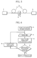
- a fusion-spliced portion X is formed by fusion-splicing the end face of the MFD-enlarged SMF 1 and that of the dispersion compensating optical fiber 2 to make one connection line L 0 .
- connection line L 0 One end of the connection line L 0 is connected to a light source 4, and the other of which is connected to a power meter 5. Then, the fusion-spliced portion X of the connection line L 0 is disposed in a heat treatment apparatus 6, and the fusion-spliced portion X is heated with the burner flame.
- connection loss in the fusion-spliced portion X is calculated at every moment. At the time when the calculated connection loss is less than a target value of the connection loss, the burner flame heating is stopped.
- two optical fibers of different kinds are set in a discharge heat treatment apparatus so that a main discharge is applied to them, and the two optical fibers are fusion-spliced (step S 1 ).
- an image of the formed fusion-spliced portion is picked up by a camera. Furthermore, image processing is applied to the image. A plurality of pieces of information such as a luminance distribution in the fusion-spliced portion are measured (step S 2 ).
- step S 3 on the basis of the plurality of pieces of information obtained in step S 2 , the connection loss in the fusion-spliced portion is calculated.
- step S 4 the calculated value obtained in step S 3 and the target value of the connection loss are compared.
- a signal indicating that an additional discharge is needed is output to step S 5 to actuate the discharge heat treatment apparatus.
- the calculated value is judged to be smaller than the target value, a signal to stop the discharge treatment is output to the discharge heat treatment apparatus.
- Discharge conditions in the heat treatment after step S 2 are decided on the basis of information such as each MDF of optical fibers of different kinds, the calculated value of the connection loss, and the target value of the connection loss.
- step S 5 After the additional discharge in step S 5 , operations after step S 2 are repeated. At the time when the calculated value of the connection loss is judged to be equal to or smaller than the target value in step S 4 , the discharge heat treatment is stopped.
- the described two kinds of heat treatment both calculate the connection loss in the fusion-spliced portion and compare the calculated value and the target value of the connection loss to decide the time to stop the heat treatment.
- connection loss in the connection line that connects the end faces of the optical fibers of different kinds to be larger than the target value.
- connection loss in the fusion-spliced portion can not be measured directly even with the OTDR.
- the submarine optical cable is normally constituted of many optical cables connected via repeaters.
- the optical cables are interconnected and the optical cables and the repeaters are connected on the vessel.
- connection line by fusion-splicing the optical fibers of different kinds.
- connection line can be connected neither with the OTDR nor the light source and the power meter that have been described earlier.
- connection loss in the fusion-spliced portion of the submarine optical cables, there is no way but to use the described method of image processing to measure the connection loss.
- the image processing does not always provide an accurate measured value of the connection loss. It is for this reason very, difficult to decide the appropriate time to terminate the heat treatment. As a result, the insufficient heat treatment or excessive heat treatment often causes the connection loss to be larger than the target value.
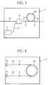
- Another example is the case of an optical amplifier 7 having a construction example shown in FIG. 7.
- the optical amplifier 7 is constituted of a plurality (four in the Figure) of SMFs 1A, an Er-doped optical fiber 2A as an optical amplifier, the light source 4, and an optical coupler 8. Both ends X, X of the Er-doped optical fiber 2A are connected with the two SMFs 1A, 1A respectively.
- the SMFs 1A and the Er-doped optical fiber 2A each have different MFD. Therefore, after fusion-splicing the two, it is necessary to apply the heat treatment to the connection points X, X to make their MFDs correspond to each other.
- the SMFs 1A are usually as short as several meters. This shortness prevents the loss in the connection points X, X from being directly measured accurately. This poses a problem that the time to terminate the heat treatment can not be decided appropriately.
- Yet another example is the case of a dispersion compensating fiber module 9 having a construction example shown in FIG. 8.
- the dispersion compensating fiber module 9 is constituted of a plurality (two in the Figure) of SMFs 2A, 2A, a dispersion compensating fiber 2B, and two connectors 10, 10 that connect the SMFs. Both ends X, X of the dispersion compensating fiber 2B are connected with the SMFs 2A, 2A respectively.
- connection loss in the connection points X, X is impossible to directly measure the connection loss in the connection points X, X with the OTDR, as in the case of the optical amplifier 7 shown in FIG. 7.
- the present invention provides a method for connecting optical fibers comprising the steps of:
- connection method A This connection method is hereafter referred to as a connection method A.
- connection method of optical fibers comprising the steps of:
- connection method B This connection method is hereafter referred to as a connection method B.
- the present invention provides a heat treatment apparatus for connecting optical fibers, the apparatus comprising:
- connection methods will be described. As described later, the connection methods of the present invention are classified into a connection method A and a connection method B.
- the connection method A is a method of connecting optical fibers of different kinds to be connected using a later-described dummy optical fiber with small connection loss.
- the connection method B is a method of connecting a plurality of optical fibers of different kinds at the same time with small connection loss.
- connection method A will be described.
- connection method A The history of development of the connection method A will be first described.
- connection loss is naturally reduced as time passes.
- connection loss immediately after the fusion splice is different in each connection line, the difference of the connection loss between each connection line is reduced as the heat treatment proceeds.
- connection loss will almost converge into a constant value determined by refractive index distributions of the optical fibers.
- connection method A has been developed in view of such considerations, and the details of which will be described below.
- optical fiber of different kind that is of the same kind as the optical fiber of different kind to be connected to is referred to as a dummy optical fiber of different kind in the following description.
- connection line One optical fiber produced by connecting the end faces of the optical fibers of different kinds to be connected to is simply referred to as a connection line, and one produced by connecting the end faces of the dummy optical fibers of different kinds is simply referred to as a dummy connection line. Further, the fusion-spliced portion of the dummy connection line is referred to as a dummy fusion-spliced portion.
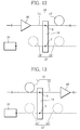
- FIG. 11 is an explanatory view for describing a first embodiment A 1 in the connection method A.
- connection line 13 is produced.
- the end face of a dummy optical fiber 11' which is of the same kind as the optical fiber 11 and that of a dummy optical fiber 12' which is of the same kind as the optical fiber 12 are fusion-spliced to form a fusion-spliced portion Y, and one dummy connection line 13' is produced.
- the dummy connection line 13' may be produced at the same time as the production of the connection line 13 or may be produced at a different time.
- connection line 13 the fusion-spliced portion X of the connection line 13 and the fusion-spliced portion Y of the dummy connection line 13' are set being arranged in parallel in a heat treatment apparatus 14.
- connection loss in the dummy fusion-spliced portion Y immediately after the fusion splice is directly measured with light of a certain wavelength.
- a value of the connection loss for deciding the time of ending the heat treatment (0.72 dB, for example) is decided.
- a difference between this value and the measured value by the OTDR 15 is determined as a target reduced amount of the connection loss ( ⁇ ).
- the value ⁇ is the target value for deciding the time of ending the heat treatment in the method A 1 .
- the heat treatment apparatus 14 is an apparatus for heating the fusion-spliced portion X and the dummy fusion-spliced portion Y, including ones with heating means using burner flame or heating means using an electric discharge.
- the heat treatment apparatus 14 is actuated, and the fusion-spliced portion X of the connection line 13 and the dummy fusion-spliced portion Y of the dummy connection line 13' are heated at the same time under the same conditions.
- connection loss in the dummy fusion-spliced portion Y is directly measured at every moment by the OTDR 15.
- connection loss in the dummy fusion-spliced portion Y is reduced. That is, the above-described value ⁇ becomes smaller.
- the operation of the heat treatment apparatus 14 is stopped to terminate the heat treatment.
- the optical fiber 11 and the dummy optical fiber 11' are of the same kind, and the optical fiber 12 and the dummy optical fiber 12' are also of the same kind. Therefore, when producing the connection line 13 and the dummy connection line 13', even if the connection loss in the fusion-spliced portions before the heat treatment does not correspond between the connection line 13 and the connection line 13' because of the misalignment of optical axes in the optical fibers being used, the heat treatment reduces the difference in the connection loss between the two and virtual nil and makes it converge to a certain value.
- the connection loss in the fusion-spliced portion X of the connection line 13 has become 0.04 dB at the time of ending the heat treatment.
- the time of ending the heat treatment is decided with the value ⁇ as the target value.
- the decision of the ending time is not limited to this mode. The following method may be applied.
- connection loss in the dummy fusion-spliced portion Y of the dummy connection line 13' is measured with the OTDP 15 at every moment.
- the measured value is compared with the preset target value of the connection loss (target value).
- target value the preset target value of the connection loss
- the heat treatment is terminated. In this mode, it is not necessary to obtain the target reduced amount of the connection loss ( ⁇ ), which can reduce the complication of operations in the heat treatment.
- the use of dummy optical fiber of different kind makes it very easy to decide the time of ending the heat treatment without giving insufficient or excessive heat treatment.
- the method A 1 can be applied when the optical amplifier 16 is disposed on the front step side of the fusion-spliced portion X of the connection line 13 as shown in FIG. 12 or when the optical amplifier 16 is disposed on the rear step side of the fusion-spliced portion X as shown in FIG. 13.
- the method A 1 can also be applied when the optical fibers of different kinds 11, 12 are connected in the dispersion compensating optical fiber module or in the optical amplifier.
- connection loss in the dummy fusion-spliced portion Y is directly measured, and the measured value is compared with the preset target value to decide the time of ending the heat treatment.
- the difference from the method A 1 is in that the connection loss in the dummy fusion-spliced portion Y is not measured directly, but indirectly.
- the measured value is compared with the preset target value to decide the time of ending the heat treatment, which is the same as in the case of the method A 1 .
- connection line 13 When the heat treatment is applied to the fusion-spliced portion X of the connection line 13 of the optical fiber of different kind, optical loss in the optical path including the fusion-spliced portion X changes in response to the reducing changes of the connection loss in the fusion-spliced portion X.
- the method A 2 is based on such findings.
- the connection line 13 is combined with the already-described dummy connection line 13', and the optical loss in the optical path of the dummy connection line 13' is measured, in order to decide the time to terminate the heat treatment according to the measured value.
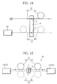
- FIG. 15 is an explanatory view for describing the method A 2 in the connection method A.
- connection line 13 is thus produced.
- the end face of the dummy optical fiber 11' which is of the same kind as the optical fiber 11 and that of the dummy optical fiber 12' which is of the same kind as the optical fiber 12 are fusion-spliced to form the dummy fusion-spliced portion Y.
- One dummy connection line 13' is thus produced.
- connection line 13 the fusion-spliced portion X of the connection line 13 and the fusion-spliced portion Y of the dummy connection line 13' are set being arranged in parallel in the heat treatment apparatus 14.
- One end of the dummy connection line 13' is connected to a light source 16, and the other end to a power meter 17.
- the heat treatment apparatus 14 is actuated, and the fusion-spliced portion X and the dummy fusion-spliced portion Y are heated at the same time under the same conditions.
- Light of a certain wavelength is introduced to the dummy connection line 13' from the light source 16.
- the power meter 17 receives the light, and measures the optical loss in the optical path from the light source 16 to the power meter 17 at every moment.
- the MFD is enlarged and the connection loss in the dummy fusion-spliced portion Y is reduced, which reduces the measured value of the optical loss.
- the obtained measured value is compared with the target value to be described later. At the time when the measured value becomes equal to or smaller than the target value, the operation of the heat treatment apparatus 14 is stopped to terminate the heat treatment.
- the above-mentioned target value is, when the fusion-spliced portion Y of the dummy connection line 13' has the connection loss preset as a target to be realized (0.1 dB or less, for example), the optical loss measured in the optical path of that dummy connection line. Its value is obtained in advance by calculation or the like.
- the optical loss in the optical path of the dummy connection line 13' is used as an indirect substitute value of the connection loss in the dummy fusion-spliced portion Y. Therefore, as in the case of the method A 1 , there is no such troublesome processing as calculating the connection loss in the connection line 13 to decide the time of ending the heat treatment and it is much easy to decide the time of ending the heat treatment.
- the heat treatment can be applied to the fusion-spliced portion X of the connection line 13 with no excess or insufficiency to reduce its connection loss.
- connection method B of the present invention will be described.
- connection method B is implemented using a plurality of connection lines, not as in the connection method A in which one connection line 13 and one dummy connection line 13' are used.
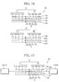
- FIG. 16 is an explanatory view for describing an embodiment B 1 in the connection method B.
- an optical fiber 11a and a corresponding dummy optical fiber 11a' For example, an optical fiber 11a and a corresponding dummy optical fiber 11a', an optical fiber 11b and a corresponding dummy optical fiber 11b', an optical fiber 11c and a corresponding dummy optical fiber 11c', an optical fiber 11d and a corresponding dummy optical fiber lid', an optical fiber 12a and a corresponding dummy optical fiber 12a', an optical fiber 12b and a corresponding dummy optical fiber 12b', an optical fiber 12c and a corresponding dummy optical fiber 12c', and an optical fiber 12d and a corresponding dummy optical fiber 12d'.
- connection lines 13a, 13b, 13c, 13d each having the fusion-spliced portions Xa, Xb, Xc, Xd are produced.
- dummy connection lines 13a', 13b', 13c', 13d' each having the dummy fusion-spliced portions Ya, Yb, Yc, Yd are produced.
- connection lines 13a, 13b, 13c, 13d and a group 13' of the dummy connection lines 13a', 13b', 13c', 13d' are arranged in the heat treatment apparatus (not shown).
- an arrangement mode is selected for the group 13 and the group 13' so that the fusion-spliced portions of each connection line in the connection line group 13 and the dummy fusion-spliced portions of the dummy connection lines corresponding to that connection lines can be heated under the same heating conditions in the heat treatment.
- each connection line and each dummy connection line are arranged in a linearly symmetric position, and if the heating means (not shown) is disposed in the central position, the fusion-spliced portion Xd of the connection line 13d and the fusion-spliced portion Yd ... of the dummy connection line 13d' can be heated under the same heating conditions, for example.
- each connection line and each dummy connection line in the group 13 and the group 13' can be arranged separately.
- the selected arranging mode should be one that would minimize the difference of heat distributions in the lines when applying the heat treatment.
- the heat treatment apparatus is actuated, and the group X of the fusion-spliced portions and the group Y of the dummy fusion-spliced portions are heated at the same time under the same conditions.
- the dummy connection line is connected to the OTDR as in the connection method A, or connected to the light source and the power meter. Furthermore, the changes of the connection loss in the heat treatment is measured directly with the light of a certain wavelength, or the changes of the optical loss is measured so as to indirectly measure the connection loss.
- connection loss or optical loss may not be measured in all the dummy connection lines, and may be measured in at least one dummy connection line.
- connection loss in the fusion-spliced portions indicate substantially the same in the plurality of connection lines. This makes it possible to know the states of reducing changes in all the connection lines with information about the reducing changes of the connection loss in at least one connection line.
- connection loss in the fusion-spliced portion (or the optical loss in the optical path) is measured using the light of a certain wavelength.
- the measured value of that time decides the time of ending the heat treatment.
- each kind of light may measure the connection loss (or the optical loss in the optical path).
- the time of ending the heat treatment may be defined as the time when all of the connection loss on each wavelength (or the optical loss in the optical path) lower to values set for each wavelength. Adopting this mode, in the optical fibers of different kinds that transmit light having a plurality of wavelengths, it is possible to provide connection lines of optical fibers of different kinds in which all the transmission loss in the light of each wavelength are suppressed to small values.
- this method B 1 a plurality of optical fibers of different kinds can be connected at the same time with small loss. As the dummy connection lines are used at that time, it is not necessary to calculate the connection loss in the connection line to be connected. This makes it very easy to decide the time of ending the heat treatment.
- the time of ending the heat treatment can be decided with the information about the connection loss in at least one dummy connection line from among the plurality of them. This simplifies information processing.
- the time of ending the heat treatment is decided without using the dummy connection lines when applying the heat treatment to the connection lines.
- FIG. 17 is an explanatory view for describing the method B 2 .
- a group 13 consisting of a plurality (four in the Figure) of connection lines 13a, 13b, 13c, and 13d is produced.
- the group 13 is arranged in the heat treatment apparatus (not shown).
- connection line 13b in the Figure One end of at least one connection line (the connection line 13b in the Figure) is connected to the light source 16, and the other to the power meter 17.
- the heat treatment apparatus is actuated, and the fusion-spliced portions Xa, Xb, Xc, Xd of each connection line are heated at the same time under the same conditions.
- the power meter 17 receives the light, and measures the optical loss in the optical path from the light source 16 to the power meter 17.
- Adopting this method B 2 is effective in the following point.
- the connection loss in all the optical fibers that constitute the ribbon-shaped optical fibers (or the optical loss in the optical paths) is not measured.
- all the optical fibers can be provided with small-loss connection.
- connection loss in the fusion-spliced portions immediately after the fusion-splice because of, for example, the misalignment of the optical axes
- the difference becomes smaller as the heat treatment progresses.
- the connection loss of both will converge into a certain value.
- the time of ending the heat treatment can be decided without using the dummy connection lines, which facilitates the heat treatment. Furthermore, it is not necessary to calculate the connection loss in the fusion-spliced portion. This simplifies the deciding of the time of ending the heat treatment.
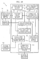
- FIG. 18 is a block constitutional view showing an example D of the heat treatment apparatus according to the present invention.
- a basic constitution of this apparatus D is an element D 0 surrounded by a broken line in FIG. 18.
- the element D 0 comprises a heating section D 1 , a connection loss measurement section D 2 , a connection loss measured value capturing section D 3 , and a decision section D 4 for deciding the time of ending the heat treatment.
- the heating section D 1 is provided with an optical fiber placing part. What is set in this is the connection line composed by fusion-splicing the optical fibers of different kinds to be connected to, or the above-described dummy connection line composed by fusion-splicing the dummy optical fibers of different kinds together with that connection line.
- This heating section D 1 is provided with heating means for applying the heat treatment to the fusion-spliced portions of those connection lines (or dummy connection lines).
- the heating means there are means using the burner flame, and means using the electric discharge, for example.
- the following description takes the discharge heating means as an example.
- connection loss measurement section D 2 is connected to both ends of the connection line.
- it is constituted of the light source and the power meter, and measures the optical loss in the optical path from the light source to the power meter.
- the measured value is input to the measured value capturing section D 3 as the indirect connection loss in the fusion-spliced portion of the connection line.
- connection loss measurement section D 2 is measuring the connection loss in the dummy connection line indirectly.
- connection loss measurement section D 2 is measuring the connection loss in at least one of them indirectly.
- the measured value capturing section D 3 captures at every moment the measured value measured in the connection loss measurement section D 2 , that is, the indirect connection loss.
- the measured value is captured at every moment by the decision section D 4 at the time of ending the heat treatment.
- a value of the connection loss to be realized is stored in advance as the target value in the above decision section D 4 .
- the target value and the measured value captured at every moment from the measured value capturing section D 3 are compared and calculated.
- a decision is made to end the heat treatment, and its signal is output to a heat treatment control section D 5 to be described later.
- the heat treatment operation of the heating section D 1 is terminated via the heat treatment control section D 5 .
- the heat treatment apparatus D further comprises various elements as follows.
- the heat treatment apparatus D is provided with a fusion splice control section D 6 .
- a preset program for the fusion splice is set in the fusion splice control section D 6 .
- a discharge control is carried out for fusion-splicing the optical fibers of different kinds placed in the optical fiber placing portion of the heating section D 1 .
- the MFDs of both optical fibers of different kinds that are fusion-spliced almost correspond at times.
- the heat treatment does not need to be effected after that. No instruction is sent from the heat treatment control section D 5 to the heating section D 1 to operate the heat treatment.
- a heat treatment necessity judgment section D 7 is incorporated in the apparatus D.
- the necessity judgment section D 7 is incorporated in order to judge whether or not additional heat treatment is necessary for the connection loss in the dummy fusion-spliced portion of the formed dummy connection line or for the connection loss in the fusion-spliced portion of at least one connection line from among those formed.
- the necessity judgment section D 7 recognizes that the fusion-splicing has finished on the basis of operation information of fusion splice control section D 6 . Immediately, the necessity judgment section D 7 captures the measured value of the connection loss in the produced connection line (or dummy connection line) from the measured value capturing section D 3 .
- the captured measured value and a preset connection loss value, that is, the target value of connection loss to be realized, are compared and calculated.
- the necessity judgment section D 7 decides to carry out the heat treatment continuing from the fusion-splicing, and outputs an indication of the decision to the heat treatment control section D 5 .
- the heat treatment continuing from the fusion-splicing is judged to be unnecessary, and the connection operation is finished.
- the heat treatment control section D 5 controls the following heat treatment.
- the heat treatment control section D 5 instructs a discharging portion (not shown) incorporated in the heating section D 1 to apply a pulsing voltage, and has the intermittent discharge heat treatment applied to the fusion-spliced portion of the connection line (or dummy connection line).
- a discharging time in one discharge zone, discharge intensity, and discharge interrupting time in the intermittent discharge at that time are decided in advance.
- the intermittent discharge heat treatment is carried out under those conditions.
- the apparatus D has the heat treatment necessity judgment section D 7 incorporated therein. Only when the necessity judgment section D 7 judges that the heat treatment is necessary for the fusion-spliced portion, the heat treatment is carried out. Therefore, the heat treatment is never started unnecessarily when it is not needed.
- the apparatus D has a calculation section D 8 for calculating connection loss reduced amount incorporated therein.
- the calculation section D 8 recognizes that the heat treatment is performed on the basis of the operation information of the heat treatment control section D 5 . Furthermore, the calculation section D 8 captures at every moment the measured value of the connection loss in the connection line (or the dummy connection line) from the measured value capturing section D 3 . The reduced amount of the connection loss is calculated from the measured value before the start of the discharging in one discharge section and the measured value of the connection loss caused by the discharge heat treatment in that discharge zone.
- the calculated value is output to a discharge conditions change section D 9 .
- the discharge conditions change section D 9 captures the calculated value during the heat treatment, and compares and calculates it with the preset target value of the connection loss reduced amount.
- the discharge conditions change section D 9 judges to change the discharge conditions for the next one discharge zone, and outputs an instruction to change the discharge conditions to the heat treatment control section D 5 .
- the heat treatment control section D 5 instructs the heating section D 1 to carry out the intermittent discharging based on the discharge conditions for a change that is previously given.
- the discharge conditions for a change is a discharge condition which has been changed to lower energy per unit time given to the fusion-spliced portion of the connection line (or the dummy connection line).
- it is a discharge condition in which the discharging time for one discharge zone is changed to be short, the discharge intensity is changed to be lowered, or the discharge interrupting time is changed to be longer.
- these changes of the discharge conditions one of those from the discharging time, discharge intensity, and discharge interrupting time may be changed, or two or more may be changed.
- the apparatus D can prevent the excessive heat treatment from occurring; for example, at the start of the heat treatment, intensified discharge heat treatment is carried out to largely change the connection loss in the fusion-spliced portion toward the target value; and at the time when the connection loss has approximated to the target value, a weak discharge is performed.
- the apparatus D has an outside diameter measurement section D 10 , a force applying section D 11 , and an outside diameter change amount calculation section D 12 incorporated therein.
- the outside diameter measurement section D 10 captures the images of the fusion-spliced portion of the connection line (or the dummy connection line), and applies image processing to them, and measures the outside diameter of the fusion-spliced portion during the heat treatment at every moment.
- the force applying section D 11 has a constitution capable of applying a traction force or a pushing force in an axial direction of the connection line (or the dummy connection line) that is disposed in the optical fiber placing portion of the heating section D 1 .
- the calculation section D 12 captures the outside diameter size of the fusion-spliced portion of the connection line (or the dummy connection line), that is, the measured value of the outside diameter size before the heat treatment, from the outside diameter measurement section D 10 .
- the calculation section D 12 recognizes that the heat treatment is carried out on the basis of the operation information of the heat treatment control section D 5 , the calculation section D 12 captures at every moment the measured value of the outside diameter size of the connection line (or the dummy connection line) measured by the outside diameter measurement section D 10 .
- the calculation section D 12 calculates a difference between the measured value and the above-described measured value before the heat treatment, and calculates an outside diameter change amount ( ⁇ D).
- the calculated value is output to a correction instruction section D 13 for outside diameter change amount.
- a value in the certain tolerance range of the outside diameter change amount is stored in advance in the correction instruction section D 13 for outside diameter change amount.
- the correction instruction section D 13 compares and calculates the value in the tolerance range and the calculated value of the outside diameter change amount ( ⁇ D) captured from the calculation section D 12 .
- the correction instruction section D 13 instructs the force applying section D 11 to apply the traction force or pushing force to the connection line (or the dummy connection line).
- the correction instruction section D 13 instructs the force applying section D 11 to apply the pushing force to the fusion-spliced portion of the connection line (or the dummy connection line).
- the correction instruction section D 13 instructs the force applying section D 11 to apply the traction force to the fusion-spliced portion of the connection line (or the dummy connection line).
- the apparatus D comprises the correction instruction section D 13 for the outside diameter change amount as described above, which is for the outside diameter change that is part of factors of increased connection loss in the fusion-spliced portion. This ensures the minimized connection loss.
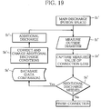
- the outside diameter size of the fusion-spliced portion of the connection line (or the dummy connection line) produced in step S' 2 is measured by the outside diameter measurement section D 10 .
- the apparatus D captures the measured value.
- step S' 3 the connection loss in the fusion-spliced portion of the connection line (or the dummy connection line) is measured by the connection loss measurement section D 2 .
- the apparatus D captures the measured value.
- step S' 4 the heat treatment necessity judgment section D 7 compares and calculates the size relation between the measured value of the connection loss and the target value previously stored.
- the measured value is judged to be larger than the target value, it means that the connection loss is large and it is judged that the heat treatment is necessary to lower the connection loss.
- step S' 5 it is judged whether or not a correction of the outside diameter change amount should be made for the fusion-spliced portion of the produced connection line (or the dummy connection line) and it is judged whether or not the discharge condition needs to be changed. On the basis of the judgment result, control operations will be carried out in step S' 6 .
- step S' 4 the heat treatment ending time decision section D 4 judges whether or not to finish the heat treatment.
- an operation of step S' 5 follows.
- step S' 5 when the correction instruction section D 13 for the outside diameter change amount judges to correct the outside diameter change amount of the fusion-spliced portion of the connection line (or the dummy connection line), the correction instruction section D 13 for the outside diameter change amount controls the force applying section D 11 in step S' 6 , and the outside diameter change amount of the fusion-spliced portion of the connection line (or the dummy connection line) is corrected.
- the discharge conditions change section D 9 judges to change the discharge conditions in step S' 5
- the discharge condition is changed in step S' 6 .
- an additional discharge is performed in step S' 7 .
- the time of ending the heat treatment can be decided simply and appropriately without causing excessive or insufficient heat treatment to the fusion-spliced portion.
- the heat treatment is carried our using the electric discharge, there might be some differences in the process of the heat treatment as the discharge condition is changed depending on environmental conditions (temperature, humidity or atmospheric pressure, for example) or the deterioration degree of electrode pole bolts.
- the heat treatment is carried out while monitoring at every moment the connection loss in the fusion-spliced portion of the connection line (or the dummy connection line), and the time of ending the heat treatment is decided on the basis of the measured value of the connection loss. This ensures the provision of the connection lines of the optical fibers of different kinds that are connected with small loss.
- this apparatus D when there is a change in the outside diameter of the fusion-spliced portion of the connection line (or the dummy connection line) during the heat treatment, there are measures taken to correct the outside diameter change amount. It is therefore possible to restrict the problem of increased connection loss caused by the outside diameter change.
- the discharge conditions change section D 9 there is provided the discharge conditions change section D 9 . If the discharge condition for the heat treatment is set on the assumption that the discharge condition is not changed during the heat treatment, the discharge conditions change section D 9 may be omitted. In that case, the connection loss reduced amount calculation section D 8 may be omitted.
- connection loss measurement section D 2 of the apparatus D is constituted of the light source and the power meter.
- the connection loss measurement section D 2 may be constituted of the OTDR to directly measure the connection loss in the dummy connection line by the OTDR.
- the outside diameter change amount calculation section D 12 and the correction instruction section D 13 for the outside diameter change amount are provided according to necessity and may be omitted.
- the necessity judgment section D for the heat treatment in the apparatus D. This can be omitted.
- the heat treatment is unnecessary, even if the heat treatment is started, the heat treatment is terminated immediately because the apparatus D is provided with the heat treatment ending time decision section D 4 for deciding the time of ending the heat treatment. This prevents excessive heat treatment.
- the apparatus D illustrates one example of the apparatus that provides the heat treatment using the electric discharge.
- the present invention can be applied to an apparatus that provides the heat treatment using burner flame. In that case, it is possible to obtain optical fibers of different kinds with small loss, as in the case of the apparatus D.
Landscapes
- Physics & Mathematics (AREA)
- Engineering & Computer Science (AREA)
- Plasma & Fusion (AREA)
- General Physics & Mathematics (AREA)
- Optics & Photonics (AREA)
- Mechanical Coupling Of Light Guides (AREA)
Abstract
Description
| | | | | | | |
| Average value (dB) | 0.84 | 0.59 | 0.73 | 0.06 | 0.04 | 0.03 |
| Maximal value(dB) | 1.01 | 0.68 | 0.82 | 0.07 | 0.05 | 0.04 |
| Minimum value(dB) | 0.62 | 0.42 | 0.58 | 0.05 | 0.03 | 0.03 |
| Standard deviation(dB) | 0.124 | 0.086 | 0.065 | 0.006 | 0.007 | 0.005 |
Claims (15)
- A method for connecting optical fibers comprising the steps of:producing a connection line in which a fusion-spliced portion is formed by fusion-splicing end faces of optical fibers of different kinds each having a different mode field diameter;producing a dummy connection line in which a dummy fusion-spliced portion is formed by fusion-splicing end faces of dummy optical fibers of different kinds which are of the same kind as said optical fibers of different kinds;arranging the fusion-spliced portion of said connection line and the fusion-spliced portion of said dummy connection line in parallel, and applying heat treatment to said fusion-spliced portion and said dummy fusion-spliced portion under the same heating conditions while measuring only connection loss in said dummy fusion-spliced portion; andfinishing said heat treatment at the time when a measured value of the connection loss in said dummy fusion-spliced portion is equal to or less than a preset target value.
- The method for connecting optical fibers according to claim 1 further comprising the steps of:measuring the connection loss in said dummy fusion-spliced portion on a plurality of light wavelengths, and finishing said heat treatment at the time when all the measured values of each light wavelength are equal to or less than the preset target value for each light wavelength.
- The method for connecting optical fibers according to claim 1 or 2 further comprising the steps of:arranging a group of the fusion-spliced portions of a plurality of said connection lines and a corresponding group of the dummy fusion-spliced portions of a plurality of said dummy connection lines in parallel, and when applying the heat treatment to all of them at the same time, measuring the connection loss in at least one dummy fusion-spliced portion from among the group of said dummy fusion-spliced portions, and finishing said heat treatment at the time when its measured value is equal to or less than the preset target value.
- The method for connecting optical fibers according to any one of claims 1 to 3, wherein
said connection loss is measured directly by an OTDR. - The method for connecting optical fibers according to any one of claims 1 to 3 further comprising the steps of:connecting a light source to one end of said dummy connection line and a light power meter to the other end, and making light incident on said dummy connection line from said light source and measuring optical loss in an optical path between said light source and said light power meter by said power meter, and utilizing indirectly the measured value as a signal indicating the connection loss in said dummy fusion-spliced portion.
- A method for connecting optical fibers comprising the steps of:producing a plurality of connection lines in which fusion-spliced portions are formed by fusion-splicing end faces of optical fibers of different kinds each having a different mode field diameter;applying heat treatment to all the fusion-spliced portions of the plurality of said connection lines while measuring optical loss in an optical path including the fusion-spliced portion of at least one of the plurality of said connection lines; andfinishing said heat treatment at the time when a measured value of said optical loss is equal to or less than a preset target value.
- A method for connecting optical fibers comprising the steps of:producing a plurality of connection lines in which fusion-spliced portions are formed by fusion-splicing end faces of optical fibers of different kinds each having a different mode field diameter;applying heat treatment to all fusion-spliced portions of the plurality of said connection lines while measuring optical loss in optical paths including the fusion-spliced portions of at least two of the plurality of said connection lines; andfinishing said heat treatment at the time when differences of measured values of said optical loss converge into a preset tolerance range.
- The method for connecting optical fibers according to claim 3, 6 or 7, wherein
said dummy connection line is a ribbon-shaped optical fiber connection line. - The method for connecting optical fibers according to any one of claims 1 to 8, wherein
said heat treatment is the one using an electric discharge. - The method for connecting optical fibers according to any one of claims 1 to 8, wherein
said heat treatment is the one using burner flame. - A heat treatment apparatus for connecting optical fibers comprising:a heating section for applying heat treatment to a fusion-spliced portion of a connection line in which said fusion-spliced portion is formed by fusion-splicing end faces of optical fibers of different kinds each having a different mode field diameter;a connection loss measurement section for measuring connection loss in said fusion-spliced portion;a measured value capture section for capturing measured values from said connection loss measurement section at every moment; anda heat treatment ending time decision section in which a target value of the connection loss in said fusion-spliced portion is stored in advance, for capturing said measured value from said measured value capture section, and comparing and calculating said target value and said measured value, and instructing said heating section the decision to finish the heat treatment at the time when said measured value is equal to or less than said target value.
- The heat treatment apparatus for connecting optical fibers according to claim 11, wherein
said heating section has discharge heating means for applying an intermittent discharge treatment to said fusion-spliced portion,
and, comprising
a connection loss reduced amount calculation section for calculating a reduced amount of the connection loss in said fusion-spliced portion in the discharge treatment per one discharge zone on the basis of the measured value from said connection loss measurement section; and
a discharge conditions change section in which a target value of the reduced amount of the connection loss caused by one time of the discharge treatment is stored, for capturing a calculated value from said connection loss reduced amount calculation section, and comparing and calculating said target value and said calculated value, and instructing said heating section to change at least one condition from among a discharge intensity, a discharge interrupting time, and discharging time for the next time of discharge treatment. - The heat treatment apparatus for connecting optical fibers according to claim 11 or 12 comprising:an outside diameter measurement section for measuring an outside diameter size of said fusion-spliced portion, and a force applying section for applying a traction force or a pushing force to said connection line; andan outside diameter change amount calculation section for calculating a change amount of the outside diameter size of said fusion-spliced portion at the time of the heat treatment on the basis of the measured value from said outside diameter measurement section; anda correction instruction section for the outside diameter change amount in which a target value of said outside diameter change amount is stored in advance, for capturing the calculated value from said outside diameter change amount calculation section, and comparing and calculating said target value and said calculated value, and instructing said force applying section to apply the traction force or pushing force to said connection line when said target value is different from the calculated value and correcting said outside diameter change amount.
- The heat treatment apparatus for connecting optical fibers according to claim 12 or 13 further comprising:a heat treatment necessity judging section in which a reference value of the connection loss to judge whether the heat treatment is needed for said fusion-spliced portion is stored in advance, for comparing and calculating said measured value from said connection loss measurement section and said reference value, and instructing said heating section to operate the heat treatment when said measured value is larger than the reference value.
- The heat treatment apparatus for connecting optical fibers according to any one of claims 11 or 14, wherein said heating section is provided with an optical fiber placing section for placing a plurality of said connection lines.
Applications Claiming Priority (2)
| Application Number | Priority Date | Filing Date | Title |
|---|---|---|---|
| JP2001200756A JP3756940B2 (en) | 2001-07-02 | 2001-07-02 | Dissimilar optical fiber connecting method and dissimilar optical fiber connecting part heat treatment apparatus |
| JP2001200756 | 2001-07-02 |
Publications (2)
| Publication Number | Publication Date |
|---|---|
| EP1273940A2 true EP1273940A2 (en) | 2003-01-08 |
| EP1273940A3 EP1273940A3 (en) | 2004-11-24 |
Family
ID=19037826
Family Applications (1)
| Application Number | Title | Priority Date | Filing Date |
|---|---|---|---|
| EP02014094A Withdrawn EP1273940A3 (en) | 2001-07-02 | 2002-07-02 | Method for connecting optical fibers, and heat treatment apparatus used therefor |
Country Status (3)
| Country | Link |
|---|---|
| US (1) | US6866428B2 (en) |
| EP (1) | EP1273940A3 (en) |
| JP (1) | JP3756940B2 (en) |
Families Citing this family (8)
| Publication number | Priority date | Publication date | Assignee | Title |
|---|---|---|---|---|
| JP2003075678A (en) * | 2001-09-07 | 2003-03-12 | Fujikura Ltd | Fusion splicing method and fusion splicing apparatus for multi-core optical fiber |
| WO2005124409A1 (en) | 2004-06-22 | 2005-12-29 | Fujikura Ltd. | Connecting method and structure of photonic crystal fiber |
| WO2012064736A1 (en) * | 2010-11-09 | 2012-05-18 | Adc Telecommunications, Inc. | Testing of optical cable using optical time domain reflectometry |
| JP5303618B2 (en) * | 2011-09-02 | 2013-10-02 | 株式会社フジクラ | Fusion splicer and optical fiber discrimination method |
| KR101235177B1 (en) * | 2012-09-03 | 2013-02-20 | 일신테크(주) | Optical fiber interface adapter for carrying along |
| WO2018097256A1 (en) | 2016-11-25 | 2018-05-31 | 住友電気工業株式会社 | Optical fiber line and optical fiber line manufacturing method |
| CN108897096A (en) * | 2018-08-30 | 2018-11-27 | 严公厂 | The testing integrated machine of fused fiber splice-OTDR |
| CN114815256B (en) * | 2022-04-15 | 2023-10-03 | 青岛虚拟现实研究院有限公司 | Screen parameter adjustment method, device and storage medium of virtual reality head-mounted device |
Family Cites Families (14)
| Publication number | Priority date | Publication date | Assignee | Title |
|---|---|---|---|---|
| JPS5535350A (en) * | 1978-09-05 | 1980-03-12 | Nippon Telegr & Teleph Corp <Ntt> | Optical fiber fusion splicing method |
| GB8810286D0 (en) * | 1988-04-29 | 1988-06-02 | British Telecomm | Connecting optical waveguides |
| JPH026908A (en) * | 1988-06-24 | 1990-01-11 | Hitachi Cable Ltd | Fusion splicing method for optical fiber |
| JP2804355B2 (en) * | 1990-08-17 | 1998-09-24 | 日本電信電話株式会社 | Control method for mode field diameter expansion of optical fiber |
| DE59309338D1 (en) * | 1992-08-07 | 1999-03-11 | Siemens Ag | Method for determining the position of optical fibers and device for carrying out the method |
| JPH0784142A (en) * | 1993-06-28 | 1995-03-31 | Furukawa Electric Co Ltd:The | Optical fiber fusion splicing method |
| JPH0727942A (en) * | 1993-07-12 | 1995-01-31 | Nippon Telegr & Teleph Corp <Ntt> | Fiber connect module |
| JP3093092B2 (en) * | 1994-03-09 | 2000-10-03 | 沖電気工業株式会社 | Optical fiber connection method |
| JP3333647B2 (en) * | 1994-09-13 | 2002-10-15 | 東京特殊電線株式会社 | Multi-fiber optical fiber cable fusion splice heater |
| SE511966C2 (en) * | 1997-06-09 | 1999-12-20 | Ericsson Telefon Ab L M | Method and apparatus for jointing the ends of two optical fibers of different type with each other |
| US6275627B1 (en) * | 1998-09-25 | 2001-08-14 | Corning Incorporated | Optical fiber having an expanded mode field diameter and method of expanding the mode field diameter of an optical fiber |
| SE514476C2 (en) * | 1998-12-18 | 2001-02-26 | Ericsson Telefon Ab L M | Method for estimating loss in a joint made between two optical fibers |
| US6565269B2 (en) * | 2001-02-07 | 2003-05-20 | Fitel Usa Corp. | Systems and methods for low-loss splicing of optical fibers having a high concentration of fluorine to other types of optical fiber |
| JP2002365466A (en) * | 2001-06-05 | 2002-12-18 | Sumitomo Electric Ind Ltd | Optical fiber connection method |
-
2001
- 2001-07-02 JP JP2001200756A patent/JP3756940B2/en not_active Expired - Lifetime
-
2002
- 2002-07-01 US US10/188,649 patent/US6866428B2/en not_active Expired - Lifetime
- 2002-07-02 EP EP02014094A patent/EP1273940A3/en not_active Withdrawn
Also Published As
| Publication number | Publication date |
|---|---|
| US20030021554A1 (en) | 2003-01-30 |
| JP3756940B2 (en) | 2006-03-22 |
| JP2003014973A (en) | 2003-01-15 |
| EP1273940A3 (en) | 2004-11-24 |
| US6866428B2 (en) | 2005-03-15 |
Similar Documents
| Publication | Publication Date | Title |
|---|---|---|
| US6275627B1 (en) | Optical fiber having an expanded mode field diameter and method of expanding the mode field diameter of an optical fiber | |
| JP3574578B2 (en) | Apparatus and method for equalizing transmission characteristics in wavelength division multiplexed optical communication system | |
| US6866428B2 (en) | Method for connecting optical fibers, and heat treatment apparatus used therefor | |
| CA1318025C (en) | Method of testing spliced portion of optical fibers | |
| US20220352980A1 (en) | Communication apparatus identification device, optical fiber connection system, communication apparatus identification method, and optical fiber connection method | |
| US7037004B2 (en) | Optical fiber component for spot size transition and method of making the same | |
| Zheng | Automated alignment and splicing for multicore fibers | |
| US6729777B2 (en) | Optical fiber splicing method and optical transmission line | |
| US5897803A (en) | Optical fiber attenuator made by fusion splicing offset fiber ends with extended heating after fusing | |
| EP0531937A1 (en) | Method of manufacturing and evaluating an optical fiber coupler and apparatus therefor | |
| EP4488730A1 (en) | Multicore fiber connecting device and multicore fiber connecting method | |
| US20030108307A1 (en) | Optical attenuator employing a fusion splice | |
| US6860119B2 (en) | Optical fiber splicing method | |
| Tanabe et al. | The latest fusion splicing technologies supporting innovation of fiber optics | |
| CN101098191B (en) | Photosignal source device for implementing adjustable optical signal-to-noise ratio and controlling means | |
| US7228049B2 (en) | Optical fixed attenuator and process and apparatus for producing the same | |
| JP2000275469A (en) | Optical fiber fusion splicing method | |
| JP4115295B2 (en) | Optical fiber connection method | |
| JP2783392B2 (en) | Optical fiber alignment method | |
| TW202102887A (en) | Method of splicing optical fibers and structure of spliced optical fiber | |
| JP2001116949A (en) | Optical fiber fusion splicing method | |
| JPH095207A (en) | Evaluation method of fusion spliced part of different diameter core optical fiber | |
| JP2000098173A (en) | Method of forming material-bonded joint between optical fibers | |
| CN121634398A (en) | Core alignment fusion splicing device and fusion parameter optimization method for soft glass active optical fiber | |
| US20020044337A1 (en) | Techniques for making an insertion loss correction in an optical fiber amplifier |
Legal Events
| Date | Code | Title | Description |
|---|---|---|---|
| PUAI | Public reference made under article 153(3) epc to a published international application that has entered the european phase |
Free format text: ORIGINAL CODE: 0009012 |
|
| AK | Designated contracting states |
Kind code of ref document: A2 Designated state(s): AT BE BG CH CY CZ DE DK EE ES FI FR GB GR IE IT LI LU MC NL PT SE SK TR |
|
| AX | Request for extension of the european patent |
Free format text: AL;LT;LV;MK;RO;SI |
|
| PUAL | Search report despatched |
Free format text: ORIGINAL CODE: 0009013 |
|
| AK | Designated contracting states |
Kind code of ref document: A3 Designated state(s): AT BE BG CH CY CZ DE DK EE ES FI FR GB GR IE IT LI LU MC NL PT SE SK TR |
|
| AX | Request for extension of the european patent |
Extension state: AL LT LV MK RO SI |
|
| STAA | Information on the status of an ep patent application or granted ep patent |
Free format text: STATUS: THE APPLICATION IS DEEMED TO BE WITHDRAWN |
|
| AKX | Designation fees paid | ||
| 18D | Application deemed to be withdrawn |
Effective date: 20050203 |
|
| REG | Reference to a national code |
Ref country code: DE Ref legal event code: 8566 |