EP1273922A1 - Gerät und Verfahren zur Strommessung - Google Patents
Gerät und Verfahren zur Strommessung Download PDFInfo
- Publication number
- EP1273922A1 EP1273922A1 EP01116436A EP01116436A EP1273922A1 EP 1273922 A1 EP1273922 A1 EP 1273922A1 EP 01116436 A EP01116436 A EP 01116436A EP 01116436 A EP01116436 A EP 01116436A EP 1273922 A1 EP1273922 A1 EP 1273922A1
- Authority
- EP
- European Patent Office
- Prior art keywords
- electrode
- voltage
- current
- interference
- signal
- Prior art date
- Legal status (The legal status is an assumption and is not a legal conclusion. Google has not performed a legal analysis and makes no representation as to the accuracy of the status listed.)
- Granted
Links
Images


Classifications
-
- G—PHYSICS
- G01—MEASURING; TESTING
- G01R—MEASURING ELECTRIC VARIABLES; MEASURING MAGNETIC VARIABLES
- G01R19/00—Arrangements for measuring currents or voltages or for indicating presence or sign thereof
- G01R19/0023—Measuring currents or voltages from sources with high internal resistance by means of measuring circuits with high input impedance, e.g. OP-amplifiers
-
- A—HUMAN NECESSITIES
- A61—MEDICAL OR VETERINARY SCIENCE; HYGIENE
- A61B—DIAGNOSIS; SURGERY; IDENTIFICATION
- A61B5/00—Measuring for diagnostic purposes; Identification of persons
- A61B5/05—Detecting, measuring or recording for diagnosis by means of electric currents or magnetic fields; Measuring using microwaves or radio waves
- A61B5/055—Detecting, measuring or recording for diagnosis by means of electric currents or magnetic fields; Measuring using microwaves or radio waves involving electronic [EMR] or nuclear [NMR] magnetic resonance, e.g. magnetic resonance imaging
-
- A—HUMAN NECESSITIES
- A61—MEDICAL OR VETERINARY SCIENCE; HYGIENE
- A61B—DIAGNOSIS; SURGERY; IDENTIFICATION
- A61B5/00—Measuring for diagnostic purposes; Identification of persons
- A61B5/145—Measuring characteristics of blood in vivo, e.g. gas concentration, pH value; Measuring characteristics of body fluids or tissues, e.g. interstitial fluid, cerebral tissue
- A61B5/1455—Measuring characteristics of blood in vivo, e.g. gas concentration, pH value; Measuring characteristics of body fluids or tissues, e.g. interstitial fluid, cerebral tissue using optical sensors, e.g. spectral photometrical oximeters
-
- A—HUMAN NECESSITIES
- A61—MEDICAL OR VETERINARY SCIENCE; HYGIENE
- A61B—DIAGNOSIS; SURGERY; IDENTIFICATION
- A61B5/00—Measuring for diagnostic purposes; Identification of persons
- A61B5/24—Detecting, measuring or recording bioelectric or biomagnetic signals of the body or parts thereof
- A61B5/25—Bioelectric electrodes therefor
- A61B5/279—Bioelectric electrodes therefor specially adapted for particular uses
- A61B5/291—Bioelectric electrodes therefor specially adapted for particular uses for electroencephalography [EEG]
-
- A—HUMAN NECESSITIES
- A61—MEDICAL OR VETERINARY SCIENCE; HYGIENE
- A61B—DIAGNOSIS; SURGERY; IDENTIFICATION
- A61B5/00—Measuring for diagnostic purposes; Identification of persons
- A61B5/24—Detecting, measuring or recording bioelectric or biomagnetic signals of the body or parts thereof
- A61B5/316—Modalities, i.e. specific diagnostic methods
- A61B5/318—Heart-related electrical modalities, e.g. electrocardiography [ECG]
-
- A—HUMAN NECESSITIES
- A61—MEDICAL OR VETERINARY SCIENCE; HYGIENE
- A61B—DIAGNOSIS; SURGERY; IDENTIFICATION
- A61B5/00—Measuring for diagnostic purposes; Identification of persons
- A61B5/24—Detecting, measuring or recording bioelectric or biomagnetic signals of the body or parts thereof
- A61B5/316—Modalities, i.e. specific diagnostic methods
- A61B5/369—Electroencephalography [EEG]
-
- G—PHYSICS
- G01—MEASURING; TESTING
- G01R—MEASURING ELECTRIC VARIABLES; MEASURING MAGNETIC VARIABLES
- G01R19/00—Arrangements for measuring currents or voltages or for indicating presence or sign thereof
- G01R19/0046—Arrangements for measuring currents or voltages or for indicating presence or sign thereof characterised by a specific application or detail not covered by any other subgroup of G01R19/00
- G01R19/0053—Noise discrimination; Analog sampling; Measuring transients
Definitions
- the present invention concerns methods and devices for measuring and/or injecting electrical currents, in particular in the presence of strong fields, as e.g. magnetic field gradients.
- small currents are currents, which are changed due to the line capacitance depending in particular on the length of the line.
- Small currents are generated or used e.g. with detectors or sensors (as e.g. photodiodes, currents sensors etc.), in an experimental setup or in a technological process. Additional problems arise, if the currents have to be measured or injected in the presence of strong disturbing fields or influences, e. g in NMR, cooling or vacuum devices.
- detectors or sensors as e.g. photodiodes, currents sensors etc.
- the monkey is placed in a static homogenous magnetic field with a strength of 4.7Tesla which is created by a cylindrical, superconducting, upright coil.
- the resonance frequency of the precessing protons is 200MHz in our magnet. Short periodic RF-pulses with the same centre frequency excite the protons in the brain. The emitted signal is subsequently detected with a weight on different relaxation times.
- the RF-coil is placed near the brain area of interest, in our case the area around the electrode tip. Therefore, the coil is placed around the chamber. How the RF-pulses cause interference problems is discussed later.
- the gradient tube inside the magnet bore contains three room temperature coils, the gradient coils.
- Each gradient coil is able to create a magnetic field with a well defined gradient in each one of the three directions in space.
- These magnetic field gradients define the element of volume in the brain in which the BOLD-signal is measured.
- the gradient coils generate interferences which are of no use for imaging.
- the power amplifiers which drive the gradient coils have pulse-width modulated switching output stages with a clock frequency of 81kHz.
- the gradient fields are modulated with this clock frequency which induces further interference problems.
- the metal-microelectrodes typically used are made of sharpened platinum-iridium-wire, which is coated with glass.
- the tip of the wire is left uncoated and forms a small electrolytic capacitor with the tissue of the brain which has similar electrical properties as water with 0.9% NaCl (Saline).
- the capacity forms at the transition zone between the metal and the fluid. Therefore, the electrode acts in first approximation as a capacity and is coupled to the neuronal signal sources through this capacity.
- the magnitude of the capacity depends on the size of the uncoated tip. It is common practice in neurophysiology to measure the impedance of the electrode in Ohm at 1kHz to indicate the size of this capacity. Electrodes with an impedance range from e.g. 100 to 300k ⁇ are utilized which corresponds to a capacity range from 500 to 1500pF.
- the ground connection to the animal is made of a massive metal piece which is placed in the recording chamber.
- This chamber is made of non-conducting synthetic material and is implanted directly onto the skull.
- the electrode is advanced into the brain through the recording chamber and a small drilled hole in the skull.
- the chamber is filled with Agar which is prepared with Saline (deuterium-water+0.9% NaCl).
- Saline deuterium-water+0.9% NaCl
- the measuring set-up is very sensitive to electric and magnetic interference fields because the output resistance of the signal source is high and the voltages to be measured are small. Therefore, booths are commonly used which are specially designed to shield the animal, the electrode and the preamplifier from undesired interference fields emitted from the surrounding area. The booths also serve as a shield against radio-frequency fields. These RF-fields are able to degrade the low-frequency recording amplifiers. Usually the cable between the electrode and the preamplifier is short. This avoids signal loss in a long cable and, at the same time, diminishes the picking-up of interference from the surrounding area.
- the small high-resistance signal which emerges from the electrode is fed into the preamplifier directly nearby.
- the strong magnetic fields from the gradient coils would permeate all the electrical circuits of the preamp and make its proper function impossible.
- the RF-pulse source close to the preamp would cause problems.
- the gradient fields also induce voltages in the electrode cable itself.
- the magnitude of the voltage depends among other things on the size of the loop area that the electrode line forms with the ground line.
- a common method to avoid induction voltages is to twist the lines or to use rotational symmetric cables. Doing this, the effective loop area is ideally zero and thus the induction voltage equals 0V. We use the latter method continuously. All the way until inside the recording chamber the ground line encircles the electrode and the electrode line. But it appeared that even a non-perfect rotational symmetry suffices to generates interference voltages of a not acceptable strength. In order to minimize this remainder of interference the "Near" Interference Compensation Circuit described in chapter 0 was developed.
- the signal from the electrode is amplified, digitalised, recorded and than analysed over a large frequency band from near DC to 3kHz.
- the gradient interference has a structured periodic pattern it can be removed from the neuronal signal after digitalisation and recording with a mathematical approach, the principal components analysis. That can be done under the condition that the linear transmission of the gradient noise and the neuronal signal is secured all the way through from the first amplification stage to the output of the ADC. Neither the electrode amplifier nor the ADC is allowed to saturate during gradient switching.
- the amplitude of the gradient noise is much higher than the neuronal signal it would be necessary to chose such a small amplification that the ADC does not saturate. In this case the recorded neuronal signal has such a low resolution that a lot of neuronal information is lost. Therefore, two compensation techniques were developed to minimize the gradient noise before the electrode signal gets amplified. Then the amplification can be set as high as possible but to a value that will not result in the saturation of the ADC for sure.
- the invention is generally capable to be implemented in all applications for measuring and/or injecting electrical currents.
- the electrical currents manipulated according to the invention can comprise dc or ac currents with a certain bandwidth.
- the invention is implemented with ac currents showing small high-frequency current changes.
- the concepts of the invention are described by way of example with respect to the simultaneous measurement of fNMR images and recording of electrophysiological potentials.
- the simultaneous measurement of fNMR images and recording of electrophysiological potentials of animals or human beings is a further subject of the invention.
- the invention has particular advantages.
- ( r ) The combination of fMRI with single and multiple electrode recordings in the anesthetized and behaving monkey is an ideal approach for systems neuroscience, as the two techniques are complementary, providing us with information on two different spatio-temporal scales.
- the electrodes have excellent spatio-temporal resolution but very poor coverage, while fMRI can yield important information on a larger spatio-temporal scale.
- Optical imaging of activity-dependent intrinsic signals has great spatio-temporal resolution (approximately 50 microns), and would appear to have both very good resolution and some coverage. Yet it is limited to the cerebral surface and it has proved very difficult to apply in the alert, behaving monkey, as it requires the replacement of dura mater with artificial, transparent materials, an operation that had extremely limited success.
- the invention presents the first simultaneous intracortical recordings of neural signals and fMRI responses.
- the inventors compared local field potentials (LFP), single- and multi-unit spiking activity with high spatio-temporal blood-oxygen-level-dependent (BOLD) fMRI responses from the visual cortex of monkeys.
- LFP local field potential
- BOLD blood-oxygen-level-dependent
- the largest magnitude changes were observed in LFPs, which at recording sites characterized by transient responses, were the only signal that significantly correlated with the hemodynamic response.
- Linear systems analysis on a trial-by-trial basis showed that the impulse response of the neuro-vascular system is animal- and site-specific, and that LFPs yield a better estimate of BOLD than the multiunit responses.
- the capacitance of the cable between the electrode and the amplifier in our case 200pF for a 2m cable
- the impedance of the electrode itself act as a voltage divider that reduces the signal with increasing impedance and cable length.
- the Recording Technique makes it possible that the transmission bandwidth from the electrode to the amplifier is not reduced by the long coaxial cable and that no energy is required for recharging the capacitance of the cable.
- C2V current-to-voltage
- the 600pF input capacitance (due cable length), together with the high-impedance feedback resistance, form a low-pass filter in the feedback circuit of the preamp, which reduces the phase margin (each amp defines the maximum phase shift that can be achieved without causing an oscillatory behavior at the amp's output) of the feedback at frequencies higher than the cut-off frequency so dramatically that the circuit becomes instable.
- PI controller Proportional-Integral controller
- the tuning parameters (amplification and cut-off frequency) of the PI controller were set for the desired cable length by applying a test square-wave input signal across a 1Mohm resistor. They were adjusted to provide the fasted impulse response while yielding minimum overshoot.
- the input current flows across a large resistance, and the voltage drop is equal to the output voltage of the converter.
- the output voltage of the circuit is adjusted such that the input voltage equals 0V.
- the input resistance of the converter is effectively 0 Ohm and the voltage at the output end of the resistor, with respect to ground, is equal to the voltage drop across the resistor.
- the voltage across the inputs of the converter is amplified using a low-noise DC voltage amplifier with a fixed gain.
- the input current of the amplifier is negligible.
- the output voltage of the amplifier provides the actual-value signal for the PI controller.
- the set point is the ground potential.
- the PI controller adjusts the voltage on the output end of the resistor such that the output voltage of the amplifier equals 0V. In so doing, the input voltage of the converter is also adjusted to 0V. No current flows through the voltage amplifier, and, as a result, all of the current flows across the resistor. The voltage drop across the resistor can be tapped off from the output of the controller. Current flowing into the converter appears as a negative voltage at the output.
- the voltage at the output of the feedback resistor i.e. the converted signal, can be loaded and used as the input signal to further stages.
- the compensation of interference can best be described by distinguishing between the origin of the interfering signal, i.e. close to the tip of the electrode and far from the tip of the electrode.
- the capacitance measured between the ground of the chamber and the animal's fluids is not zero. All currents induced into the "animal” will be capacitively coupled to the electrolyte within the chamber (we used 0.9% salt & agar in deuterium as ground; agar was used to avoid oscillations of the dura), and thus to the recording system's ground. This type of interference originates from a distance greater than that of the electrode-tip to the electrode ground.
- Interference in the physiological signal due to capacitive coupling is actively compensated by a sensor built into the electrode assembly. It eliminates or greatly reduces all interference originating for sources more than a few centimeters away from the electrode.
- a simple electrical model of the animal is a conductor coupled to its environment through a number of capacitances. These capacitances are the metal-liquid transition zones around the animal. Firstly, the animal is coupled to the ground of the electrode through a very large capacitance. Secondly, the neuron (i.e. our current source), is coupled to the electrode through smaller capacitance ( ⁇ 500pF), which represents the resistance of the electrode.
- IV and ECG lines, eye irrigation lines, and SpO2 sensors were found to be strong sources of interference, by forming large loops sensitive to magnetic interference.
- Currents flowing because of such interference will pass through an effective electrode-to-animal-fluid capacitor to the electrode, because of the non-zero metal-to-fluid capacitance mentioned above (interference signals generated in the animal flow both across the electrode and the ground in accordance with their respective capacitances).
- a third contact namely the sensor electrode, is present near the electrode and has a lower capacitance to the animal than the ground of the electrode ( Figure 0.2).
- the current between the sensor and the ground is measured, amplified and converted into a voltage.
- the voltage is inverted, amplified again in two steps with integrated output current limitation for the protection of the animal (10mA max, 2V max) and sent back to the animal through a junction electrode in the cavity of the mouth. This compensation secures that the current flowing back to the animal is just big enough to adjust the current into the sensor electrode to 0 A.
- the magnetic-field sensor is composed of three small, identical, orthogonally-oriented coils positioned near the electrode.
- the voltages induced in the coils by the gradients serve as the inputs to the compensation circuit.
- These signals are amplified and passed through a further amplification stage where the gain can be adjusted with a precision potentiometer to a value between -1 and 1.
- the sum of the three independently adjusted signals serves as the reference of the current-to-voltage converter.
- the orthogonal orientation of the small coils and the adjustability of value and sign of the gain make it possible to simulate the induction voltage in a wire loop of any given diameter and orientation (vector addition).
- FIG. 0.3 shows the assembly if electrophysiological and imaging devices used for simultaneous imaging and single or multiple unit data.
- the above methods ensure a non-saturated, measurable signal which, however, is still contaminated by the gradient interference.
- the elimination of the rest interference was accomplished by applying two standard mathematical, dimensionality reduction methods, namely those of Principal and Independent Component Analysis (PCA and ICA respectively) techniques.
- PCA and ICA Principal and Independent Component Analysis
- the data are realigned to the segment onset pulse (signifying the beginning of collection of single K-Space segment), reshaped into an N by M matrix, where N is the number of segments and M is the number of data points acquired while digitizing the physiology signal.
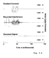
- PC or IC analysis of such data and elimination of those components that best correlate with the directly recorded interference resulted in a "clean" signal as shown in Figure 0.4.
- Figures 0.1 to 0.3 show further details of the recording hardware: (0.2, 0.3) Recordings were conducted with glass-coated platinum-iridium electrodes. Their holder consisted of three concentric, metallic cylinders, the innermost serving as the contact point for the electrode, the middle as the far-interference sensor, and the outermost as the amplifier ground (see Methods). The cylinders were insulated from each other by layers of PEEK. Electrode, sensor and ground were connected to the amplifier with two twisted, coaxial cables (middle panel). The electrode was positioned by manually turning a screw with a fine thread pitch. In addition, a three-coil magnetic-field sensor was mounted on the microdrive to compensate for near interference (see Methods). The RF coil used for imaging was placed around the chamber.
- FIG. 1 A block diagram of the recording and compensation circuitry.
- the animal can be conceived as being capacitively connected to any metal contact, including connections to ground (C g ), sensor (C s ), and electrode (C e ). Because of the finite animal-to-ground capacity, a fraction of the interference currents flow through the electrode. To compensate for such currents we used a sensor built into the electrode holder (Current Sensor). Interference originating in the vicinity of the electrode tip or within the electrode holder and the cables was compensated for by using three small, identical, orthogonally-oriented coils positioned near the electrode (Magnetic Field Sensor). C2V, Current to voltage converter; ADC, analog to digital converter, PIC, proportional integral controller.
- C2V Current to voltage converter
- ADC analog to digital converter
- PIC proportional integral controller.
- RF coils of 30-80 mm diameter were used ( Figure 0.3) which were optimized for increased sensitivity over a given region of interest (ROI) such as a portion of the primary visual cortex or regions of areas V2, V3, V4 and V5 (MT).
- ROI region of interest
- MT regions of areas
- pick-up coils being arranged at the gradient coil cables are used. All images were acquired using a 96mmx96mm field of view (FOV). T1-weighted, high resolution (256x256, 0.5mm thickness) anatomical scans were obtained using the 3D-MDEFT pulse sequence (modified driven equilibrium Fourier transform, see Ugurbil,K. et al.
- Imaging at high magnetic fields initial experiences at 4 T. Magnetic Resonance Quarterly 9, 259-277 (1993)), with an echo time (TE) of 4 msec, repetition time (TR) of 14.9 msec, flip angle (FA) of 20 deg, and 4 segments.
- TE Echo time
- TR repetition time
- FA flip angle
- 4 segments 4 segments.
- TE 8.9 msec
- TR 2000 msec
- FOV 96mmx96mm
- a 512x384 matrix reconstructed to 512x512
- slice thickness 0.5mm.
- Multi-slice fMRI was carried out by using multi-shot (segmented) gradient-recalled echo planar imaging (GE-EPI) 49 .
- GE-EPI gradient-recalled echo planar imaging
- the segments were acquired separately 20 and merged into one image by sorting all k-space lines according to their phase. In these segmented acquisitions, echo time shift (ETS) was used to minimize ghosting.
- ETS echo time shift
- aqt matrix-size / (2 * spectral width)
- Electrophysiological Recording All recording hardware, including electrodes, microdrives, signal conditioning and interference compensation devices, were developed in house (N.K.L., A.O. and M.A., in preparation). A plastic chamber (see Supplementary information) formed to fit the animal's skull precisely was implanted over the occipital pole during an aseptic surgical procedure. The skull inside the chamber was left intact. At the beginning of each experiment a 2mm trephination was performed through which the electrode was introduced into the brain. Electrodes were made of platinum-iridium (Pt 90 Ir 10 ) wire etched with sodium cyanide (NaCN) solution and coated with glass (Corning glass 7570).
- Pt 90 Ir 10 platinum-iridium
- NaCN sodium cyanide
- the glass-coated tip was glued into a glass capillary tube (1.5mm outer diameter) with super glue.
- the wire extended 5-10mm beyond the end of the capillary tube and served as the contact point for the electrode.
- the electrode holder ( Figure 0.2) consisted of three concentric, metallic cylinders (copper beryllium, CuBePbS or a bronze alloy, CuSn 7 PbZn).
- the innermost cylinder served as the contact point for the electrode, the middle as far-interference sensor, and the outermost layer as the amplifier ground (see below).
- the cylinders were insulated from each other with layers of Polyetheretherketone.
- the concentric cylinders offer the additional advantage of being a rotation-symmetric shield for the electrode, permitting optimal ground contact to the animal while avoiding any kind of loops susceptible to induction.
- the gap between electrode and electrode holder was sealed with silicon gel. Electrode, sensor and ground were connected to the amplifier with two twisted, coaxial cables. The outer conductor of both cables was connected to the ground cylinder of the electrode holder. The electrode holder was held firmly in a microdrive attached to the recording chamber via a holding ring. The positioning of the electrode was accomplished by manually turning a screw with a thread pitch of 700 ⁇ m. In addition, a three-coil magnetic-field sensor (see below & Figure 0.1) was mounted on the microdrive.
- the joints between microdrive, holding ring and chamber were sealed with silicon gel.
- the chamber was filled with deuterium saline (0.9% NaCl in D 2 O) to provide electrical contact between the ground cylinder and the animal.
- Deuterium saline was used instead of regular saline to avoid changing the RF coil's Q-factor and to permit optimal shimming.
- 0.6% agar was added to the saline to minimize oscillations in both the saline and the dura during the readout gradient alternations.
- the electrode was lowered into visual cortex and positioned such that both signal intensity and stability were maximized. Based on the anatomical MR images most recordings were obtained from granular and infragranular layers of V1.
- the output voltage equals the voltage drop across the 10MOhm resistor and is therefore proportional to the measured input current. Furthermore, no signal loss occurs by charging the cable capacity.
- the tuning parameters (amplification and cut-off frequency) of the PI controller were adjusted with a square-wave current.
- Interference sources Two types of interference had to be compensated for: interference originating from a distance greater than that from the electrode tip to the electrode ground ( far interference), and interference originating from the immediate vicinity of the electrode tip ( near interference).
- This compensation set the voltage of the mouth electrode so that the current flowing through the sensor electrode remained 0A.
- the mouth current equaled the sign-inverted interference current flowing to the animal.
- the three capacitances Figure 0.1 are parallel, setting the sensor current to zero forces all the other currents to zero as well, thereby eliminating the interference measured at the tip of the electrode and leaving the neural signal unaffected.
- this method is effective against induction currents due to the distance between the electrode tip and ground (possibly because of eddy currents in the saline in the recording chamber and in the brain).
- the operation principle of this circuit is as follows.
- the voltages induced in the coils serve as the inputs to the compensation circuit.
- These are amplified and passed through an additional amplification stage, where the gain can be adjusted with a precision potentiometer to a value between -1 and 1.
- the sum of the three independently adjusted signals serves as the reference (ground) for the current-to-voltage converter.
- the orthogonal orientation of the small coils and the adjustability of sign and value of the gain make it possible to simulate the induction voltage in a wire loop of any given diameter and orientation (vector addition).
- a virtual wire loop that has opposite sense of winding can be adjusted by the precision potentiometers in such a way that the remaining loops, caused by asymmetries in electrode holder and cable, are effectively compensated.
- Neural Data Analysis Signals were amplified by 3-30 mV/pA. In a conventional voltage measuring system using an electrode of 300kOhm impedance measured at 1kHz, this would amount to a total amplification of 10 4 -10 5 .
- the bandwidth of the main amplifier was 50mHz to 3kHz (12dB/oct and 18dB/oct respectively) and the signal was digitized with 22.3kHz using a 16-bit AD converter, set to +/-10V input range. It was subsequently decimated by a factor of three to 7.43kHz.
- the above interference reduction techniques ensured a non-saturated, measurable signal that, however, was still contaminated with a certain amount of gradient interference.
- the elimination of the residual interference was accomplished by applying a standard mathematical dimensionality reduction method, the principal component analysis (PCA) technique.
- the data were initially realigned to the slice-selection pulse (signifying the beginning of collection of an image of a single K-space segment for single- or multi-shot acquisitions, respectively), and subsequently reshaped into an N by M matrix, where N was the number of segments and M was the number of data points acquired while digitizing the physiology signal.
- the preamplifier is normally mounted as close to the electrode, and thus the animal's head, in order to keep the cable capacitance low. In doing so the switching magnetic fields induce voltages in every loop both inside and outside the preamplifier. Even the use of miniature electronic components cannot adequately minimize the total surface in which voltages can be induced within a standard preamplifier.
- the appropriate shielding can help to reduce interference, however, while many options exist for shielding against electrical interference, very few options exist for shielding against magnetic interference.
- the materials normally used for this purpose e.g., mu metal
- a number of low-frequency voltage amplifiers possess the undesirable characteristic of rectifying high-frequency voltage signals coupled with the input signal.
- the rectified interference signal appears in the output signal.
- the effect occurs for coupling at the signal input stage, as well as at the operating voltage input and signal output stages of the amplifier.
- the amplifier rectifies the 200MHz excitation pulse of the NMR pulse sequence.
- Our measurements showed that under the conditions presented by our magnet such an amplifier is quickly fully saturated and needs several tens of milliseconds to recover after the signal has subsided.
- the addition of a high-frequency filter to every lead would only lead to additional surfaces, or loops, in which the gradient fields would induce voltages.
- the electrode behaves like a capacitor with 200pF, which corresponds to an impedance of 800kOhm at 1kHz. In this case the cable capacitance of 200pF would lower the signal amplitude by a factor of two. The reduction would be independent of the frequency. 2) An electrode with 200kOhm. The reduction would be 20%.
- the ground connection is made of a bronze alloy (CuSn7PbZn, wstnr. 2.1090) and is placed annular around the electrode wire.
- the electrical contact to the skull is made with the aid of a mixture of agar (0.6%) with deuterium water and 0.9%NaCl which is filled in the recording chamber.
- the concentric ground connection serves also as a shield for the electrode wire against electric interference fields from outside the recording chamber.
- the electrode holder proceeds to two coaxial cables without any interruption of the shielding. A sort of cable is used which does not show the microphonic effect, that means it does not produce any electric currents if it is exposed to mechanical vibrations. Such vibrations occur strongly inside the magnet during the switching of the gradients.
- a feed-through for the electrode cable is mounted at the bottom of the animal chair.
- This feed-trough is designed in order to short-circuit the shielding of the electrode cable with the animal chair for RF-currents but isolate it for low frequencies.
- An annular capacitor which spreads out from the cable shielding over the mounting plate of the animal chair serves for that purpose. This formation ensures a very low impedance at high frequencies because the annular capacitor does not include any connection wires which would have an inductivity and , as a consequence, a high impedance for RF-currents.
- This RF-short-circuit avoids the trespass of RF-interference into the magnet, which can disturb imaging, and, at the same time, prevents parts of the RF-excitation pulse from reaching the measuring amplifier via the electrode cable.
- One thing to think of would be to ground the animal by connecting the electrode ground to the grounded mounting plate. But as we will see later only the configuration described here allows recordings from more than one electrode.
- the feed-through in the mounting plate for the sensor cable is designed in the same way like the one for the electrode cable.
- the amplifier ground is connected with the chassis of the amplifier.
- the amplifier ground is not connected with protective earth.
- the "Far" Interference Compensation Circuit which will described later, determines the potential of the amplifier ground with respect to the earthing potential.
- the first is the amplifier ground, which is connected to the ground of the electrode holder (it is represented by the simple three-cornered symbol in the circuit diagram).
- the second is the ground of the outputs which are represented by the three-cornered symbol with the appendix "iso".
- the latter is normally set to earth potential by the connected instruments.
- the RF-Coil is isolated from the animal. Thus, no low-frequency currents are able to flow to the animal.
- the shielding of the RF-cable and the RF-resonance circuit is connected to the magnet and thus to earth potential.
- the Ringer-Lactate-solution conducts at a frequency of 50Hz well enough to transmit interference currents to the animal which are coupled capacitively into the infusion line outside the magnet.
- Interference currents which are coupled into the infusion line are drained away to earth potential by a thin silver wire (20cm long, 0.5mm diameter) inside the infusion line.
- the eye lids of the animal are kept open with two specially designed plastic specula.
- they are constantly irrigated with saline through small openings in the specula by an infusion pump.
- the irrigating saline conducts interference currents towards the animal.
- a silver wire earth s interference currents.
- the body temperature is maintained with a heating pad. Distilled water is running through the heating pad forming a circular flow.
- the problems caused by the heating pad are minor compared to the ones originating from the infusion and the eye irrigation line.
- the heating pad is isolated from the animal and the water conducts much worse than the saline. Therefore, the heating pad is not presented in the diagram. Nevertheless, measures were taken to earth also the water inside the heating pad.
- Two clews of silver wire are placed inside the water hose near the feed-trough into the animal chair to achieve good contact to the water. The two silver wires are connected to earth potential.
- SpO2-sensors produce electrical interference fields at a frequency of about 1kHz and contribute to a dynamic ground loop (see chapter 1.1) with their capacitance to the skin of the animal. The far interference compensation is able to remove both interference effects.
- An Sp02-sensor (Model 8600V, Nonin Medical Inc., Madison MN USA) operating with fibre-optic components was utilized that does not contain any conducting materials and, therefore, does not present any problems with electrical interference.
- the record-stimulation control circuit (see figure 2) serves the following purposes :
- the isolated control input is accomplished with the opto-coupler TIL111 from Texas Instruments. R1 and D1 protect the LED of the opto-coupler against a voltage overload at the input. If the "Stim Control"-switch is set to “Extern” the transistor of the coupler operates with the resistor R2. In the position “Off” the electrode is permanently connected to the i2uc. In the position “Continuous” the electrode is permanently connected to the stim current source. In “Off” or “Continuous” mode the external control is deactivated.
- the comparators U2 and U3 switch at the zero-crossing of the collector voltage.
- the comparators U4, U5 and U6 analyse the two delayed signals.
- the resulting signals control the driving circuits (Q2, Q3) for two relays which perform the switching successions claimed in point 5.
- the comparators U7 and U13 and the transistor Q1 are not used here and can serve for future circuits.
- the relay RL1 (S2-24V from NAIS-Matsushita) is configured as a change-over switch and switches the electrode either to the i2uc or to the stim current source. In the current-free case of the relay coil the input of the i2uc is open (point 4). To ensure the drop-out of the relay during the fall of the supply voltages both supply voltages of the first op-amp (which has to be protected) of the i2uc are analysed. Comparator U8 with the resistors R11 to R14 and the zener diode D2 compares the positive supply voltage with the zener voltage and deactivates the relay RL1 as soon as the supply voltage drops from nominal +15V below +14V. Comparator U9 with R15, R16 and D3 compares the negative supply voltage of nominal -7.5V with the zener voltage and deactivates the relay RL1 as soon as the supply voltage increases to more than -6.2V.
- the relay RL2 is closed in the current-free case so that eventually connected stim current sources are short-circuited if the instrument is switched off. This accomplishes an increased protection of the electrode.
- the comparators U10, U11 and U12 analyse the control signals and control the LED's which display the actual state of the switches.
- a high quality relay for change-over switching for the electrode is utilized. It has a sufficiently high isolation resistance between the relay coil and its contacts. Furthermore, the contacts generate low noise. Both properties help to minimize interferences during recording.
- the current measurement makes it possible that the transmission bandwidth from the electrode to the amplifier is not reduced by the long coaxial cable and that no energy is required for recharging the capacitance of the cable. If in case of current measurement a voltage loss at the input of the amplifier can be avoided, as a consequence, no energy is lost in the capacitance of the cable and no current from the electrode is necessary to recharge that capacitance .
- the electrode is connected with the operational amplifier (op-amp) U1 through the relay RL1 (figure 3).
- the function of RL1 is described in chapter 4.
- the op-amp AD743 must be protected from input voltages that are beyond its supply voltages.
- the diode network D1-D6 serves for that purpose. It limits the input voltage to a range from -2V to +2V.
- the maximum constant input current must not exceed 200mA.
- no special steps are necessary for the protection of the input of the amplifier during the handling of the device, e.g. changing of the electrodes.
- the circuit in chapter 4 takes care of the separation of the op-amp input from the electrode line.
- We used low-leakage diodes of the type BAS45 to avoid the injection of reverse current into the op-amp input during normal operation.
- the 600pF input capacitance due to the length of the cable, and the high-impedance feedback resistance form a low-pass filter in the feedback circuit (cut-off frequency here 27Hz) that reduces the phase margin of the feedback at frequencies higher than its cut-off frequency so dramatically that the circuit becomes instable.
- the first stage amplifies only a voltage it can be optimised for minimal noise. This provides a better signal to noise ratio for the PI controller.
- the i2uc (see figure 3) consists of a voltage amplifier with U1, a PI controller with U2 and the resistor R6.
- the voltage at the electrode line is amplified by a factor of 20 in the circuit consisting of U1, R1, R2 and R3.
- the op-amp AD743 from Analog Devices provides a very low-noise voltage amplification.
- the direct current fed into the electrode is negligible due to its FET input stage. This input stage also limits the current noise outwards the non-inverting input connection.
- the power supply rejection of the negative supply voltage of the AD743 was not sufficient to suppress the noise of the regular negative supply voltage to the desired level. That noise is generated by the voltage controller LM320-15 in the power supply unit (figure 6).
- the circuit designed with U3 generates a low-noise negative supply voltage of -7.5V for the AD743. These -7.5V are generated from the regular negative supply voltage by means of the resistors R12 and R13. R14 and C3 form a low-pass filter which blocks off the noise below the cut-off frequency of 0.016Hz.
- the op-amp U3 is wired as a unity-gain follower.
- the component parts R16, R17 and C4 provide the stable operation of the op-amp at the power supply bypassing capacitor of the AD743.
- the thermal noise (Johnson noise) inherent to a resistor can be measured connecting a resistance greater than 100kOhm to the input. There is good correspondence between the measured (using the oscilloscope's high pass at AC setting as lower cut-off frequency, 10Hz) and theoretical values. In case of a 1MOhm resistor the noise current is 8pA rms , with 100kOhm 19pA rms . The measured values deviate more from the theoretical values with resistances smaller that 100kOhm. This is probably due to the fact that they are approaching the value of the non-ideal internal resistance of the current-voltage converter, which is 30kOhm at higher frequencies, see below. If the electrode is considered as an ohmic resistance between 100kOhm and 1MOhm, then the resolution of the amplifier is nearly as good as theoretically possible.
- the following PI controller consists of the op-amp OP37 and the components R7, C2 and R8.
- the output voltage of the voltage amplifier referred to the voltage across the 1 ⁇ -resistor R1 provides the control deviation. That voltage (not ground) represents the reference voltage for the i2uc.
- the design used here allows to feed a voltage change into the electrode cable. This possibility serves for the "Near" interference compensation (see chapter 10) to impress a compensating voltage into the cable.
- the same compensation circuit can couple a current into the electrode cable through the 15pF-capacitor C1.
- the 10M ⁇ -resistor R6 connects the output of the controller with the input of the voltage amplifier.
- the PI controller adjusts the voltage at the output end of the resistor such that the output voltage of the voltage amplifier equals 0V. In so doing, the input voltage of the converter is also adjusted to 0V. No current flows into the voltage amplifier, and, as a result, all of the current flows across the resistor R6. The voltage drop across the resistor can be tapped off from the output end of the controller. Current flowing into the converter appears as a negative voltage at the output. The voltage at the output of the feedback resistor, i.e. the converted signal, can be loaded and used as the input signal for further stages.
- the proportional and integral tuning constants of the PI controller are set for a particular cable length.
- the components C2 and R8 which are determined experimentally define these constants. This is accomplished by feeding in a test square-wave signal into the circuit via the cable that will be used in the actual experiment.
- the current source are approximated with a square-wave voltage generator and a 1M ⁇ resistor.
- the tuning constants (amplification and cut-off frequency) are adjusted to provide the fasted impulse response while yielding minimum overshoot at the output end of the controller.
- a step-by-step description of the whole procedure can be found in [Tietze, U. and Schenk, C., "PI-Regler,” Halbleiter-Scenstechnik 4 ed. 1978, pp. 673-676].
- control parameters in the current device are adjusted in dependence of the cable capacitance and the electrode impedance.
- the following stage refers the output voltage of the PI controller to ground potential and amplifies it by a factor of 100.
- U4 the high-speed video difference amplifier AD830 from Analog Devices.
- the difference amplifier contains two voltage-to-current converters (v2ic's), marked with Gm, and a voltage amplifier with gain 1.
- the input signal of the first v2ic is the output voltage of the controller.
- the feedback of the output voltage of U4 into the second v2ic with R9 and R10 yields a total amplification of 100.
- the switch S1 can shunt R10 and R11 and, in doing so, reduce the amplification to a tenth.
- the capacitor C5 reduces the amplification at high frequencies with a cut-off frequency of about 7.2kHz.
- This prefilter is inserted to avoid the saturation of the amplifier when high-frequency disturbing currents penetrate the electrode cable.
- An example for these disturbing currents is the modulation frequency of the pulse-width modulated gradient power amplifiers of our NMR system which is 81kHz. Through the gradient coils this frequency generates a disturbing current in the electrode cable. The overall gain of our device up to this stage results in 10 9 V/A.
- a low-pass filter with a cut-off frequency of 3kHz follows the i2uc (figure 5).
- the filter is designed as a third order Bessel filter.
- the Bessel characteristic guarantees very good square-wave transmission properties with little overshoot.
- the calculation of the component values is described in the literature, e.g. [Tietze, U. and Schenk, C., "Aktive Filter,” Halbleiter-Scenstechnik 4 ed. 1978, pp. 266-326.].
- a high-pass filter follows which can be switched on as required.
- This filter is used only in cases in which a high DC current emerging from the electrode loads the dynamic range of the AD-converter too much which would require a reduction of the amplification.
- the lower cut-off frequency of 50mHz is low enough that no necessary information is lost in the recorded signal.
- the design of this filter is second order Bessel.
- gain 1, 2, 3, 6, 10, 20, 30, 60 or 100.
- the different values in small steps make it possible to best utilize the dynamic range of the AD-converter for the maximum resolution.
- a stepless adjustment with a potentiometer was rejected to ensure that the amplification does not drift or jump during physiological recordings. This is a very important point for the subsequent software processing of the data, namely the cleaning from the gradient noise.
- the next stage allows the external muting of the output signal by means of a TTL signal applied to an isolated strobe signal input. This was done in preliminary experiments to mask off parts of the output signal which were strongly disturbed by the gradient switching noise. For that purpose we used the CMOS analog switch IC HI-303 from Harris (old model). As described in chapter 0, the control signal has to be galvanic separated. This is accomplished in the same way shown in chapter 4.
- the output signal must be galvanic separated.
- the isolating amplifier ISO122 from Burr-Brown is used with the necessary high dynamic range (> +/-10V). This component does not function like an opto-coupler. It transforms the input signal into a duty-cycle modulated signal and digitally transfers that one across the insulating barrier by means of small 1pF capacitors.
- the output stage of the ISO122 converts the signal back into an analog voltage with the same amplitude as the input voltage.
- the passive low pass at the output end filters the carrier frequency of 500kHz originating from the digitalisation process.
- the output is short-circuit proof and has an output resistance of 600 ⁇ . In spite of all the precautions taken, the isolating amplifier still has a noticeable noise level.
- the gain of the main amplifier should be set at least to 3 in order to have the noise of the i2uc at a significant level at the output of the device.
- V out -10 9 V/A ⁇ I in .
- a high-pass filter determines the lower cut-off frequency of the device. If the filter is off, the entire signal, including any DC component, will be amplified.
- the high-pass filter has 2 nd order Bessel characteristics and a -3dB cut-off frequency of 0.05Hz (50mHz).
- the higher cut-off frequency is determined by a 3 rd order Bessel filter with a -3dB cut-off frequency of 3kHz.
- the device As described in 0 the device possesses two different grounds. Therefore, two power transformers are necessary that generate two independent galvanic separated supply voltages, see figure 6.
- the protective earth is not connected inside the device which renders it necessary that the insulation of the transformers meet the EU standard EN60742.
- the first transformer generates a voltage of +/-15V for the main circuit with simple voltage regulator IC's.
- Two 1 ⁇ resistors precede the regulators. They serve as safety fuse and offer the possibility to measure the supply current of the device.
- the second transformer generates the isolated supply voltage for the output stages of the isolating amplifiers. This voltage amounts to +/-15V as well and is generated with the same type of voltage regulator IC's.
- the highest interference currents in the electrode line during the switching of the gradients arise as follows:
- the gradient fields induce a voltage in all conducting loops. This induced voltage depends linearly on the area inside the loop.
- the current flowing through the loop due to the induced voltage depends on the impedance one would receive when opening the loop at any place and measuring the impedance across both ends of the open loop. In doing so, one has to take into account the impedance not only for DC but also for the whole frequency range across which the neuronal signal shall be recorded.
- the steep slopes of the gradient currents include frequency portions from near DC up to 100kHz.
- the resulting interference signal meets exactly the frequency range which is required for the neuronal recordings.
- loops have to be taken into account that contain capacitances and, thus, form a loop only for alternating currents. We call these "dynamic groundloops".
- ECG module M1001A Controller Patient Model 84, M1178A; Monitor "Anaesthesia”, Model M1094B; all Hewlett Packard
- ECG module M1001A Controller Patient Model 84, M1178A; Monitor "Anaesthesia", Model M1094B; all Hewlett Packard
- the voltages from the ECG electrodes are fed into high-pass filters, consisting of C1, R3, C2 and R4 with a time constant of 500ms.
- the next stage with U1 and U2 serves as an impedance converter and stops any current flowing from the ECG module to the ECG electrodes.
- op-amps with very small input currents.
- the output voltages of the preamplifier feed the standard connections of the ECG module.
- the resistors R9, R10 and R11 by-pass the feature of the ECG system to check the placement of the electrodes.
- the power transformer with rectifier is placed in a separate chassis. Out of reasons mentioned before, its secondary winding is not grounded.
- Standard voltage regulator IC's generate two stabilized supply voltages of +15V and -15V.
- the LED's D13 and D14 display the state of operation.
- Figure 8 gives a simplified, equivalent circuit of the monkey. This model helps to clarify the way how interference currents appear in the electrode cable and how the compensation circuit counteracts them.
- All metal-liquid transition zones can be characterized as capacitances.
- the ground connection around the electrode has a capacitance (C gnd ) towards the liquid inside the recording chamber which is in steady contact with body tissue.
- the tissue and the body liquids are considered ideally conductive.
- the layer between electrode signal line and ground contact is the interference sensor that also posses a capacitance (C se ) towards the tissue.
- the capacitance of the electrode inside the brain (C el ) is by a factor of around 100 smaller than C gnd or C se .
- C el is series-connected with a voltage source, namely the neuronal signal itself.
- the mouth electrode (explained in 9.4) with the junction capacitance C mo into the cavity of the mouth. It is made of two 0.5mm silver wires wrapped around pieces of gauze soaked with saline.
- the "Far” interference source with the capacitance C int represents all interference sources that are coupled capacitively onto the animal from the outside, including the “dynamic groundloops” (see 9.1).
- the alternating currents fed into the animal across C int flow off across C el , C se , C gnd and C mo . Since these capacitances are parallel to each other, the current is divided in accordance with their respective capacitances.
- the ground capacitance C gnd can only be increased up to a certain limit. Thus, a portion of the interference current always flows through the electrode (C el ).
- the interference current into the electrode equals zero if the total interference current coupled through C int flows off through C mo . In that case the effective interference current through the ground connection (C gnd ), the sensor contact (C se ) and the electrode (C el ) is zero.
- the current between the sensor and the ground is measured, amplified and converted into a voltage.
- the voltage is inverted, amplified and sent back to the animal through the junction electrode in the cavity of the mouth. This compensation ensures that the current flowing back to the animal is just big enough to adjust the current into the sensor electrode to 0A.
- the electrode holder is composed of two concentric metallic cylinders (copper beryllium or lager bronze, see figure 8) to minimize induced voltages.
- the innermost cylinder serves as the contact point for the electrode wire conducting the neuronal signal.
- Around the electrode and the electrode contact is the sensor electrode that serves as the input to the compensation circuit.
- the two contacts are insulated from each other through a layer of TEKAPEEK (PolyEtherEtherKetone).
- the amplifier ground is concentric to both the electrode and the sensor and forms the outermost layer of the electrode holder.
- the ground as well as the sensor that measures the interference current into the animal stay constantly in contact with the liquid inside the recording chamber.
- the current-to-voltage converter (i2uc) in the sensor circuit is very similar to that one described in 5. It has a local reference potential which is different from ground in order to disregard voltages induced between the shielding of the electrode cable and the sensor cable.
- the i2uc is designed with the bipolar op-amp U1 (OP27).
- OP27 bipolar op-amp U1
- the property of a low current noise is not needed here because the sensor impedance is by a factor of about 100 smaller than that of the electrode.
- the resistor that accomplishes the current-to-voltage conversion has only 100k ⁇ (R4) instead of 10M ⁇ .
- An interference current results in a signal of approximately the same magnitude at the output ends of both i2uc's.
- the control parameters of the PI controller are the same as in the electrode circuit.
- the next stage is again the difference amplifier AD830 (U3). It refers the output voltage of the i2uc to ground potential and amplifies it by a factor of 100. Also a prefilter is added (R9, R10, C4) with the same cut-off frequency as in the electrode amplifier.
- the components R7, R8 and C5 give the opportunity to add a DC voltage to the output voltage of the AD830 (see chapter 0).
- the transfer constant is 1:1.
- the output voltage of the AD830 feeds the isolating amplifier ISO122 where it is referred to the ground of the output stage (marked with "iso").
- ISO122 isolating amplifier
- the output voltage of the i2uc determines the control deviation of the PI controller.
- the output voltage of the controller serves as actuating variable. It generates the counter voltage between electrode holder and the mouth electrode, as described in 0.
- the controller consists of the fast op-amp U4 (AD712), the resistor R24, 11 switchable resistors and 11 switchable capacitors.
- the resistors tune the proportional component of the controller in a range from 33x10 -6 to 3.3.
- the capacitors adjust the integrating component with integration frequencies ranging from 500Hz to 50MHz.
- the parts D15, D16, D17 and R12 avoid an output phase reversal of the op-amps U4 and U6 when their input common-mode voltage range is exceeded.
- control parameters follows the method described in [B2].
- the parameters depend on many influences, e.g. the impedance of the sensor and the ground contact, the conductivity of the mouth electrode and the capacity of the animal itself towards its surroundings. Normally, the adjustments are made only once in the beginning of an experiment.
- the DC cut-off frequency can be adjusted in a range from 0.016Hz to 160Hz.
- the second stage (U6, C7, R13 and R14) amplifies the output voltage of the low pass by a factor of 6 and attenuates the amplification for frequencies higher than 1.5kHz.
- the output voltage of the second stage feeds the amplification stage of the i2uc with the AD830.
- this voltage is superimposed to the controlled variable delivered by the sensor.
- the amplification of the controller in the stationary case is decreased from infinite values to 1/6.
- the power amplifier has to fulfil high requirements:
- the output voltage of the PI controller with a maximum of 15 V is stepped down to a maximum of 1.5V with the resistors R15, R16 and R17 (point 5).
- the op-amp U5 which is wired as a unity gain buffer buffers that voltage.
- the design of the current limitation was a difficulty because in normal operating mode, i.e. with the current limitation inactive, it should have small output resistance even at high frequencies.
- the current limitation is accomplished with the diodes D9-D12 and two current sources that generate 10mA each flowing through these diodes.
- the current is divided up in two portions of 5mA in the branches D9/D10 and D11/D12.
- the input is situated between D11 and D12, the output between D9 and D10.
- the currents from the current sources with the transistors Q1 and Q2 flow in opposite directions referred to the diode network.
- no effective current flows into the input or the output and, in the unloaded case, the output voltage is equal to the input voltage.
- the output resistance is determined by the steepness of the diode characteristic at 5mA forward current and by the grade of equality of the forward characteristics. Consequently, we use the diode type 1N4448 which has tolerance values of the forward characteristic documented by the manufacturer.
- the diode D11 blocks off any current and the output is supplied with 10mA through Q1 and D9. This limits the output current to 10mA.
- the same principle is valid for negative currents.
- the components R18-R21, D13 and D14 generate the reference voltages for the current sources from the supply voltage.
- the diodes D13 and D14 minimize the temperature dependence of the transistor current sources.
- Q1 with the resistor R22, and Q2 with R23 respectively, provide the 10mA currents with the aid of the reference voltages.
- the diode D3-D8 limit the output voltage in case of a current source failure to approximately 2V (point 5).
- the switch can deactivate the compensation circuit.
- the electrode holder and the cables that are used in the experiments with animals are parts of the set-up.
- the test electrode has an impedance of 210kOhm.
- a saline bath simulates the animal.
- a silver wire similar to the mouth electrode described in chapter 0, is dipped in the saline.
- a small copper wire in the adjoined corner (about 50mm away from the silver wire) injects the interference current.
- the electrode holder is placed in a distance of 70mm to both wires.
- a voltage frequency generator and a 100kOhm resistor in series approximately represent a current source and generate the interference current. Additionally, a 10 ⁇ F capacitor is inserted in series to avoid any DC currents and electrolysis in the saline.
- the ground of the generator is connected to the same contact of the recording amplifier where normally the magnet is connected, see Fig.1.
- the generator yields a rectangular signal with 200Hz and 7V p-p which results in about 70 ⁇ A p-p interference current. As described above, a part of this current flows through the sensor and the electrode.
- the electrode amplifier is set to its lowest amplification 1*10 ⁇ 9V/A.
- the filter range is 50mHz to 3kHz.
- the amplification of the sensor monitor is 1*10 ⁇ 7V/A.
- the DC cut-off frequency is adjusted to 5Hz.
- Figure 8.1 shows the electrode current on Ch1 and the sensor current on Ch2 under five different conditions (b to f). The corresponding current strength per division is labelled accordingly.
- the time base is 1ms per division.
- Diagram a shows the interference current signal.
- the far interference compensation circuit is almost deactivated by setting the control parameters proportional amplification and integrating frequency to the lowest possible values (33x10 -6 and 500Hz).
- the interference current is adjusted to the highest possible amplitude that does not saturate the two amplifiers.
- the resulting peak-to-peak interference current is 8nA in the electrode and 2.2 ⁇ A in the sensor.
- the signal was averaged 50 times (case d) by means of an oscilloscope function.
- the electrode signal only a 200Hz sine wave (6pAp-p) remains.
- the "Far" Interference Compensation Circuit described above is able to suppress only interference currents which effect the sensor and the electrode likewise. Interference induced close to the tip of the electrode, in the electrode holder or in the leads by the switching gradient coils cannot be compensated using the circuit described above. The magnitude of this interference is too great and therefore requires a dedicated compensation circuit. This method of compensation is effective against local (near the electrode or the electrode cable) induction currents in the electrode holder and the cable which could not be completely avoided by a rotational-symmetric construction. In addition, we expect that this method is effective against induction currents due to the distance between the electrode tip and ground (eddy currents in the saline in the recording chamber and in the brain).
- the simple model in figure 9 serves to point out the functional principle of this compensation method.
- the gradient coils induce voltages in the tissue surrounding the electrode and in the non-perfect rotational symmetry of the electrode holder.
- TX1 Transformer
- the primary winding represents the gradient coil itself.
- the secondary winding is series-connected to the electrode and the neuronal signal and generates the interference voltage U1.
- An ideal voltage source represents the neuronal signal while the capacity C1 (e.g. 500pF) is a model for the electrode.
- the capacity C2 (e.g. 600pF) simulates the electrode cable to the i2uc.
- the input voltage of the i2uc is U4 and equal to 0V in the stationary case. However, the input resistance is high for the fast rising slopes which can originate from the switching gradient fields.
- the variable gain amplifier can apply a compensating voltage U3 between the shielding of the cable and the inverting input of the i2uc.
- a pick-up coil which is placed around the supply cable of the gradient coil feeds its signal into the variable gain amplifier. Gradient cable and pick-up coil form a unit in the model and are represented by the ideal transformer TX2. Assuming ideal conditions, the voltages U1 and U5 are proportional to each other.
- a voltage jump U1 is the obvious effect.
- the electrode capacity C1 and the cable capacity C2 step down U1 to the voltage U2 provided that the input resistance of the i2uc is high during the voltage jump. If the voltage U3 stays at 0V the voltage U2 drops across the input of the i2uc (U4). As a result, the i2uc drains away the charge in C2 and an interference pulse is generated.
- the variable gain amplifier can adjust the voltage U3 to the same magnitude as U2.
- variable gain amplifier must offer the opportunity to change sign of gain because the sense of winding of TX1 is not predictable. The gain of the variable gain amplifier is trimmed to minimize the magnitude of the interference.
- TX1 x , TX1 y , TX1 z The secondary windings of the three TX1 transformers (TX1 x , TX1 y , TX1 z ) are series-connected and add their respective interference signal to the electrode.
- Each one of the three pick-up coils of the three TX2 transformers (TX2 x , TX2 y , TX2 z ) has its own variable gain amplifier.
- the respective output voltages are added before they act upon the inverting input of the i2uc.
- the interferences originating from the three gradient coils and the three compensating voltages superimpose linearly and can be trimmed independently.
- the trim procedure of the three amplifiers is not trivial when the three gradient fields switch at about the same time because then it cannot be perceived from the interference signal which one of the amplifiers is still mismatched.
- the circuit is the same for each one of the three pick-up coils. Therefore, we explain the circuit only for one pick-up coil (Figure 11).
- Each pick-up coil is connected to a 50 ⁇ coaxial cable. Inside the device the 50 ⁇ -resistor R1 terminates the cable.
- a purchased RF-blocking filter (40dB attenuation at 200MHz) is supplemented with a low-pass filter consisting of the components R2 and C1 (cut-off frequency 5MHz) in order to filter out potentially intruding high-frequency interferences.
- the next stage is a voltage amplifier with a gain of 150. Like in the "Far" interference compensation this circuit must be very fast (see 0).
- a wideband current-feedback operational amplifier is utilized to ensure the high rapidity of the circuit at this high amplification.
- the bandwidth of that kind of op-amp does not depend directly on the amplification like usually in op-amp's with voltage feedback.
- the following stage can adjust the gain linearly between -1 and +1 by means of the high-precision potentiometer R5. This part of the circuit is described in literature, e.g. in [Tietze, U. and Schenk, C., "Bipolares Kocontinentenglied,” Halbleiter-Scenstechnik 4 ed. 1978, pp. 194-195.] as bipolar coefficient element.
- the op-amp AD817 from Analog Devices. It disposes of a high bandwidth and operates in the standard voltage feedback mode because no high amplifications are required.
- the resistors R7 and R8 and the potentiometer R5 together with the op-amp U2 trim the amplification between -1 and +1.
- the inductive behaviour of the wire-wound potentiometer hinders a high bandwidth of the circuit.
- the application of the capacitor C2 helps to lessen that disadvantage.
- the summation of the three output voltages, the attenuation of the signal and the low-resistance coupling into the electrode i2uc is accomplished with the resistors R10, R20, R30 and R32.
- R32 is a 1 ⁇ resistor and is connected to ground. The other end of the resistor is connected to the respective output voltages through the resistors R10, R20 and R30. Thus, each output voltage is attenuated to 1/300 of the original value and the sum can be tapped off low-resistance across the resistor R32. This voltage corresponds to U3 in 0.
- the inverting input of the i2uc is connected to the summation point between R32 and R33. The coupling into the i2uc is described in 0.
- the far and the near interference compensations are active and the peak-to-peak interference is adjusted to a minimum of 260pA by using all four potentiometers of the near interference compensation circuit.
- the amplifier gain here is set to 60*10 ⁇ 9V/A in order to take the most advantage of the ADC input range.
- the amplification is reduced to ensure unsaturated signals. No spikes caused by the fMRI-RF-pulses appear. In the first 5ms the undisturbed neuronal signal can be seen because no gradient coil are switching during this time. The sensor signal is almost zero because the controller of the far interference circuit regulates this value to zero. The same is true for case c in which the near interference compensation circuit is inactive.
- the peak-to-peak interference increases to 700pA by a factor of 2.7. Additionally, in case d the far interference compensation circuit is switched off. This results in a strong increase of the interference in the electrode signal increases to 21nAp-p by a factor of 30. Now the interference currents can also be seen on the sensor signal. In this case the output signal of the far compensation circuit is connected to the amplifier ground ( Figure 8).
- This configuration contains a big ground loop formed by the shielding of the electrode cable, the ground contact of the electrode holder, the head of the animal, the mouth electrode, the 4.7 ⁇ F capacitor and the cable to the far compensation circuit output which is connected to amplifier ground ( Figure 1). This ground loop increases the electrode interference current as described in chapter 0.
- the electrode During electric stimulation the electrode remains connected to the main recording amplifier unit.
- the stimulation current is produced by means of an external current source which is connected to an additional input at the amplifier unit.
- the electrode can be easily and fast switched between the recording amplifier or the stimulation current source, either manually or by an external control signal.
- the record-stimulation control circuit switches the electrode to the recording amplifier (Stim off) or to the external stimulation current source (Stim on) depending on the external control signal from the NMR acquisition program (ParaVision).
- the input signal is isolated by an opto-coupler.
- the unused current source (Stim off) gets short-circuited to avoid voltage build-up to the maximum compliance voltage (120V). Switching to "Stim on” this voltage would apply to the electrode instantly. This would damage the electrode and the cells as well.
- a delay circuit ensures the correct order of the switching of the relays to avoid an unloaded current source at any time.
- a voltage-to-current converter with input-to-output isolation from BAK is used ("Biphasic Stimulus Isolator Model BSI-1") as the stimulation current source.
- the current source is modified to compensate stimcurrent loss in the capacity of the long cable to the electrode.
- the circuit is described in Chapter 0. As a necessity for the "Far Interference Compensation Circuit” to work properly the current output has to be floating.
- the Far-Interference compensation circuit originally designed to minimize interference during recording generated by the switching gradients, is always active and minimizes all gradient-induced currents to less than 100nA.
- a waveform generator with voltage output (BAK Biphasic Pulse Generator Model: BPG-Z) generates the desired biphasic voltage pulses which drive the voltage-to-current converter.
- FIG 14 shows the principal circuit of the cable capacity compensation.
- the biphasic voltage pulses are isolated by an opto-coupler. Its output voltage is marked by U ge .
- U ge drives the voltage-to-current converter which drives the electrode.
- the classic current source circuit with an inverting operational amplifier is used.
- U ge is applied to the resistor R1 which generates the desired stimulation current.
- the other terminal of the resistor is set to virtual ground potential by the op-amp U1.
- the current I in flowing through R1 is equal to the output current I out which again is equal to the current I el flowing through the electrode.
- the output current I out then flows through the electrode cable with the capacity C2 to the electrode, which is represented by the resistor R4 and the capacitor C3 in parallel.
- the output current splits into two portions, I ca that charges the cable capacity and I el that flows through the electrode. Note that it is not possible to directly measure the current I ca .
- the current I ca reduces the desired current I out to the electrode.
- the principle of the correction circuit is to analyse the voltage applied to the cable, then to calculate the current which is required to charge the cable capacity and, finally, to increase the output current by that amount of current. As a consequence, the loss in the cable capacity is compensated.
- That correction current I cor is injected into the virtual ground like the input current I in .
- the current charging the cable capacity can be calculated by differentiating the voltage across the cable.
- the voltage across the cable can be taped off low-resistance from the output of the op-amp (U out ) referred to ground.
- U out serves as the input voltage of a differentiating circuit which is designed with the op-amp U2, the capacitor C1 and the resistor R3. Its output voltage is named U di .
- R2 converts this voltage into the correction current I cor .
- the values of the components in the correction circuit R2, R3 and C1 can be deduced as follows :
- the settings do neither depend on the electrode impedance, R4 and C3, nor on the shape of the stimulation pulse.
- the setting of the compensation circuit only depends on the cable length and no further adjustments are necessary in the course of a stimulation experiment.
- Figure 15 shows the output section of the voltage-to-current converter (u2ic) of the BAK "Biphasic Stimulus Isolator" Model BSI-1.
- the high output voltage op-amp PA83 from APEX is used to provide a compliance voltage of more than 100V which is, for example, required in order to drive a 1M ⁇ resistor with a current of 100 ⁇ A.
- An additional circuit which offers the opportunity to monitor the output voltage of the current source by means of a regularly earthed oscilloscope isolates the output voltage and transfers it to the ground of the input. This circuit is not shown here.
- the “isolated side" of the isolator is powered by two bipolar supply voltages of +/-125V and +/-10V, which are supplied by two switching power supply modules.
- the input voltage of the isolator is transferred to the isolated side with opto-couplers.
- the output voltage of U1A see figure ??, is proportional to the input voltage with a factor of 300mV per 1V input voltage.
- U1A drives the input of the u2ic.
- a classical inverting u2ic circuit with one op-amp U2 is used (Tietze, U. and Schenk, C., "Stromttlen für erdfill Technology,” Halbleiter-Scenstechnik 4 ed. 1978, pp. 242-243).
- the output voltage of U1A is connected through the "Range" switch SW1 to one of the resistors R1, R2, R3 or R4 which are all connected to the virtual ground provided by U2 at its inverting input and generates the output current.
- the output terminals are used interchanged compared to the original BAK configuration.
- the low-resistive output terminal (red jack) which is connected to the output of U2 now serves as the output ground and is connected to the shielding of the electrode cable. Therefore, the sign of the transfer factor of the isolator now is negative (positive input voltage provides negative output current).
- C1 ensures the stability of the u2ic if only a short cable is used to connect the electrode.
- C3 and R5 are more dominant and the circuit tends to behave like a classical integrator with the desired behaviour with regard to phase shift and amplification.
- the values of C3 and R5 were determined experimentally in order to provide circuit stability and not to degrade the usual cable capacity compensation speed.
- the values of the parts in the correction circuit can be calculated using equation (10) in chapter 0, but the correct setting is critical. If the correction circuit is trimmed for a longer cable than actually connected the circuit starts oscillating and the output current can reach undefined values which might damage brain tissue. It is indispensable to check the settings for the correct actual cable length before the electrode is positioned into the brain.
- a cable with the same capacity as the electrode cable is prepared with a 1M ⁇ resistor simulating the electrode. With that cable the cable capacity compensation is safely adjusted before each stimulation session.
- the correction circuit can be switched off by setting its amplification to zero using SW2.
- Figure 16 demonstrates the performance of the cable length compensation circuit.
- Biphasic pulses with +/-100 ⁇ A were applied to a 1M ⁇ resistor simulating the electrode.
- the voltage rises to +/-100V.
- a cable of 6m length (the same length as in the stimulation experiments) was connected.
- With the correction circuit inactive the voltage and, consequently, the current through the 1M ⁇ resistor rises slowly according to the time constant formed by the resistor and the cable capacity.
- the rise time of about 2ms (upper diagram in figure 16) is much to long to generate pulses with the desired duration of 300 ⁇ s (see lower diagram).
- With active and properly adjusted compensation circuit the rise time shrinks to about 100 ⁇ s which is sufficient to generate the desired pulse duration (see lower diagram).
Priority Applications (2)
| Application Number | Priority Date | Filing Date | Title |
|---|---|---|---|
| DE60128556T DE60128556D1 (de) | 2001-07-06 | 2001-07-06 | Gerät und Verfahren zur Strommessung |
| EP01116436A EP1273922B1 (de) | 2001-07-06 | 2001-07-06 | Gerät und Verfahren zur Strommessung |
Applications Claiming Priority (1)
| Application Number | Priority Date | Filing Date | Title |
|---|---|---|---|
| EP01116436A EP1273922B1 (de) | 2001-07-06 | 2001-07-06 | Gerät und Verfahren zur Strommessung |
Publications (2)
| Publication Number | Publication Date |
|---|---|
| EP1273922A1 true EP1273922A1 (de) | 2003-01-08 |
| EP1273922B1 EP1273922B1 (de) | 2007-05-23 |
Family
ID=8177966
Family Applications (1)
| Application Number | Title | Priority Date | Filing Date |
|---|---|---|---|
| EP01116436A Expired - Lifetime EP1273922B1 (de) | 2001-07-06 | 2001-07-06 | Gerät und Verfahren zur Strommessung |
Country Status (2)
| Country | Link |
|---|---|
| EP (1) | EP1273922B1 (de) |
| DE (1) | DE60128556D1 (de) |
Cited By (27)
| Publication number | Priority date | Publication date | Assignee | Title |
|---|---|---|---|---|
| WO2006044705A1 (en) * | 2004-10-18 | 2006-04-27 | Compumedics Usa, Inc. | Method and apparatus for buffering electrophysiological signals during an mri procedure |
| WO2006099919A1 (en) * | 2005-03-03 | 2006-09-28 | Unilever Plc | Apparatus and method for reducing interference |
| CN100425198C (zh) * | 2003-02-21 | 2008-10-15 | Ge医疗系统环球技术有限公司 | 射频屏蔽和磁共振成像系统 |
| US7844344B2 (en) | 2004-03-30 | 2010-11-30 | Medtronic, Inc. | MRI-safe implantable lead |
| US7844343B2 (en) | 2004-03-30 | 2010-11-30 | Medtronic, Inc. | MRI-safe implantable medical device |
| US7853332B2 (en) | 2005-04-29 | 2010-12-14 | Medtronic, Inc. | Lead electrode for use in an MRI-safe implantable medical device |
| US7877150B2 (en) | 2004-03-30 | 2011-01-25 | Medtronic, Inc. | Lead electrode for use in an MRI-safe implantable medical device |
| US8027736B2 (en) | 2005-04-29 | 2011-09-27 | Medtronic, Inc. | Lead electrode for use in an MRI-safe implantable medical device |
| WO2011121537A1 (en) | 2010-04-01 | 2011-10-06 | Koninklijke Philips Electronics N.V. | Signal measuring system, method for electrically conducting signals and a signal cable |
| US8280526B2 (en) | 2005-02-01 | 2012-10-02 | Medtronic, Inc. | Extensible implantable medical lead |
| US8989840B2 (en) | 2004-03-30 | 2015-03-24 | Medtronic, Inc. | Lead electrode for use in an MRI-safe implantable medical device |
| US9155877B2 (en) | 2004-03-30 | 2015-10-13 | Medtronic, Inc. | Lead electrode for use in an MRI-safe implantable medical device |
| WO2016164650A1 (en) * | 2015-04-07 | 2016-10-13 | Alpha Omega Neuro Technologies Ltd. | Reduced larsen effect electrode |
| US9629998B2 (en) | 2009-04-30 | 2017-04-25 | Medtronics, Inc. | Establishing continuity between a shield within an implantable medical lead and a shield within an implantable lead extension |
| US9731119B2 (en) | 2008-03-12 | 2017-08-15 | Medtronic, Inc. | System and method for implantable medical device lead shielding |
| US9993638B2 (en) | 2013-12-14 | 2018-06-12 | Medtronic, Inc. | Devices, systems and methods to reduce coupling of a shield and a conductor within an implantable medical lead |
| US10150252B2 (en) | 2014-09-23 | 2018-12-11 | Stryker Sustainability Solutions, Inc. | Method of recoupling components during reprocessing |
| US10155111B2 (en) | 2014-07-24 | 2018-12-18 | Medtronic, Inc. | Methods of shielding implantable medical leads and implantable medical lead extensions |
| US10279171B2 (en) | 2014-07-23 | 2019-05-07 | Medtronic, Inc. | Methods of shielding implantable medical leads and implantable medical lead extensions |
| US10398893B2 (en) | 2007-02-14 | 2019-09-03 | Medtronic, Inc. | Discontinuous conductive filler polymer-matrix composites for electromagnetic shielding |
| US10537730B2 (en) | 2007-02-14 | 2020-01-21 | Medtronic, Inc. | Continuous conductive materials for electromagnetic shielding |
| CN110974227A (zh) * | 2019-12-10 | 2020-04-10 | 浙江大学 | 一种清醒猕猴磁共振成像装置 |
| CN112379323A (zh) * | 2020-11-05 | 2021-02-19 | 山东山大电力技术股份有限公司 | 一种基于罗氏线圈特性的等效模拟发生器及电子设备 |
| CN112731017A (zh) * | 2020-12-21 | 2021-04-30 | 北京无线电计量测试研究所 | 一种用于电源线传导发射项目测量和整改的装置 |
| CN113189513A (zh) * | 2021-04-29 | 2021-07-30 | 电子科技大学 | 一种基于纹波的冗余电源均流状态识别方法 |
| CN113899940A (zh) * | 2021-08-24 | 2022-01-07 | 北京京医合符医药科技发展有限公司 | 一种用于窄脉冲电流的采集与测试电路系统 |
| CN114533075A (zh) * | 2020-11-11 | 2022-05-27 | 西门子医疗有限公司 | 干扰信号补偿装置、差分电压测量系统和x射线成像系统 |
Families Citing this family (3)
| Publication number | Priority date | Publication date | Assignee | Title |
|---|---|---|---|---|
| US8483842B2 (en) | 2007-04-25 | 2013-07-09 | Medtronic, Inc. | Lead or lead extension having a conductive body and conductive body contact |
| US9463317B2 (en) | 2012-04-19 | 2016-10-11 | Medtronic, Inc. | Paired medical lead bodies with braided conductive shields having different physical parameter values |
| US20150041336A1 (en) * | 2013-08-07 | 2015-02-12 | Xagenic Inc. | Potentiostat reference electrode interface |
Citations (10)
| Publication number | Priority date | Publication date | Assignee | Title |
|---|---|---|---|---|
| US4640290A (en) * | 1985-04-25 | 1987-02-03 | Westinghouse Electric Corp. | Shielded, self-preparing electrode suitable for electroencephalographic mapping |
| US4689305A (en) * | 1986-03-24 | 1987-08-25 | The United States Of America As Represented By The Secretary Of The Navy | Solid-state photometer circuit |
| DE4101556A1 (de) * | 1990-02-03 | 1991-08-08 | Wild Heerbrugg Ag | Hochohmiger optoelektronischer empfaenger |
| EP0477501A2 (de) * | 1990-09-24 | 1992-04-01 | Abbott Laboratories | Vorrichtung zur kontinuierlichen Überwachung einer Mehrzahl von chemischen Analyten mittels einer einzigen optischen Faser und Herstellungsverfahren |
| US5245286A (en) * | 1991-04-18 | 1993-09-14 | The Regents Of The University Of California | Apparatus and method for stabilizing the background magnetic field during mri |
| US5371472A (en) * | 1992-01-14 | 1994-12-06 | Siemens Aktiengesellschaft | Charge amplifier for sensors outputting electrical charge |
| US5445162A (en) * | 1993-08-27 | 1995-08-29 | Beth Israel Hospital Association | Apparatus and method for recording an electroencephalogram during magnetic resonance imaging |
| DE4447538A1 (de) * | 1994-10-31 | 1996-05-15 | Forschungszentrum Juelich Gmbh | Meßwertverstärker (Strom-Spannungswandler) zur Erfassung kleiner, transienter Ströme |
| DE19626292A1 (de) * | 1996-07-01 | 1998-01-08 | Teves Gmbh Alfred | System zur Fahrspurerkennung mit Hilfe von Lichtstrahlung |
| WO2000027279A1 (en) * | 1998-11-10 | 2000-05-18 | Durousseau Donald R | fMRI COMPATIBLE ELECTRODE AND ELECTRODE PLACEMENT TECHNIQUES |
-
2001
- 2001-07-06 DE DE60128556T patent/DE60128556D1/de not_active Expired - Lifetime
- 2001-07-06 EP EP01116436A patent/EP1273922B1/de not_active Expired - Lifetime
Patent Citations (10)
| Publication number | Priority date | Publication date | Assignee | Title |
|---|---|---|---|---|
| US4640290A (en) * | 1985-04-25 | 1987-02-03 | Westinghouse Electric Corp. | Shielded, self-preparing electrode suitable for electroencephalographic mapping |
| US4689305A (en) * | 1986-03-24 | 1987-08-25 | The United States Of America As Represented By The Secretary Of The Navy | Solid-state photometer circuit |
| DE4101556A1 (de) * | 1990-02-03 | 1991-08-08 | Wild Heerbrugg Ag | Hochohmiger optoelektronischer empfaenger |
| EP0477501A2 (de) * | 1990-09-24 | 1992-04-01 | Abbott Laboratories | Vorrichtung zur kontinuierlichen Überwachung einer Mehrzahl von chemischen Analyten mittels einer einzigen optischen Faser und Herstellungsverfahren |
| US5245286A (en) * | 1991-04-18 | 1993-09-14 | The Regents Of The University Of California | Apparatus and method for stabilizing the background magnetic field during mri |
| US5371472A (en) * | 1992-01-14 | 1994-12-06 | Siemens Aktiengesellschaft | Charge amplifier for sensors outputting electrical charge |
| US5445162A (en) * | 1993-08-27 | 1995-08-29 | Beth Israel Hospital Association | Apparatus and method for recording an electroencephalogram during magnetic resonance imaging |
| DE4447538A1 (de) * | 1994-10-31 | 1996-05-15 | Forschungszentrum Juelich Gmbh | Meßwertverstärker (Strom-Spannungswandler) zur Erfassung kleiner, transienter Ströme |
| DE19626292A1 (de) * | 1996-07-01 | 1998-01-08 | Teves Gmbh Alfred | System zur Fahrspurerkennung mit Hilfe von Lichtstrahlung |
| WO2000027279A1 (en) * | 1998-11-10 | 2000-05-18 | Durousseau Donald R | fMRI COMPATIBLE ELECTRODE AND ELECTRODE PLACEMENT TECHNIQUES |
Non-Patent Citations (3)
| Title |
|---|
| HESS A ET AL: "Correlation- versus integration-analysis implications for functional magnetic resonance imaging and optical recording of intrinsic signals (ORIS)", IMAGE PROCESSING, 1999. ICIP 99. PROCEEDINGS. 1999 INTERNATIONAL CONFERENCE ON KOBE, JAPAN 24-28 OCT. 1999, PISCATAWAY, NJ, USA,IEEE, US, 24 October 1999 (1999-10-24), pages 426 - 429, XP010368834, ISBN: 0-7803-5467-2 * |
| IWANSSON ET AL.: "Handbook of Sensors and Actuators 7: Measuring Current, Voltage and power", 1999, ELSEVIER, AMSTERDAM, XP002187550 * |
| P. HOROWITZ AND W HILL: "The Art of Electronics", 1989, CAMBRIDGE UNIVERSITY PRESS, CAMBRIDGE, NEW YORK, XP002187675 * |
Cited By (39)
| Publication number | Priority date | Publication date | Assignee | Title |
|---|---|---|---|---|
| CN100425198C (zh) * | 2003-02-21 | 2008-10-15 | Ge医疗系统环球技术有限公司 | 射频屏蔽和磁共振成像系统 |
| US9155877B2 (en) | 2004-03-30 | 2015-10-13 | Medtronic, Inc. | Lead electrode for use in an MRI-safe implantable medical device |
| US7844344B2 (en) | 2004-03-30 | 2010-11-30 | Medtronic, Inc. | MRI-safe implantable lead |
| US8989840B2 (en) | 2004-03-30 | 2015-03-24 | Medtronic, Inc. | Lead electrode for use in an MRI-safe implantable medical device |
| US7844343B2 (en) | 2004-03-30 | 2010-11-30 | Medtronic, Inc. | MRI-safe implantable medical device |
| US7877150B2 (en) | 2004-03-30 | 2011-01-25 | Medtronic, Inc. | Lead electrode for use in an MRI-safe implantable medical device |
| WO2006044705A1 (en) * | 2004-10-18 | 2006-04-27 | Compumedics Usa, Inc. | Method and apparatus for buffering electrophysiological signals during an mri procedure |
| US7693566B2 (en) | 2004-10-18 | 2010-04-06 | Compumedics Limited | Method and apparatus for buffering electrophysiological signals during an MRI procedure |
| US8280526B2 (en) | 2005-02-01 | 2012-10-02 | Medtronic, Inc. | Extensible implantable medical lead |
| US10084250B2 (en) | 2005-02-01 | 2018-09-25 | Medtronic, Inc. | Extensible implantable medical lead |
| WO2006099919A1 (en) * | 2005-03-03 | 2006-09-28 | Unilever Plc | Apparatus and method for reducing interference |
| US7853332B2 (en) | 2005-04-29 | 2010-12-14 | Medtronic, Inc. | Lead electrode for use in an MRI-safe implantable medical device |
| US8027736B2 (en) | 2005-04-29 | 2011-09-27 | Medtronic, Inc. | Lead electrode for use in an MRI-safe implantable medical device |
| US10537730B2 (en) | 2007-02-14 | 2020-01-21 | Medtronic, Inc. | Continuous conductive materials for electromagnetic shielding |
| US10398893B2 (en) | 2007-02-14 | 2019-09-03 | Medtronic, Inc. | Discontinuous conductive filler polymer-matrix composites for electromagnetic shielding |
| US9731119B2 (en) | 2008-03-12 | 2017-08-15 | Medtronic, Inc. | System and method for implantable medical device lead shielding |
| US10035014B2 (en) | 2009-04-30 | 2018-07-31 | Medtronic, Inc. | Steering an implantable medical lead via a rotational coupling to a stylet |
| US9629998B2 (en) | 2009-04-30 | 2017-04-25 | Medtronics, Inc. | Establishing continuity between a shield within an implantable medical lead and a shield within an implantable lead extension |
| US10086194B2 (en) | 2009-04-30 | 2018-10-02 | Medtronic, Inc. | Termination of a shield within an implantable medical lead |
| WO2011121537A1 (en) | 2010-04-01 | 2011-10-06 | Koninklijke Philips Electronics N.V. | Signal measuring system, method for electrically conducting signals and a signal cable |
| US9746496B2 (en) | 2010-04-01 | 2017-08-29 | Koninklijke Philips N.V. | Signal measuring system, method for electrically conducting signals and a signal cable |
| US9993638B2 (en) | 2013-12-14 | 2018-06-12 | Medtronic, Inc. | Devices, systems and methods to reduce coupling of a shield and a conductor within an implantable medical lead |
| US10279171B2 (en) | 2014-07-23 | 2019-05-07 | Medtronic, Inc. | Methods of shielding implantable medical leads and implantable medical lead extensions |
| US10155111B2 (en) | 2014-07-24 | 2018-12-18 | Medtronic, Inc. | Methods of shielding implantable medical leads and implantable medical lead extensions |
| US10150252B2 (en) | 2014-09-23 | 2018-12-11 | Stryker Sustainability Solutions, Inc. | Method of recoupling components during reprocessing |
| US10569077B2 (en) | 2015-04-07 | 2020-02-25 | Alpha Omega Neuro Technologies Ltd. | Reduced Larsen Effect electrode |
| US10143836B2 (en) | 2015-04-07 | 2018-12-04 | Alpha Omega Neuro Technologies Ltd. | Reduced larsen effect electrode |
| WO2016164650A1 (en) * | 2015-04-07 | 2016-10-13 | Alpha Omega Neuro Technologies Ltd. | Reduced larsen effect electrode |
| JP2018516146A (ja) * | 2015-04-07 | 2018-06-21 | アルファ オメガ ニューロ テクノロジーズ リミテッド | ラーセン効果低減電極 |
| US11541231B2 (en) | 2015-04-07 | 2023-01-03 | Alpha Omega Engineering Ltd. | Reduced larsen effect electrode |
| CN110974227A (zh) * | 2019-12-10 | 2020-04-10 | 浙江大学 | 一种清醒猕猴磁共振成像装置 |
| CN112379323B (zh) * | 2020-11-05 | 2022-10-21 | 山东山大电力技术股份有限公司 | 一种基于罗氏线圈特性的等效模拟发生器及电子设备 |
| CN112379323A (zh) * | 2020-11-05 | 2021-02-19 | 山东山大电力技术股份有限公司 | 一种基于罗氏线圈特性的等效模拟发生器及电子设备 |
| CN114533075A (zh) * | 2020-11-11 | 2022-05-27 | 西门子医疗有限公司 | 干扰信号补偿装置、差分电压测量系统和x射线成像系统 |
| CN112731017A (zh) * | 2020-12-21 | 2021-04-30 | 北京无线电计量测试研究所 | 一种用于电源线传导发射项目测量和整改的装置 |
| CN112731017B (zh) * | 2020-12-21 | 2023-04-11 | 北京无线电计量测试研究所 | 一种用于电源线传导发射项目测量和整改的装置 |
| CN113189513A (zh) * | 2021-04-29 | 2021-07-30 | 电子科技大学 | 一种基于纹波的冗余电源均流状态识别方法 |
| CN113189513B (zh) * | 2021-04-29 | 2022-10-21 | 电子科技大学 | 一种基于纹波的冗余电源均流状态识别方法 |
| CN113899940A (zh) * | 2021-08-24 | 2022-01-07 | 北京京医合符医药科技发展有限公司 | 一种用于窄脉冲电流的采集与测试电路系统 |
Also Published As
| Publication number | Publication date |
|---|---|
| EP1273922B1 (de) | 2007-05-23 |
| DE60128556D1 (de) | 2007-07-05 |
Similar Documents
| Publication | Publication Date | Title |
|---|---|---|
| EP1273922B1 (de) | Gerät und Verfahren zur Strommessung | |
| EP0173130B1 (de) | Einrichtung für die Kernspin-Tomographie | |
| Logothetis et al. | Neurophysiological investigation of the basis of the fMRI signal | |
| US5919142A (en) | Electrical impedance tomography method and apparatus | |
| Krakow et al. | EEG recording during fMRI experiments: image quality | |
| Hoffmann et al. | Electroencephalography during functional echo‐planar imaging: detection of epileptic spikes using post‐processing methods | |
| Bonmassar et al. | Motion and ballistocardiogram artifact removal for interleaved recording of EEG and EPs during MRI | |
| Huang‐Hellinger et al. | Simultaneous functional magnetic resonance imaging and electrophysiological recording | |
| US20090054758A1 (en) | Apparatus and Method for Reducing Interference | |
| Caruso et al. | In vivo magnetic recording of neuronal activity | |
| Robertson et al. | Low-frequency pulsed electromagnetic field exposure can alter neuroprocessing in humans | |
| US20070106170A1 (en) | Apparatus and method for acquiring a signal | |
| Lai et al. | Robust deep brain stimulation functional MRI procedures in rats and mice using an MR‐compatible tungsten microwire electrode | |
| US20180055406A1 (en) | Electrophysiological Measurement and Stimulation within MRI Bore | |
| Sumiyoshi et al. | A mini-cap for simultaneous EEG and fMRI recording in rodents | |
| Oeltermann et al. | Simultaneous recording of neuronal signals and functional NMR imaging | |
| Bu et al. | Peripheral nerve magnetoneurography with optically pumped magnetometers | |
| Vöröslakos et al. | Brain‐implanted conductors amplify radiofrequency fields in rodents: Advantages and risks | |
| Lemieux et al. | Methodological issues in EEG-correlated functional MRI experiments | |
| AU2020446167B2 (en) | Active implantable stimulating device for use with an MRI-device | |
| Heuer et al. | Motion artefact correction for capacitive ECG measurement | |
| Schmid et al. | Simultaneous EEG and fMRI in the macaque monkey at 4.7 Tesla | |
| EP0833585B1 (de) | Verfahren und vorrichtung zur abbildung von körpern | |
| Shastri et al. | A low‐cost system for monitoring skin conductance during functional MRI | |
| Von Klitzing | Do static magnetic fields of NMR influence biological signals? |
Legal Events
| Date | Code | Title | Description |
|---|---|---|---|
| PUAI | Public reference made under article 153(3) epc to a published international application that has entered the european phase |
Free format text: ORIGINAL CODE: 0009012 |
|
| AK | Designated contracting states |
Kind code of ref document: A1 Designated state(s): AT BE CH CY DE DK ES FI FR GB GR IE IT LI LU MC NL PT SE TR |
|
| AX | Request for extension of the european patent |
Free format text: AL;LT;LV;MK;RO;SI |
|
| 17P | Request for examination filed |
Effective date: 20030611 |
|
| AKX | Designation fees paid |
Designated state(s): DE FR GB NL |
|
| 17Q | First examination report despatched |
Effective date: 20030930 |
|
| GRAP | Despatch of communication of intention to grant a patent |
Free format text: ORIGINAL CODE: EPIDOSNIGR1 |
|
| RIC1 | Information provided on ipc code assigned before grant |
Ipc: A61B 5/055 20060101ALI20061106BHEP Ipc: G01R 19/00 20060101AFI20061106BHEP Ipc: A61B 5/0476 20060101ALI20061106BHEP |
|
| GRAS | Grant fee paid |
Free format text: ORIGINAL CODE: EPIDOSNIGR3 |
|
| GRAA | (expected) grant |
Free format text: ORIGINAL CODE: 0009210 |
|
| AK | Designated contracting states |
Kind code of ref document: B1 Designated state(s): DE FR GB NL |
|
| REG | Reference to a national code |
Ref country code: GB Ref legal event code: FG4D |
|
| REF | Corresponds to: |
Ref document number: 60128556 Country of ref document: DE Date of ref document: 20070705 Kind code of ref document: P |
|
| NLV1 | Nl: lapsed or annulled due to failure to fulfill the requirements of art. 29p and 29m of the patents act | ||
| EN | Fr: translation not filed | ||
| PG25 | Lapsed in a contracting state [announced via postgrant information from national office to epo] |
Ref country code: NL Free format text: LAPSE BECAUSE OF FAILURE TO SUBMIT A TRANSLATION OF THE DESCRIPTION OR TO PAY THE FEE WITHIN THE PRESCRIBED TIME-LIMIT Effective date: 20070523 |
|
| PLBE | No opposition filed within time limit |
Free format text: ORIGINAL CODE: 0009261 |
|
| STAA | Information on the status of an ep patent application or granted ep patent |
Free format text: STATUS: NO OPPOSITION FILED WITHIN TIME LIMIT |
|
| GBPC | Gb: european patent ceased through non-payment of renewal fee |
Effective date: 20070823 |
|
| 26N | No opposition filed |
Effective date: 20080226 |
|
| PG25 | Lapsed in a contracting state [announced via postgrant information from national office to epo] |
Ref country code: DE Free format text: LAPSE BECAUSE OF FAILURE TO SUBMIT A TRANSLATION OF THE DESCRIPTION OR TO PAY THE FEE WITHIN THE PRESCRIBED TIME-LIMIT Effective date: 20070824 |
|
| PG25 | Lapsed in a contracting state [announced via postgrant information from national office to epo] |
Ref country code: FR Free format text: LAPSE BECAUSE OF FAILURE TO SUBMIT A TRANSLATION OF THE DESCRIPTION OR TO PAY THE FEE WITHIN THE PRESCRIBED TIME-LIMIT Effective date: 20080118 |
|
| PG25 | Lapsed in a contracting state [announced via postgrant information from national office to epo] |
Ref country code: GB Free format text: LAPSE BECAUSE OF NON-PAYMENT OF DUE FEES Effective date: 20070823 |