EP1273442A2 - Method of and device for detecting amount of ink in ink fountain - Google Patents
Method of and device for detecting amount of ink in ink fountain Download PDFInfo
- Publication number
- EP1273442A2 EP1273442A2 EP02014437A EP02014437A EP1273442A2 EP 1273442 A2 EP1273442 A2 EP 1273442A2 EP 02014437 A EP02014437 A EP 02014437A EP 02014437 A EP02014437 A EP 02014437A EP 1273442 A2 EP1273442 A2 EP 1273442A2
- Authority
- EP
- European Patent Office
- Prior art keywords
- ink
- dielectric constant
- oscillation frequency
- amount
- circuit
- Prior art date
- Legal status (The legal status is an assumption and is not a legal conclusion. Google has not performed a legal analysis and makes no representation as to the accuracy of the status listed.)
- Granted
Links
Images


Classifications
-
- B—PERFORMING OPERATIONS; TRANSPORTING
- B41—PRINTING; LINING MACHINES; TYPEWRITERS; STAMPS
- B41F—PRINTING MACHINES OR PRESSES
- B41F31/00—Inking arrangements or devices
- B41F31/02—Ducts, containers, supply or metering devices
- B41F31/022—Ink level control devices
Definitions
- This invention relates to a method of and a device for detecting the amount of ink in the ink fountain in a printer such as a stencil printer, and more particularly to such a method and a device in which the amount of ink is detected on the basis of the oscillation frequency.
- a printer such as a stencil printer in which ink is supplied to an ink fountain in a printing drum by an ink pump from an exchangeable ink container.
- the amount of ink in the ink fountain is detected by an ink sensor and when the ink in the ink fountain is consumed to a predetermined amount, the ink pump is operated to replenish the ink fountain with the ink from the ink container in order to keep constant the amount of ink in the ink fountain.
- the oscillation frequency also depends upon the dielectric constant of the ink, and when the ink is small in dielectric constant, change of the oscillation frequency is small, which makes it difficult to detect change of the oscillation frequency with change of the amount of ink in the ink fountain.
- the ink is large in dielectric constant, unnecessary radiation increases and the accuracy in detecting the change of the oscillation frequency is deteriorated.
- detection of change of the oscillation frequency with change of the amount of ink in the ink fountain is difficult or the accuracy in detecting the change of the oscillation frequency is deteriorated, it becomes impossible to keep constant the amount of ink in the ink fountain and as a result, quality of the printed image deteriorates.
- the primary object of the present invention is to provide a method of and a device for detecting the amount of ink which can properly detect change of the oscillation frequency irrespective of the dielectric constant of the ink.
- a method of detecting the amount of ink in an ink fountain in a printer on the basis of change of oscillation frequency comprising the step of changing the oscillation frequency on the basis of dielectric constant information on the dielectric constant of the ink.
- the dielectric constant information may represent the dielectric constant of the ink itself, or may represent other factors such as the viscosity of the ink, the color of the ink, the time for which the ink is left to stand and the date of production of the ink on the basis of which the dielectric constant of the ink can be calculated.
- the dielectric constant information may be obtained by measuring the dielectric constant of the ink or may be obtained from an information storage means attached to the ink bottle for supplying ink to the ink fountain.
- a nonvolatile memory e.g., an EEPROM
- EEPROM electrically erasable programmable read-only memory
- This applicant has proposed a system for variously controlling a printer on the basis of information stored in such an information storage means attached to consumables like an ink bottle. See Japanese Unexamined Patent Publication No. 2001-18507.
- dielectric constant information may be input through an input means.
- a device for detecting the amount of ink in an ink fountain in a printer on the basis of change of oscillation frequency wherein the improvement comprises a frequency changing means which changes the oscillation frequency on the basis of dielectric constant information on the dielectric constant of the ink.
- the frequency changing means may be arranged to obtain the dielectric constant information by measuring the dielectric constant of the ink and to change the oscillation frequency on the basis of the dielectric constant information thus obtained.
- the frequency changing means may be arranged to change the oscillation frequency on the basis of dielectric constant information provided from an information storage means attached to the ink bottle for supplying ink to the ink fountain.
- the device may further comprises an input means so that the frequency changing means changes the oscillation frequency on the basis of the dielectric constant information input through the input means.
- the change of the oscillation frequency can be easily detected by increasing the oscillation frequency when the ink is small in dielectric constant and, unnecessary radiation can be suppressed and the accuracy in detecting the change of the oscillation frequency can be improved by decreasing the oscillation frequency when the ink is large in dielectric constant, whereby change of the oscillation frequency can be accurately detected and the amount of ink in the ink fountain can be accurately detected irrespective of the dielectric constant of the ink, which makes it feasible to keep constant the amount of ink in the ink fountain and to obtain high quality images.
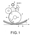
- a stencil printer comprises a printing drum 1 around which a master 2 is wound.
- An ink coater roller 3 is disposed inside the printing drum 1 to rotate about a rotary shaft 4 in the direction of arrow A in contact with the inner peripheral surface of the printing drum 1, thereby supplying ink to the printing drum 1.
- a doctor roller 5 is disposed in the vicinity of the ink coater roller 3 to control the amount of ink supplied to the outer peripheral surface of the ink coater roller 3.
- the doctor roller 5 is provided with respect to the ink coater roller 3 with a space t intervening therebetween.
- An ink fountain 7 is formed at the contact area of the ink coater roller 3 and the doctor roller 5.
- An ink supply mechanism 6 supplies ink to the ink fountain 7 by a ink supply pump (not shown).
- the ink in the ink fountain 7 adheres to the outer peripheral surface of the ink coater roller 3 to form an ink layer 8 of a uniform thickness.
- the ink layer 8 is conveyed to the contact area of the ink coater roller 3 and the printing drum 1 and transferred to the inner peripheral surface of the printing drum 1. Further, the ink transferred to the inner peripheral surface of the printing drum 1 passes through the printing drum 1 under the pressure of the ink coater roller 3 and is transferred to a printing paper 9 through the master 2.
- the amount of ink in the ink fountain 7 is detected by an ink amount detecting device 10 in accordance with a first embodiment of the present invention.
- the ink amount detecting device 10 comprises an oscillator circuit 11, a receiver circuit 12, a detector circuit 13, an amplifier circuit 14, a comparator circuit 15, a detecting circuit 16 and an antenna 17.
- the oscillator circuit 11 is an LC resonance circuit having a winding and a capacitor and the oscillation frequency from the antenna 17 can be controlled by changing the bias of a variable capacitance diode 11A.
- the control signal for changing the bias of the variable capacitance diode 11A is input from the detecting circuit 16.
- the receiver circuit 12 is a kind of tuning circuit and generates a harmonic signal when it receives a signal of a particular frequency and is tuned.
- the electrostatic capacity of the capacitor of the oscillator circuit 11 increases as the amount of ink in the ink fountain 7 increases, and vice versa. Accordingly, in order to keep the amount of ink in the ink fountain 7 constant at a predetermined amount, the bias of the variable capacitance diode 11A of the oscillator circuit 11 is controlled so that a signal of a frequency corresponding to the predetermined amount is oscillated, and the receiver circuit 12 is set to be tuned to the frequency of the oscillator circuit 11.
- the detector circuit 13 converts the frequency signal generated by the receiver circuit 12 to a DC voltage.
- the amplifier circuit 14 amplifies the DC voltage output from the detector circuit 13.
- the comparator circuit 15 compares the value of the signal output from the amplifier circuit 14 with a reference value. When the value of the signal output from the amplifier circuit 14 is not smaller than the reference value, the comparator circuit 15 generates an ON-signal to turn on a switching circuit 20. Whereas when the value of the signal output from the amplifier circuit 14 is smaller than the reference value, the comparator circuit 15 generates an OFF-signal to turn off the switching circuit 20.
- the switching circuit 20 is for controlling the ink supply pump (not shown) and only when the switching circuit 20 is on, the ink supply pump supplies ink to the ink fountain 7.
- the detecting circuit 16 reads out information representing the kind of ink stored in a memory 32 attached to the ink bottle 31, and generates a control signal for setting the bias of the variable capacitance diode 11A of the oscillator circuit 11 with reference to a table 16B ( Figure 2) representing the relation between the kind of the ink and the bias of the variable capacitance diode 11A (based on the dielectric constant according to the kind of ink) .
- Bias of the variable capacitance diode 11A to cause the oscillator circuit 11 to oscillate at a frequency optimal to the dielectric constant of the ink is calculated in advance for each of a plurality of kinds of ink and the kind of ink is related to the calculated bias in the table 16B.
- the detecting circuit 16 is provided with a connector 16A which is connected to a circuit board 33 on which the memory 33 is mounted and reads out the kind of the ink stored in the memory 32.
- a connector 16A which is connected to a circuit board 33 on which the memory 33 is mounted and reads out the kind of the ink stored in the memory 32.
- the detecting circuit 16 is also connected to a display panel 41 and determination in processing performed by the detecting circuit 16 is displayed on the display panel 41.
- FIG. 4 shows the processing to be performed by the detecting circuit 16.
- the detecting circuit first determines whether an ink bottle 31 has been set in the stencil printer. (steps S11 and S12) When it is determined in step S12 that an ink bottle 31 has been set in the stencil printer, the detecting circuit 16 reads out ink information representing the kind of the ink in the ink bottle 31 from a memory 32 attached to the ink bottle 31. (step S14) When it is determined in step S12 that an ink bottle 31 has not been set in the stencil printer, a display to call upon the operator to set an ink bottle 31 is made on the display panel 41. (step S13) Steps S11 to S13 are repeated until an ink bottle 31 is set.
- the detecting circuit 16 After reading out the ink information, the detecting circuit 16 refers to the table 16B and determines whether the kind of the ink read out is in the table 16B. (step S15) When it is determined in step S15 that the kind of the ink read out is in the table 16B, the detecting circuit 16 gets bias of the variable capacitance diode 11A corresponding to the kind of the ink from the table 16B (step S16), and outputs a control signal corresponding to the bias to the oscillator circuit 11 (step S17).
- step S15 whereby it is determined in step S15 that the kind of the ink read out is not in the table 16B, an error message such as "The kind of ink is not good" is displayed on the display panel 41 (step S18) and the bias is set to a default value (step S19). Thereafter, the detecting circuit 16 proceeds to step S17. Then the oscillator circuit 11 sets the oscillation frequency according to the bias represented by the control signal. (step S20)
- the oscillator circuit 11 oscillates at an oscillation frequency thus set.
- the dielectric constant of the ink increases the electrostatic capacity and the oscillation frequency at which the oscillator circuit 11 actually oscillates becomes lower than the oscillation frequency set by the control signal from the detecting circuit 16.
- the receiver circuit 12 since the receiver circuit 12 is not tuned to the oscillation frequency of the oscillator circuit 11, the output voltage from the receiver circuit 12 becomes lower than when the receiver circuit 12 is tuned to the oscillation frequency of the oscillator circuit 11. Accordingly, the value of the signal output from the amplifier circuit 14 is smaller than the reference value and the comparator circuit 15 generates an off signal, whereby the switching circuit 20 is turned off. In this state, the ink supply pump is not operated and no ink is supplied to the ink fountain 7.
- the oscillator circuit 11 oscillates at the oscillation frequency set by the control signal from the detecting circuit 16.
- the receiver circuit 12 is tuned to the oscillation frequency of the oscillator circuit 11 and outputs a harmonic signal at a high voltage. Accordingly, the value of the signal output from the amplifier circuit 14 is not smaller than the reference value and the comparator circuit 15 generates an on signal, whereby the switching circuit 20 is turned on. In this state, the ink supply pump is operated and ink is supplied to the ink fountain 7 from the ink bottle 31.
- the change of the oscillation frequency of the oscillator circuit 11 is changed according to the kind of the ink or the dielectric constant of the ink, the change of the oscillation frequency can be easily detected by increasing the oscillation frequency when the ink is small in dielectric constant and, unnecessary radiation can be suppressed and the accuracy in detecting the change of the oscillation frequency can be improved by decreasing the oscillation frequency when the ink is large in dielectric constant. Accordingly, change of the oscillation frequency can be accurately detected and the amount of ink in the ink fountain can be accurately detected irrespective of the dielectric constant of the ink, which makes it feasible to keep constant the amount of ink in the ink fountain 7 and to obtain high quality images.
- the table 16B represents the relation between the kind of ink and the bias of the variable capacitance diode 11A
- the table 16B may be arranged to represent the relation between the dielectric constant of ink and the bias of the variable capacitance diode 11A when the ink information stored in the memory 32 represents the dielectric constant of the ink.
- the ink information stored in the memory 32 represents another factor such as the viscosity of the ink, the color of the ink, the time for which the ink is left to stand or the date of production of the ink which can affect the dielectric constant of the ink
- the table 16B may be arranged to represent the relation between such a factor and the bias of the variable capacitance diode 11A.
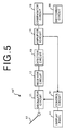
- FIG. 5 is a block diagram showing the structure of an ink amount detecting device 10' in accordance with a second embodiment of the present invention.
- the ink amount detecting device 10' of this embodiment differs from the ink amount detecting device 10 of the first embodiment in that a control circuit 51 which measures the dielectric constant of the ink and outputs a control signal for changing the oscillation frequency of the oscillator circuit 11 according to the measured dielectric constant of the ink is provided in place of the detecting circuit 16.
- the control circuit 51 outputs a control signal which sets the bias of the variable capacitance diode 11A of the oscillator circuit 11 so that the value of the signal output from the amplifier circuit 14 becomes equal to a reference value and the oscillator circuit 11 oscillates at the frequency at which the value of the signal output from the amplifier circuit 14 becomes equal to the reference value. Since the output signal of the amplifier circuit 14 is an analog signal, the control circuit 51 is provided with an A/D convertor.
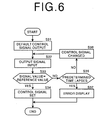
- the depth to which the antenna 17 is dipped in the ink fountain 7 is set to a predetermined default value.
- a control signal for setting the bias of the variable capacitance diode 11A of the oscillator circuit 11 to an initial value is first output to the oscillator circuit 11.
- step S31 This causes the oscillator circuit 11 to oscillate at the default oscillation frequency, whereby the receiver circuit 12 outputs an output signal and the amplifier circuit 14 amplifies the output signal and inputs the amplified output signal into the control circuit 51.
- step S32 Then whether the output signal is equal to the reference value is determined.
- step S33 When it is determined in step S33 that the output signal is equal to the reference value, the control signal is set to provide the bias at that time. (step S34) Otherwise, the control signal is changed to change the bias of the variable capacitance diode 11A of the oscillator circuit 11 (step S36) and then step S32 and S33 are repeated until the output signal becomes equal to the reference value. Steps S36, S32 and S33 are repeated until the output signal becomes equal to the reference value in a predetermined time interval. When the output signal does not become equal to the reference value in the predetermined time interval, an error message to the effect that it is impossible to detect the amount of ink is displayed on the display panel 41 (step S37).
- the oscillation frequency of the oscillator circuit 11 is changed by setting the bias of the variable capacitance diode 11A of the oscillator circuit 11 by the detecting circuit 16 in the first embodiment and by the control circuit 51 in the second embodiment, the oscillation frequency may be changed by manually inputting a desired oscillation frequency through a keyboard or a control panel.
Landscapes
- Inking, Control Or Cleaning Of Printing Machines (AREA)
- Measurement Of Levels Of Liquids Or Fluent Solid Materials (AREA)
- Particle Formation And Scattering Control In Inkjet Printers (AREA)
Abstract
Description
- This invention relates to a method of and a device for detecting the amount of ink in the ink fountain in a printer such as a stencil printer, and more particularly to such a method and a device in which the amount of ink is detected on the basis of the oscillation frequency.
- There has been known a printer such as a stencil printer in which ink is supplied to an ink fountain in a printing drum by an ink pump from an exchangeable ink container. In such a printer, the amount of ink in the ink fountain is detected by an ink sensor and when the ink in the ink fountain is consumed to a predetermined amount, the ink pump is operated to replenish the ink fountain with the ink from the ink container in order to keep constant the amount of ink in the ink fountain. (See, for instance, Japanese Unexamined Patent Publication No. 60(1985)-193687)
- As a method of detecting the amount of ink, there has been proposed a method in which the tip of a needle antenna connected to an oscillator is dipped in the ink and the amount of the ink is detected on the basis of the oscillation frequency of the oscillator which varies with the depth to which the antenna is dipped in the ink. (See, for instance, Japanese Unexamined Patent Publication No. 58 (1983) -62520) With this method, since as the depth to which the antenna is dipped in the ink increases, the electrostatic capacity around the antenna increases and the oscillation frequency of the oscillator lowers, the amount of ink in the ink fountain can be kept constant by replenishing the ink fountain with the ink so that the oscillation frequency detected becomes constant.
- However, the oscillation frequency also depends upon the dielectric constant of the ink, and when the ink is small in dielectric constant, change of the oscillation frequency is small, which makes it difficult to detect change of the oscillation frequency with change of the amount of ink in the ink fountain. To the contrast, when the ink is large in dielectric constant, unnecessary radiation increases and the accuracy in detecting the change of the oscillation frequency is deteriorated. When detection of change of the oscillation frequency with change of the amount of ink in the ink fountain is difficult or the accuracy in detecting the change of the oscillation frequency is deteriorated, it becomes impossible to keep constant the amount of ink in the ink fountain and as a result, quality of the printed image deteriorates.
- In view of the foregoing observations and description, the primary object of the present invention is to provide a method of and a device for detecting the amount of ink which can properly detect change of the oscillation frequency irrespective of the dielectric constant of the ink.
- In accordance with a first aspect of the present invention, there is provided a method of detecting the amount of ink in an ink fountain in a printer on the basis of change of oscillation frequency wherein the improvement comprises
the step of changing the oscillation frequency on the basis of dielectric constant information on the dielectric constant of the ink. - The dielectric constant information may represent the dielectric constant of the ink itself, or may represent other factors such as the viscosity of the ink, the color of the ink, the time for which the ink is left to stand and the date of production of the ink on the basis of which the dielectric constant of the ink can be calculated.
- The dielectric constant information may be obtained by measuring the dielectric constant of the ink or may be obtained from an information storage means attached to the ink bottle for supplying ink to the ink fountain.
- As the information storage means, for instance, a nonvolatile memory (e.g., an EEPROM) which can hold data for a predetermined time interval without supplying power. This applicant has proposed a system for variously controlling a printer on the basis of information stored in such an information storage means attached to consumables like an ink bottle. See Japanese Unexamined Patent Publication No. 2001-18507.
- Further the dielectric constant information may be input through an input means.
- In accordance with a second aspect of the present invention, there is provided a device for detecting the amount of ink in an ink fountain in a printer on the basis of change of oscillation frequency wherein the improvement comprises
a frequency changing means which changes the oscillation frequency on the basis of dielectric constant information on the dielectric constant of the ink. - The frequency changing means may be arranged to obtain the dielectric constant information by measuring the dielectric constant of the ink and to change the oscillation frequency on the basis of the dielectric constant information thus obtained.
- Further, the frequency changing means may be arranged to change the oscillation frequency on the basis of dielectric constant information provided from an information storage means attached to the ink bottle for supplying ink to the ink fountain.
- The device may further comprises an input means so that the frequency changing means changes the oscillation frequency on the basis of the dielectric constant information input through the input means.
- In accordance with the present invention, since the oscillation frequency is changed on the basis of the dielectric constant information, the change of the oscillation frequency can be easily detected by increasing the oscillation frequency when the ink is small in dielectric constant and, unnecessary radiation can be suppressed and the accuracy in detecting the change of the oscillation frequency can be improved by decreasing the oscillation frequency when the ink is large in dielectric constant, whereby change of the oscillation frequency can be accurately detected and the amount of ink in the ink fountain can be accurately detected irrespective of the dielectric constant of the ink, which makes it feasible to keep constant the amount of ink in the ink fountain and to obtain high quality images.
-
- Figure 1 is a schematic view showing an important part of a stencil printer employing an ink amount detecting device for detecting the amount of ink in accordance with a first embodiment of the present invention,
- Figure 2 is a block diagram showing the structure of the ink amount detecting device of the first embodiment,
- Figure 3 is a circuit diagram showing a specific circuit of the ink amount detecting device of the first embodiment,
- Figure 4 is a flow chart for illustrating operation of the ink amount detecting device of the first embodiment,
- Figure 5 is a block diagram showing the structure of an ink amount detecting device in accordance with a second embodiment of the present invention, and
- Figure 6 is a flow chart for illustrating operation of the ink amount detecting device of the second embodiment.
-
- In Figure 1, a stencil printer comprises a printing drum 1 around which a
master 2 is wound. Anink coater roller 3 is disposed inside the printing drum 1 to rotate about a rotary shaft 4 in the direction of arrow A in contact with the inner peripheral surface of the printing drum 1, thereby supplying ink to the printing drum 1. Adoctor roller 5 is disposed in the vicinity of theink coater roller 3 to control the amount of ink supplied to the outer peripheral surface of theink coater roller 3. Thedoctor roller 5 is provided with respect to theink coater roller 3 with a space t intervening therebetween. An ink fountain 7 is formed at the contact area of theink coater roller 3 and thedoctor roller 5. Anink supply mechanism 6 supplies ink to the ink fountain 7 by a ink supply pump (not shown). - When passing through the space t between the
ink coater roller 3 and thedoctor roller 5 in response to rotation of theink coater roller 3, the ink in the ink fountain 7 adheres to the outer peripheral surface of theink coater roller 3 to form anink layer 8 of a uniform thickness. As theink coater roller 3 rotates, theink layer 8 is conveyed to the contact area of theink coater roller 3 and the printing drum 1 and transferred to the inner peripheral surface of the printing drum 1. Further, the ink transferred to the inner peripheral surface of the printing drum 1 passes through the printing drum 1 under the pressure of theink coater roller 3 and is transferred to aprinting paper 9 through themaster 2. - The amount of ink in the ink fountain 7 is detected by an ink
amount detecting device 10 in accordance with a first embodiment of the present invention. As shown in Figure 2, the inkamount detecting device 10 comprises anoscillator circuit 11, areceiver circuit 12, adetector circuit 13, anamplifier circuit 14, acomparator circuit 15, a detectingcircuit 16 and anantenna 17. - With reference to also Figure 3, the
oscillator circuit 11 is an LC resonance circuit having a winding and a capacitor and the oscillation frequency from theantenna 17 can be controlled by changing the bias of avariable capacitance diode 11A. The control signal for changing the bias of thevariable capacitance diode 11A is input from the detectingcircuit 16. - The
receiver circuit 12 is a kind of tuning circuit and generates a harmonic signal when it receives a signal of a particular frequency and is tuned. - Since ink is larger than air in dielectric constant, the electrostatic capacity of the capacitor of the
oscillator circuit 11 increases as the amount of ink in the ink fountain 7 increases, and vice versa. Accordingly, in order to keep the amount of ink in the ink fountain 7 constant at a predetermined amount, the bias of thevariable capacitance diode 11A of theoscillator circuit 11 is controlled so that a signal of a frequency corresponding to the predetermined amount is oscillated, and thereceiver circuit 12 is set to be tuned to the frequency of theoscillator circuit 11. - The
detector circuit 13 converts the frequency signal generated by thereceiver circuit 12 to a DC voltage. - The
amplifier circuit 14 amplifies the DC voltage output from thedetector circuit 13. - The
comparator circuit 15 compares the value of the signal output from theamplifier circuit 14 with a reference value. When the value of the signal output from theamplifier circuit 14 is not smaller than the reference value, thecomparator circuit 15 generates an ON-signal to turn on aswitching circuit 20. Whereas when the value of the signal output from theamplifier circuit 14 is smaller than the reference value, thecomparator circuit 15 generates an OFF-signal to turn off theswitching circuit 20. Theswitching circuit 20 is for controlling the ink supply pump (not shown) and only when theswitching circuit 20 is on, the ink supply pump supplies ink to the ink fountain 7. - The detecting
circuit 16 reads out information representing the kind of ink stored in amemory 32 attached to theink bottle 31, and generates a control signal for setting the bias of thevariable capacitance diode 11A of theoscillator circuit 11 with reference to a table 16B (Figure 2) representing the relation between the kind of the ink and the bias of thevariable capacitance diode 11A (based on the dielectric constant according to the kind of ink) . Bias of thevariable capacitance diode 11A to cause theoscillator circuit 11 to oscillate at a frequency optimal to the dielectric constant of the ink is calculated in advance for each of a plurality of kinds of ink and the kind of ink is related to the calculated bias in the table 16B. - The detecting
circuit 16 is provided with aconnector 16A which is connected to acircuit board 33 on which thememory 33 is mounted and reads out the kind of the ink stored in thememory 32. When theink bottle 31 is set in the stencil printer and thecircuit board 33 is connected to theconnector 16A, the kind of the ink stored in thememory 32 is read out. The detectingcircuit 16 is also connected to adisplay panel 41 and determination in processing performed by the detectingcircuit 16 is displayed on thedisplay panel 41. - Operation of the stencil printer will be described, hereinbelow. Figure 4 shows the processing to be performed by the detecting
circuit 16. The detecting circuit first determines whether anink bottle 31 has been set in the stencil printer. (steps S11 and S12) When it is determined in step S12 that anink bottle 31 has been set in the stencil printer, the detectingcircuit 16 reads out ink information representing the kind of the ink in theink bottle 31 from amemory 32 attached to theink bottle 31. (step S14) When it is determined in step S12 that anink bottle 31 has not been set in the stencil printer, a display to call upon the operator to set anink bottle 31 is made on thedisplay panel 41. (step S13) Steps S11 to S13 are repeated until anink bottle 31 is set. - After reading out the ink information, the detecting
circuit 16 refers to the table 16B and determines whether the kind of the ink read out is in the table 16B. (step S15) When it is determined in step S15 that the kind of the ink read out is in the table 16B, the detectingcircuit 16 gets bias of thevariable capacitance diode 11A corresponding to the kind of the ink from the table 16B (step S16), and outputs a control signal corresponding to the bias to the oscillator circuit 11 (step S17). Whereas when it is determined in step S15 that the kind of the ink read out is not in the table 16B, an error message such as "The kind of ink is not good" is displayed on the display panel 41 (step S18) and the bias is set to a default value (step S19). Thereafter, the detectingcircuit 16 proceeds to step S17. Then theoscillator circuit 11 sets the oscillation frequency according to the bias represented by the control signal. (step S20) - The
oscillator circuit 11 oscillates at an oscillation frequency thus set. When ink exists in the ink fountain 7 and the tip of theantenna 17 is in contact with the ink, the dielectric constant of the ink increases the electrostatic capacity and the oscillation frequency at which theoscillator circuit 11 actually oscillates becomes lower than the oscillation frequency set by the control signal from the detectingcircuit 16. At this time, since thereceiver circuit 12 is not tuned to the oscillation frequency of theoscillator circuit 11, the output voltage from thereceiver circuit 12 becomes lower than when thereceiver circuit 12 is tuned to the oscillation frequency of theoscillator circuit 11. Accordingly, the value of the signal output from theamplifier circuit 14 is smaller than the reference value and thecomparator circuit 15 generates an off signal, whereby the switchingcircuit 20 is turned off. In this state, the ink supply pump is not operated and no ink is supplied to the ink fountain 7. - To the contrast, when the ink in the ink fountain 7 is consumed and the tip of the
antenna 17 comes to be away from the ink, theoscillator circuit 11 oscillates at the oscillation frequency set by the control signal from the detectingcircuit 16. At this time, thereceiver circuit 12 is tuned to the oscillation frequency of theoscillator circuit 11 and outputs a harmonic signal at a high voltage. Accordingly, the value of the signal output from theamplifier circuit 14 is not smaller than the reference value and thecomparator circuit 15 generates an on signal, whereby the switchingcircuit 20 is turned on. In this state, the ink supply pump is operated and ink is supplied to the ink fountain 7 from theink bottle 31. - Then, when the amount of ink in the fountain 7 is increased and the
antenna 17 is brought into contact with the ink again, the ink pump is stopped, whereby the amount of ink in the ink fountain 7 is kept constant during printing. - In the stencil printer, since the oscillation frequency of the
oscillator circuit 11 is changed according to the kind of the ink or the dielectric constant of the ink, the change of the oscillation frequency can be easily detected by increasing the oscillation frequency when the ink is small in dielectric constant and, unnecessary radiation can be suppressed and the accuracy in detecting the change of the oscillation frequency can be improved by decreasing the oscillation frequency when the ink is large in dielectric constant. Accordingly, change of the oscillation frequency can be accurately detected and the amount of ink in the ink fountain can be accurately detected irrespective of the dielectric constant of the ink, which makes it feasible to keep constant the amount of ink in the ink fountain 7 and to obtain high quality images. - Though, in the first embodiment described above, the table 16B represents the relation between the kind of ink and the bias of the
variable capacitance diode 11A, the table 16B may be arranged to represent the relation between the dielectric constant of ink and the bias of thevariable capacitance diode 11A when the ink information stored in thememory 32 represents the dielectric constant of the ink. Further, when the ink information stored in thememory 32 represents another factor such as the viscosity of the ink, the color of the ink, the time for which the ink is left to stand or the date of production of the ink which can affect the dielectric constant of the ink, the table 16B may be arranged to represent the relation between such a factor and the bias of thevariable capacitance diode 11A. - Figure 5 is a block diagram showing the structure of an ink amount detecting device 10' in accordance with a second embodiment of the present invention. The ink amount detecting device 10' of this embodiment differs from the ink
amount detecting device 10 of the first embodiment in that acontrol circuit 51 which measures the dielectric constant of the ink and outputs a control signal for changing the oscillation frequency of theoscillator circuit 11 according to the measured dielectric constant of the ink is provided in place of the detectingcircuit 16. - The
control circuit 51 outputs a control signal which sets the bias of thevariable capacitance diode 11A of theoscillator circuit 11 so that the value of the signal output from theamplifier circuit 14 becomes equal to a reference value and theoscillator circuit 11 oscillates at the frequency at which the value of the signal output from theamplifier circuit 14 becomes equal to the reference value. Since the output signal of theamplifier circuit 14 is an analog signal, thecontrol circuit 51 is provided with an A/D convertor. - Operation of the second embodiment will be described with reference to the flow chart shown in Figure 6, hereinbelow. In the second embodiment, the depth to which the
antenna 17 is dipped in the ink fountain 7 is set to a predetermined default value. A control signal for setting the bias of thevariable capacitance diode 11A of theoscillator circuit 11 to an initial value is first output to theoscillator circuit 11. (step S31) This causes theoscillator circuit 11 to oscillate at the default oscillation frequency, whereby thereceiver circuit 12 outputs an output signal and theamplifier circuit 14 amplifies the output signal and inputs the amplified output signal into thecontrol circuit 51. (step S32) Then whether the output signal is equal to the reference value is determined. (step S33) When it is determined in step S33 that the output signal is equal to the reference value, the control signal is set to provide the bias at that time. (step S34) Otherwise, the control signal is changed to change the bias of thevariable capacitance diode 11A of the oscillator circuit 11 (step S36) and then step S32 and S33 are repeated until the output signal becomes equal to the reference value. Steps S36, S32 and S33 are repeated until the output signal becomes equal to the reference value in a predetermined time interval. When the output signal does not become equal to the reference value in the predetermined time interval, an error message to the effect that it is impossible to detect the amount of ink is displayed on the display panel 41 (step S37). - Though the oscillation frequency of the
oscillator circuit 11 is changed by setting the bias of thevariable capacitance diode 11A of theoscillator circuit 11 by the detectingcircuit 16 in the first embodiment and by thecontrol circuit 51 in the second embodiment, the oscillation frequency may be changed by manually inputting a desired oscillation frequency through a keyboard or a control panel.
Claims (8)
- A method of detecting the amount of ink in an ink fountain in a printer on the basis of change of oscillation frequency wherein the improvement comprises
the step of changing the oscillation frequency on the basis of dielectric constant information on the dielectric constant of the ink. - A method of detecting the amount of ink in an ink fountain in a printer as defined in Claim 1 in which
the dielectric constant information is obtained by measuring the dielectric constant of the ink. - A method of detecting the amount of ink in an ink fountain in a printer as defined in Claim 1 in which the dielectric constant information is obtained from an information storage means attached to an ink bottle for supplying ink to the ink fountain.
- A method of detecting the amount of ink in an ink fountain in a printer as defined in Claim 1 in which the dielectric constant information is input through an input means .
- In accordance with a second aspect of the present invention, there is provided a device for detecting the amount of ink in an ink fountain in a printer on the basis of change of oscillation frequency wherein the improvement comprises
a frequency changing means which changes the oscillation frequency on the basis of dielectric constant information on the dielectric constant of the ink. - A device for detecting the amount of ink in an ink fountain in a printer as defined in Claim 5 in which the frequency changing means is arranged to obtain the dielectric constant information by measuring the dielectric constant of the ink and to change the oscillation frequency on the basis of the dielectric constant information thus obtained.
- A device for detecting the amount of ink in an ink fountain in a printer as defined in Claim 5 in which the frequency changing means is arranged to change the oscillation frequency on the basis of dielectric constant information provided from an information storage means attached to the ink bottle for supplying ink to the ink fountain.
- A device for detecting the amount of ink in an ink fountain in a printer as defined in Claim 5 further comprising an input means so that the frequency changing means changes the oscillation frequency on the basis of the dielectric constant information input through the input means.
Applications Claiming Priority (2)
| Application Number | Priority Date | Filing Date | Title |
|---|---|---|---|
| JP2001200918A JP3932503B2 (en) | 2001-07-02 | 2001-07-02 | Ink amount detection method and apparatus |
| JP2001200918 | 2001-07-02 |
Publications (3)
| Publication Number | Publication Date |
|---|---|
| EP1273442A2 true EP1273442A2 (en) | 2003-01-08 |
| EP1273442A3 EP1273442A3 (en) | 2005-10-12 |
| EP1273442B1 EP1273442B1 (en) | 2007-08-15 |
Family
ID=19037961
Family Applications (1)
| Application Number | Title | Priority Date | Filing Date |
|---|---|---|---|
| EP02014437A Expired - Lifetime EP1273442B1 (en) | 2001-07-02 | 2002-06-28 | Method of and device for detecting amount of ink in ink fountain |
Country Status (5)
| Country | Link |
|---|---|
| US (1) | US6772690B2 (en) |
| EP (1) | EP1273442B1 (en) |
| JP (1) | JP3932503B2 (en) |
| CN (1) | CN1200813C (en) |
| DE (1) | DE60221751T2 (en) |
Cited By (1)
| Publication number | Priority date | Publication date | Assignee | Title |
|---|---|---|---|---|
| EP1916104B2 (en) † | 2006-10-23 | 2020-12-16 | Komori Corporation | Liquid supply apparatus |
Families Citing this family (4)
| Publication number | Priority date | Publication date | Assignee | Title |
|---|---|---|---|---|
| JP2004223950A (en) * | 2003-01-24 | 2004-08-12 | Riso Kagaku Corp | Ink supply method and apparatus, and ink container |
| JP3888458B2 (en) * | 2003-02-27 | 2007-03-07 | 理想科学工業株式会社 | Stencil printing method and apparatus |
| JP4382063B2 (en) | 2006-06-07 | 2009-12-09 | フェリカネットワークス株式会社 | Information processing terminal and reception voltage control method |
| JP4933216B2 (en) * | 2006-10-25 | 2012-05-16 | 東北リコー株式会社 | Stencil printing machine |
Citations (3)
| Publication number | Priority date | Publication date | Assignee | Title |
|---|---|---|---|---|
| JPS5862520A (en) | 1981-10-09 | 1983-04-14 | Riso Kagaku Corp | Detecting device for ink amount |
| JPS60193687A (en) | 1984-03-16 | 1985-10-02 | Riso Kagaku Corp | Detection of remaining ink quantity in ink storage vessel for printer |
| JP2001018507A (en) | 1999-07-07 | 2001-01-23 | Riso Kagaku Corp | Image recording device |
Family Cites Families (6)
| Publication number | Priority date | Publication date | Assignee | Title |
|---|---|---|---|---|
| US3848529A (en) * | 1972-10-24 | 1974-11-19 | Baldwin Gegenheimer Corp | Ink level control system |
| DE3128887C2 (en) * | 1981-07-22 | 1985-10-03 | Baldwin-Gegenheimer GmbH, 8900 Augsburg | Device for supplying a consumer with a medium |
| US5103728A (en) * | 1990-05-29 | 1992-04-14 | Baldwin Technology Corporation | Ink level control system for offset printing presses |
| JPH07186371A (en) * | 1993-12-27 | 1995-07-25 | Riso Kagaku Corp | Motor type ink sensor |
| JP3523941B2 (en) * | 1995-07-28 | 2004-04-26 | 理想科学工業株式会社 | Stencil printing machine |
| US5898308A (en) * | 1997-09-26 | 1999-04-27 | Teleflex Incorporated | Time-based method and device for determining the dielectric constant of a fluid |
-
2001
- 2001-07-02 JP JP2001200918A patent/JP3932503B2/en not_active Expired - Fee Related
-
2002
- 2002-06-28 DE DE60221751T patent/DE60221751T2/en not_active Expired - Lifetime
- 2002-06-28 EP EP02014437A patent/EP1273442B1/en not_active Expired - Lifetime
- 2002-07-01 US US10/184,887 patent/US6772690B2/en not_active Expired - Lifetime
- 2002-07-02 CN CNB021275521A patent/CN1200813C/en not_active Expired - Fee Related
Patent Citations (3)
| Publication number | Priority date | Publication date | Assignee | Title |
|---|---|---|---|---|
| JPS5862520A (en) | 1981-10-09 | 1983-04-14 | Riso Kagaku Corp | Detecting device for ink amount |
| JPS60193687A (en) | 1984-03-16 | 1985-10-02 | Riso Kagaku Corp | Detection of remaining ink quantity in ink storage vessel for printer |
| JP2001018507A (en) | 1999-07-07 | 2001-01-23 | Riso Kagaku Corp | Image recording device |
Cited By (1)
| Publication number | Priority date | Publication date | Assignee | Title |
|---|---|---|---|---|
| EP1916104B2 (en) † | 2006-10-23 | 2020-12-16 | Komori Corporation | Liquid supply apparatus |
Also Published As
| Publication number | Publication date |
|---|---|
| US20030000397A1 (en) | 2003-01-02 |
| DE60221751D1 (en) | 2007-09-27 |
| CN1200813C (en) | 2005-05-11 |
| EP1273442B1 (en) | 2007-08-15 |
| JP3932503B2 (en) | 2007-06-20 |
| CN1394756A (en) | 2003-02-05 |
| EP1273442A3 (en) | 2005-10-12 |
| JP2003011326A (en) | 2003-01-15 |
| DE60221751T2 (en) | 2007-12-27 |
| US6772690B2 (en) | 2004-08-10 |
Similar Documents
| Publication | Publication Date | Title |
|---|---|---|
| JP2000501666A (en) | Consumables management device and method | |
| EP1273442B1 (en) | Method of and device for detecting amount of ink in ink fountain | |
| KR20010007254A (en) | Roll-like printing paper, video printer using such roll-like printing paper and method of detecting remaining quantity of printing paper | |
| US20060150833A1 (en) | Image forming system | |
| US11568190B2 (en) | Liquid surface detector, image forming apparatus, and method for controlling liquid surface detector | |
| JPH0596710A (en) | Ink supply controller for stencil printer | |
| US6448996B2 (en) | Image recording apparatus and method of generating pixel clock | |
| US7430961B2 (en) | Method of and system for forming image and an expendable | |
| US20040141198A1 (en) | Recording apparatus, recording method, recording medium, computer-readable storage medium, and computer system | |
| EP1582345B1 (en) | Method and system for controlling thermal head | |
| EP2408623A1 (en) | Media roll management | |
| KR20030095022A (en) | Toner end detecting method of image forming apparatus | |
| EP0659558A1 (en) | Motor-type ink sensor | |
| EP1586458A1 (en) | Method and system for supplying ink and ink container | |
| EP1074396B1 (en) | Stencil printer | |
| JP2001246827A (en) | Stencil printing apparatus and stencil printing method | |
| US20060102024A1 (en) | Method and system for carrying stencil paper and stencil paper roll | |
| JP3383141B2 (en) | Toner remaining amount detection device | |
| US20060096474A1 (en) | Method of calculating stencil material roll residue, stencil making system and stencil material roll | |
| JP2002046254A (en) | Ink supply stabilization device | |
| JP6463187B2 (en) | Detection device and replacement unit | |
| US20060071958A1 (en) | Pen alignment method and device for printing apparatus | |
| JPH01214755A (en) | Toner concentration control device of image forming apparatus | |
| JP2001150643A (en) | Method and apparatus for stabilizing color tone of printing machine | |
| JPH0852406A (en) | Coating device |
Legal Events
| Date | Code | Title | Description |
|---|---|---|---|
| PUAI | Public reference made under article 153(3) epc to a published international application that has entered the european phase |
Free format text: ORIGINAL CODE: 0009012 |
|
| 17P | Request for examination filed |
Effective date: 20020628 |
|
| AK | Designated contracting states |
Kind code of ref document: A2 Designated state(s): AT BE CH CY DE DK ES FI FR GB GR IE IT LI LU MC NL PT SE TR |
|
| AX | Request for extension of the european patent |
Free format text: AL;LT;LV;MK;RO;SI |
|
| PUAL | Search report despatched |
Free format text: ORIGINAL CODE: 0009013 |
|
| AK | Designated contracting states |
Kind code of ref document: A3 Designated state(s): AT BE CH CY DE DK ES FI FR GB GR IE IT LI LU MC NL PT SE TR |
|
| AX | Request for extension of the european patent |
Extension state: AL LT LV MK RO SI |
|
| GRAP | Despatch of communication of intention to grant a patent |
Free format text: ORIGINAL CODE: EPIDOSNIGR1 |
|
| AKX | Designation fees paid |
Designated state(s): DE FR GB |
|
| GRAS | Grant fee paid |
Free format text: ORIGINAL CODE: EPIDOSNIGR3 |
|
| GRAA | (expected) grant |
Free format text: ORIGINAL CODE: 0009210 |
|
| AK | Designated contracting states |
Kind code of ref document: B1 Designated state(s): DE FR GB |
|
| REG | Reference to a national code |
Ref country code: GB Ref legal event code: FG4D |
|
| REF | Corresponds to: |
Ref document number: 60221751 Country of ref document: DE Date of ref document: 20070927 Kind code of ref document: P |
|
| ET | Fr: translation filed | ||
| PLBE | No opposition filed within time limit |
Free format text: ORIGINAL CODE: 0009261 |
|
| STAA | Information on the status of an ep patent application or granted ep patent |
Free format text: STATUS: NO OPPOSITION FILED WITHIN TIME LIMIT |
|
| 26N | No opposition filed |
Effective date: 20080516 |
|
| REG | Reference to a national code |
Ref country code: FR Ref legal event code: PLFP Year of fee payment: 14 |
|
| PGFP | Annual fee paid to national office [announced via postgrant information from national office to epo] |
Ref country code: DE Payment date: 20150624 Year of fee payment: 14 Ref country code: GB Payment date: 20150624 Year of fee payment: 14 |
|
| PGFP | Annual fee paid to national office [announced via postgrant information from national office to epo] |
Ref country code: FR Payment date: 20150608 Year of fee payment: 14 |
|
| REG | Reference to a national code |
Ref country code: DE Ref legal event code: R119 Ref document number: 60221751 Country of ref document: DE |
|
| GBPC | Gb: european patent ceased through non-payment of renewal fee |
Effective date: 20160628 |
|
| REG | Reference to a national code |
Ref country code: FR Ref legal event code: ST Effective date: 20170228 |
|
| PG25 | Lapsed in a contracting state [announced via postgrant information from national office to epo] |
Ref country code: DE Free format text: LAPSE BECAUSE OF NON-PAYMENT OF DUE FEES Effective date: 20170103 Ref country code: FR Free format text: LAPSE BECAUSE OF NON-PAYMENT OF DUE FEES Effective date: 20160630 |
|
| PG25 | Lapsed in a contracting state [announced via postgrant information from national office to epo] |
Ref country code: GB Free format text: LAPSE BECAUSE OF NON-PAYMENT OF DUE FEES Effective date: 20160628 |