EP1273431A1 - Device and method for top seal packaging - Google Patents
Device and method for top seal packaging Download PDFInfo
- Publication number
- EP1273431A1 EP1273431A1 EP01915789A EP01915789A EP1273431A1 EP 1273431 A1 EP1273431 A1 EP 1273431A1 EP 01915789 A EP01915789 A EP 01915789A EP 01915789 A EP01915789 A EP 01915789A EP 1273431 A1 EP1273431 A1 EP 1273431A1
- Authority
- EP
- European Patent Office
- Prior art keywords
- tray
- stretch film
- film
- stretch
- holding
- Prior art date
- Legal status (The legal status is an assumption and is not a legal conclusion. Google has not performed a legal analysis and makes no representation as to the accuracy of the status listed.)
- Withdrawn
Links
Images











Classifications
-
- B—PERFORMING OPERATIONS; TRANSPORTING
- B31—MAKING ARTICLES OF PAPER, CARDBOARD OR MATERIAL WORKED IN A MANNER ANALOGOUS TO PAPER; WORKING PAPER, CARDBOARD OR MATERIAL WORKED IN A MANNER ANALOGOUS TO PAPER
- B31B—MAKING CONTAINERS OF PAPER, CARDBOARD OR MATERIAL WORKED IN A MANNER ANALOGOUS TO PAPER
- B31B50/00—Making rigid or semi-rigid containers, e.g. boxes or cartons
- B31B50/60—Uniting opposed surfaces or edges; Taping
- B31B50/64—Uniting opposed surfaces or edges; Taping by applying heat or pressure, e.g. by welding
- B31B50/642—Uniting opposed surfaces or edges; Taping by applying heat or pressure, e.g. by welding using sealing jaws or sealing dies
-
- B—PERFORMING OPERATIONS; TRANSPORTING
- B65—CONVEYING; PACKING; STORING; HANDLING THIN OR FILAMENTARY MATERIAL
- B65B—MACHINES, APPARATUS OR DEVICES FOR, OR METHODS OF, PACKAGING ARTICLES OR MATERIALS; UNPACKING
- B65B7/00—Closing containers or receptacles after filling
- B65B7/16—Closing semi-rigid or rigid containers or receptacles not deformed by, or not taking-up shape of, contents, e.g. boxes or cartons
- B65B7/162—Closing semi-rigid or rigid containers or receptacles not deformed by, or not taking-up shape of, contents, e.g. boxes or cartons by feeding web material to securing means
- B65B7/164—Securing by heat-sealing
-
- B—PERFORMING OPERATIONS; TRANSPORTING
- B65—CONVEYING; PACKING; STORING; HANDLING THIN OR FILAMENTARY MATERIAL
- B65B—MACHINES, APPARATUS OR DEVICES FOR, OR METHODS OF, PACKAGING ARTICLES OR MATERIALS; UNPACKING
- B65B11/00—Wrapping, e.g. partially or wholly enclosing, articles or quantities of material, in strips, sheets or blanks, of flexible material
- B65B11/48—Enclosing articles, or quantities of material, by folding a wrapper, e.g. a pocketed wrapper, and securing its opposed free margins to enclose contents
-
- B—PERFORMING OPERATIONS; TRANSPORTING
- B31—MAKING ARTICLES OF PAPER, CARDBOARD OR MATERIAL WORKED IN A MANNER ANALOGOUS TO PAPER; WORKING PAPER, CARDBOARD OR MATERIAL WORKED IN A MANNER ANALOGOUS TO PAPER
- B31B—MAKING CONTAINERS OF PAPER, CARDBOARD OR MATERIAL WORKED IN A MANNER ANALOGOUS TO PAPER
- B31B2105/00—Rigid or semi-rigid containers made by assembling separate sheets, blanks or webs
- B31B2105/002—Making boxes characterised by the shape of the blanks from which they are formed
- B31B2105/0022—Making boxes from tubular webs or blanks, e.g. with separate bottoms, including tube or bottom forming operations
-
- B—PERFORMING OPERATIONS; TRANSPORTING
- B31—MAKING ARTICLES OF PAPER, CARDBOARD OR MATERIAL WORKED IN A MANNER ANALOGOUS TO PAPER; WORKING PAPER, CARDBOARD OR MATERIAL WORKED IN A MANNER ANALOGOUS TO PAPER
- B31B—MAKING CONTAINERS OF PAPER, CARDBOARD OR MATERIAL WORKED IN A MANNER ANALOGOUS TO PAPER
- B31B50/00—Making rigid or semi-rigid containers, e.g. boxes or cartons
- B31B50/60—Uniting opposed surfaces or edges; Taping
Definitions
- the present invention relates to a top-seal wrapping device and a top-seal wrapping method.
- the present invention particularly relates to a top-seal wrapping device for covering an opening of a tray with a stretch film, welding the stretch film to a peripheral portion of the tray opening, and thermally cutting the stretch film.
- the present invention also relates to a top-seal wrapping method for performing such wrapping.
- An over-wrapping method has been widely used for wrapping fresh foods, such as meat and fish, as well as processed foods such as precooked meals.
- a tray is entirely wrapped with a film after arranging the intended contents or a wrapping target therein.
- the tray and contents In the over-wrapping method, however, the tray and contents must be wrapped entirely, and the film portions must be overlapped with each other for sealing. Therefore, the film must have a size that is several times as large as the planar size of the tray. In many cases, the film portions overlap each other on the bottom of the tray, and the bottom surface of the tray is pressed against a heater plate for sealing. Therefore, the sealing ability or reliability is low.
- top-seal method a method, which will be referred to as a top-seal method, has been used instead of the over-wrap method in some cases.
- a film is arranged only over the opening at the top of the trap, and is welded to the peripheral portion of the tray around the opening.
- the required amount of film can be reduced when compared with the over-wrap method.
- top-seal method has been widely employed for wrapping mushrooms such shimeji mushrooms and others. More specifically, the top-seal method is implemented primarily in such a manner that adhesive is applied to a side surface of a tray around an opening, and ends of a film covering the opening are adhered thereto. Alternatively, the top-seal method is implemented in such a manner that a tray and a film having a larger area than the planar area of the tray are held between dies, and are welded together by pressure and heat applied thereto.
- the method of performing the welding with dies can hermetically seal the tray containing contents, i.e., a target to be wrapped, and therefore is superior to the over-wrap method.
- the prior art however, dedicated dies corresponding to tray forms and sizes are employed, and a hard film is used for the wrapping.
- stretch film stretchable film
- stretch film is liable to wrinkle, and when stretch film is placed over the tray the stretch file and contents may exhibit a less desirable appearance than when using the hard film. It is necessary to transport the stretch film, which is thin and does not have sufficient rigidity, to and from a position for welding. Therefore, a large and/or complicated mechanism may be required for the transportation.
- An object of the present invention is to provide a wrapping device and a wrapping method for performing wrapping by welding a stretch film to a tray.
- an object of the present invention is to provide a wrapping device and a wrapping method, which has a good appearance after the wrapping, and can employ a transporting mechanism with a compact structure.
- the present invention provides a top-seal wrapping device for covering a top opening of a tray containing a wrapping target with a stretch film, welding the stretch film to a peripheral portion of the tray around the opening, and thermally cutting the stretch film.
- the top-seal wrapping device includes a stretch mechanism, a control portion, and a film winding portion.
- the stretch mechanism stretches the stretch film.
- the control portion controls the stretching of the stretch film by operating the stretch mechanism at least before welding the stretch film to the tray.
- the film winding portion winds up the stretch film after the thermal cutting.
- the stretch film covers the opening of the tray, is welded to the peripheral portion of the tray around the opening, and is thermally cut.
- a transporting mechanism having a compact structure can be used for transporting a thin stretch film having low rigidity.
- the stretch film is transported by belts holding the opposite sides of the film, or by chains moving in the transporting direction and having clamps for holding the film.
- the wrapping device of this aspect is provided with a film winding portion for ensuring the continuity of the stretch film. Therefore, a stretch film, which is thin and does not have sufficient rigidity, can be transported without holding or pinching it. Accordingly, the transporting mechanism can have a compact structure.
- the stretch mechanism is arranged for stretching the stretch film at least before welding the stretch film to the tray. Therefore, wrinkles of the stretch film covering the opening of the tray are expanded before welding so that the appearance is improved in the wrapped state.
- the top-seal wrapping device of the first aspect further has a feature such that the stretch film is thermally cut at a position outside a portion welded to the peripheral portion around the tray opening.
- the top-seal wrapping device of the first or second aspect further has a feature such that the control portion operates the stretch mechanism to apply a tension to a portion of the stretch film near the cut portion at least after welding the stretch film.
- the tension is applied to the portion near the cut portion after thermally cutting the stretch film. Therefore, the cutting can be completed even when an uncut portion is left. Further, the tension may also be applied to the stretch film during the thermal cutting. This allows easier cutting of the stretch film.
- the top-seal wrapping device of the first, second, or third aspect further includes a film transporting mechanism and a lift mechanism.
- the film transporting mechanism transports the stretch film.
- the lift mechanism lifts the tray to push the stretch film transported by the film transporting mechanism against the tray.
- the control portion operates the stretch mechanism to stretch the stretch film before contact of the tray with the stretch film, and also controls the stretch mechanism to reduce tension of the stretch film after the contact of the tray with the stretch film.
- the lift mechanism pushes the tray against the stretch film to achieve a state in which the stretch film covers the opening of the tray.
- the stretch film is stretched before the tray comes into contact with the stretch film. Therefore, no wrinkles are present in the stretch film when it comes into contact with the tray, and the opening of the tray is covered with the stretch film without a wrinkle.
- the top-seal wrapping device of any one of the preceding aspects further has a feature such that the stretch mechanism is arranged between a supply position of the stretch film and an end of a position of the welding.
- the top-seal wrapping device of any one of the preceding aspects further includes a detecting means.
- the detecting means detects an opening in the stretch film formed by thermal cutting.
- the control portion controls the stretch mechanism not to act on at least a portion of the stretch film including and neighboring the opening detected by the detecting means.
- the opening in the stretch film formed by the thermal cutting is detected.
- the control is performed such that the stretching of the stretch film may not be effected on the portion including and neighboring the detected opening.
- control is performed to stop the stretching of the stretch film having a portion, which was thermally cut and removed. Therefore, meandering and entangling of the stretch film are suppressed even if the strength and rigidity of the film are reduced due to the partial cutting.
- the top-seal wrapping device of any one of the preceding aspects further has a feature such that the stretch mechanism has a plurality of film holding portions for holding the stretch film.
- the plurality of film holding portions holds the stretch film. Therefore, the film holding portion can be arranged at (or moved to) the positions corresponding to the configuration of the tray for appropriately stretching the stretch film in accordance with the tray configuration.
- the top-seal wrapping device of the seventh aspect further has a feature such that the plurality of film holding portions can be set to have different holding forces, respectively.
- the top-seal wrapping device of the seventh or eighth aspect further has a feature such that the control portion changes timing of holding and releasing operations of the plurality of film holding portions based on the properties of at least one of the tray and the stretch film.
- the stretch film can be stretched in accordance with the properties of the tray such as a tray configuration and/or the properties of the stretch film such as a material of the stretch film.
- the top-seal wrapping device of any one of the preceding aspects further has a feature such that the stretch mechanism stretches the stretch film in at least one of either the transporting direction of the stretch film or the width direction perpendicular to said transporting direction.
- the present invention provides a top-seal wrapping method for covering a top opening of a tray containing a wrapping target with a stretch film, welding the stretch film to a peripheral portion of the tray around the opening, and thermally cutting the stretch film.
- the top-seal wrapping method includes a film supply step, a stretch step, and a film winding step.
- the stretch film is transported to a position above the tray.
- the stretch film is stretched in a direction crossing the transporting direction before welding the stretch film to the tray.
- the stretch film is wound after the thermal cutting.
- the top-seal wrapping device of the first aspect further includes a film supply mechanism, a lift mechanism, a heating body, and a tray holding member.
- the film supply mechanism supplies the stretch film to a position above the tray.
- the lift mechanism lifts the tray to push the tray against the stretch film.
- the heating body comes into contact with the peripheral portion of the tray surrounding the opening and contacts the stretch film for welding the stretch film to the peripheral portion of the tray around the opening.
- the tray holding portion holds the tray when welding the stretch film to the peripheral portion of the tray around the opening.
- a conventional top-seal method has been employed for wrapping mushrooms such as shimeji mushrooms and others. More specifically, the top-seal method is implemented primarily in such a manner that adhesive is applied to side surfaces of a tray around an opening. Ends of the film covering the opening are adhered thereto, or in such a manner that the tray and the film having a larger area than the planar area of the tray are held between dies. The tray and the film are welded together by pressure and heat applied thereto.
- the conventional top-seal method described above requires dies corresponding to the forms and sizes of trays. Therefore, the over-wrap method has been widely employed rather than the top-seal method in the fields, which use various types of trays because contents must be arranged in various types of trays having different sizes and/or forms.
- the top-seal method can reduce the required amount of film and can improve the sealing performance, it is necessary in the prior art to prepare dies for each of the trays having different forms and/or sizes. Therefore, the top-seal method has not been employed in some or many cases.
- the assignee has proposed in Japanese Patent Application No. 1999-137025 a device for performing heat sealing (thermal welding) in a manner such that a heating roller is brought into contact with a peripheral portion of a tray around an opening with a film therebetween. The heating roller is pivoted around an axis for welding the film.
- sealing can be effected without a problem if the trays have sizes and forms falling within appropriate ranges.
- different dies are required for different types of trays.
- tooling change is not particularly required if the trays have sizes and forms falling within certain ranges. Thus the sealing operation can continue without a tooling change.
- the assignee has also proposed, in Japanese Patent Application No. 1999-154616, a device for performing heat sealing in a manner such that a tray covered with a stretch film is pushed against a rubber sheet heated by a heater.
- this device it is not necessary to prepare dies dedicated to each of the trays of different forms and sizes, and the sealing operation can continue without tooling change even after a change to a different type of tray.
- the tray receives a force from the heating roller or the rubber sheet in the heat sealing operation.
- This force may shift a planar position of the tray so that large differences may occur in sealing pressure between various portions of a flange of the tray during the heat sealing operation.
- it is desired that the heating roller or the rubber sheet is pushed to various portions of the tray flange with uniform pressure.
- a sealing failure may occur locally if the center of the tray shifts from the pivoting center of the heating roller or the center of the rubber sheet.
- the top-seal wrapping device of the twelfth aspect of the present invention employs a structure for pushing the tray against the stretch film supplied to a position above the tray.
- the heating body is brought into contact with the peripheral portion of the tray surrounding the opening and pushed against the stretch film so that the stretch film is welded to the tray.
- the tray holding member is employed for holding the tray so that the position of the tray may not shift or deviate due to contact with the heating body when welding the stretch film to the tray. Therefore, the tray can maintain an optimum position with respect to the heating body, and the heating body can come into contact with the peripheral portion of the tray around the opening in accordance with the designed manner. This can reduce sealing failures due to positional deviation of the tray.
- Positional deviation of the tray may occur linearly on a plane, angularly on a plane, and/or in a direction of the height.
- the tray holding member is configured in accordance with the characteristics of the device, and can hold the tray to prevent positional deviation in at least one of the above directions.
- the tray holding member may be configured to be in direct contact with the tray for holding the tray, or may be configured to hold indirectly the tray by appropriate means such as suction.
- the top-seal wrapping device of the twelfth aspect further has a feature such that the tray holding member prevents shifting of the position of the tray when the tray is lifted and pushed against the stretch film.
- the tray holding member holds the tray to prevent positional deviation of the tray not only when welding the stretch film to the peripheral portion of the tray around the opening but also when the tray rises and comes into contact with the stretch film. Therefore, it is possible to prevent positional deviation of the tray due to the contact with the stretch film. Thus, sealing failure can be suppressed more effectively.
- the top-seal wrapping device of the twelfth or thirteenth aspect further has a feature such that the tray holding member comes into contact with a side surface of the tray to prevent shifting of the planar position of the tray.
- the top-seal wrapping device of the twelfth, thirteenth, or fourteenth aspect further includes a tray carrying and holding mechanism.
- the tray carrying and holding mechanism is configured to carry the tray thereon and to be transported to the lift mechanism together with the tray.
- the tray holding member is included in the tray carrying and holding mechanism. The lift mechanism lifts the tray by lifting the tray carrying and holding mechanism.
- the tray is placed on the tray carrying and holding mechanism to prevent positional deviation of the tray by the tray holding mechanism. While maintaining this state, the tray is transported to the lift mechanism by transporting the tray carrying and holding mechanism to the lift mechanism. Then, the lift mechanism lifts the tray carrying and holding mechanism to move the tray upward. Therefore, positional deviation of the tray can be prevented during transportation to the lift mechanism as well as lifting by the lift mechanism. Accordingly, the sealing (welding) by the heating body is effected on the tray located in the designed position so that the sealing can be performed more stably.
- the top-seal wrapping device of any one of the twelfth to fifteenth aspects further has a feature such that the tray carrying and holding mechanism is configured to bias the tray holding member toward the tray to adjust the planar position of the tray.
- the tray carrying and holding mechanism serves not only to prevent positional deviation of the tray by the tray holding member but also to adjust the planar position of the tray (e.g., to center the tray).
- the tray holding member is biased toward the tray.
- a spring, an electric motor, a pneumatic cylinder, or a hydraulic cylinder may be used for biasing the tray holding member toward the tray.
- the tray holding member adjusts the position of the tray, and holds the tray while preventing positional deviation of the tray. Thereby, operations such as transfer of the tray from a position adjusting portion to a holding portion are not required, thus, the structure can be simple.
- the top-seal wrapping device of any one of the twelfth to fourteenth aspects further includes position detecting means.
- the position detecting means detects the positional state of the tray during transportation to the lift mechanism.
- the control portion corrects position shift of the tray by the tray holding member based on a result of the detection by the position detecting means.
- the tray holding member corrects positional deviation of the tray, and the tray holding member also holds the tray to prevent positional deviation of the tray.
- the tray holding member is used for correcting positional deviation and preventing subsequent positional deviation, thus, the device can have a simple structure.
- the top-seal wrapping device of any one of the twelfth to fourteenth aspects further includes biasing means.
- the biasing means biases the tray holding member toward the tray.
- the control portion controls a biasing force of the biasing means.
- the tray holding member is biased toward the tray for holding the tray, and thereby prevents positional deviation of the tray.
- the control portion is configured to control the biasing force of the biasing means. Therefore, the force for holding the tray can be changed depending on parameters such as hardness and the material of the tray. For example, the holding force can be controlled to be low for soft trays, and to be high for hard trays. Thereby, it is possible to suppress sealing failure due to deformation of the tray while reliably preventing positional deviation of the tray.
- the top-seal wrapping device of the eighteenth aspect further includes biasing force detecting means.
- the biasing force detecting means detects the biasing force applied by the biasing means.
- the control portion controls the biasing force of the biasing means based on a result of the detection by the biasing force detecting means.
- the biasing means can be controlled while determining the actual biasing force, i.e., actual tray holding force. Therefore, a situation in which an excessively large biasing force collapses a soft tray does not occur. Further, the tray can be held with a holding force that corresponds to the properties of the tray.
- the wrapping device of the eighteenth aspect further has a feature such that the control portion controls the biasing force of the biasing means corresponding to the properties of at least the tray and/or the stretch film.
- the biasing force of the biasing means, and thus the holding force for the tray can be adjusted in accordance with the properties of the tray such as hardness and material of the tray, and/or the properties of the stretch film such as thickness and material of the stretch film.
- the top-seal wrapping device of the first aspect further includes a film supply mechanism, a lift mechanism, a heating body, and a position adjusting mechanism.
- the film supply mechanism supplies the stretch film to a position above the tray.
- the lift mechanism lifts and pushes the tray against the stretch film.
- the heating body comes into contact with the peripheral portion of the tray surrounding the opening and being in contact with the stretch film.
- the heating body welds the stretch film to a peripheral portion of the tray around the opening.
- the position adjusting mechanism adjusts the planar position of the tray before the tray comes into contact with the stretch film.
- the tray is pushed against the stretch film supplied to a position above the tray. Additionally, the heating body is brought into contact with the peripheral portion of the tray, which is located around the opening and is in contact with the stretch film, for welding the stretch film to the tray. Further, the tray is located at an optimum position for the heating body when welding the tray to the stretch film, and for this purpose, the position adjusting mechanism is employed for adjusting the planar position of the tray before pushing the tray against the stretch film. Therefore, the tray located at the adjusted optimum position comes into contact with the stretch film, and is welded by the heating body to the stretch film. In this structure, as described above, the position of the tray with respect to the heating body is adjusted to be optimal so that sealing failures due to positional deviation of the tray can be suppressed.
- the top-seal wrapping method of the eleventh aspect further includes a position adjusting step, a lift step, and a welding step.
- the position adjusting step is executed by adjusting the planar position of the tray.
- the lift step is executed by lifting and pushing the tray against the stretch film.
- the welding step is executed by bringing a heating body into contact with the peripheral portion of the tray located around the opening and being in contact with the stretch film, and thereby welding the stretch film to the peripheral portion of the tray around the opening.
- Figs. 1 and 2 show a top-seal type wrapping device according to an embodiment of the present invention.
- the wrapping device 1 shown in Figs. 1 and 2 is used for covering a top opening o (Fig. 7) of a tray T, in which a fresh food such as meat and fish as well as a processed food such as a precooked meal are arranged, with a stretch film Fm.
- the wrapping device 1 is also used for welding the stretch film Fm to a flange (a peripheral portion around the opening) f (Fig. 7) of the tray T located around the opening o for sealing the wrapped tray.
- the wrapping device 1 includes a frame 1a, a tray carrying and holding mechanism 2, four rollers 3, a film transporting mechanism 5, a lift mechanism 6, a roller elevating mechanism 7, a roller pivot mechanism 8, a stretch mechanism 9, and a control portion 10 (Fig. 9).
- the tray carrying and holding mechanism 2 holds the tray T.
- the four rollers (heating bodies) 3 are arranged above the tray carrying and holding mechanism 2.
- the film transporting mechanism 5 supplies the stretch film Fm to a position between the tray carrying and holding mechanism 2 and the rollers 3.
- the lift mechanism 6 vertically moves the tray carrying and holding mechanism 2.
- the roller elevating mechanism 7 moves the rollers 3 primarily in a vertical direction.
- the roller pivot mechanism 8 has two pivot shafts 81a and 81b for pivoting the rollers 3 around each of the pivot shafts 81a and 81b.
- the stretch mechanism 9 stretches the stretch film Fm between the tray carrying and holding mechanism 2 and the rollers 3.
- the control portion 10 controls the respective mechanisms.
- the tray carrying and holding mechanism 2 is employed for carrying and holding the tray T thereon, and is moved vertically by the lift mechanism 6.
- the tray carrying and holding mechanism 2 can be pulled out from a position depicted by a solid line in Fig. 2 to a position depicted by a line with alternating long and two short dashes, and can be pushed in reversely. This horizontal movement is performed manually or by drive means (not shown).
- the operation of placing the tray T on the tray carrying and holding mechanism 2 may be performed manually by an operator, or may be automatically performed by a tray transporting device (not shown) or the like.
- Each roller 3 is a cylindrical member, and is rotatably supported by a roller support 71 of the roller elevating mechanism 7, which will be described later.
- the roller 3 is provided at its surface with a layer softer than the other portions for reducing frictional resistance with respect to the stretch film Fm. More specifically, the surface of the roller 3 is made of an elastic material such as resin or synthetic rubber so that the stretch film Fm can be closely pressed against the flange f even when fine irregularities are present on the surface of the flange f of the tray T.
- Fig. 5 shows an arrangement of the rollers 3 viewed from the lower side. In a plan view, the rollers 3 are arranged as shown in Fig. 5, and the two rollers 3 attached to each of the pivot shafts 81a and 81b form an angle of about 110 degrees.
- each roller 3 supported by the roller supports 71 are inclined with respect to the horizontal top surface of the tray T. Owing to this inclination, the end of each roller 3 near the pivot shaft 81a or 81b is located at a higher level than its opposing end.
- the roller 3 is internally provided with a heater 31 (Fig. 9) for heating the roller 3. Specifications of this heater are appropriately selected in accordance with the materials of the tray T and the stretch film Fm and in view of the fact that an energy must be supplied for restoring the heat quantity, which is lost in the sealing operation, within a short time.
- the film transporting mechanism 5 is employed for paying out the stretch film Fm to a position between the tray carrying and holding mechanism 2 in the lowered position and the rollers 3.
- the film transporting mechanism 5 is also employed for winding up the stretch film Fm, which is partially and thermally cut out for the sealing operation.
- the film transporting mechanism 5 is formed of, as shown in Fig. 1, a film set portion 51, a film winding portion 53, and a film transporting portion 52.
- the film set portion 51, the film transporting portion 52, and the film winding portion 53 are provided on the frame 1a.
- the film set portion 51 is formed of members for rotatably supporting a film roll R of the stretch film Fm, and holds the film roll R to form the source of the stretch film Fm.
- the film set portion 51 has a vertically movable core support member 51a and a support roller 51b supporting a lower side of the film roll R in an obliquely upward direction.
- the film roll R is supported by the core support member 51a and the support roller 51b as well as a payoff roller 52a of the film transporting portion 52, which will be described later (see Fig. 1).
- the film winding portion 53 is provided for winding up the remaining stretch film Fm, which is partially cut out for wrapping the tray T in the top-seal manner, and has a winding shaft 53a.
- the winding shaft 53a is driven via a belt 53b by an electric motor 52C, which will be described later.
- the specific structure of the winding shaft 53a will be described later.
- the film transporting portion 52 includes the payoff roller 52a, a motor 52c for driving the payoff roller 52a via a belt 52b, and a film support roller 52d.
- the stretch film Fm pulled out from the film roll R is sent toward the film winding portion 53 by the payoff roller 52a. Since the motor 52c drives not only the payoff roller 52a but also the winding shaft 53a, the stretch film Fm is payed out from the film roll R, and is wound around the winding shaft 53a.
- the rotation speed of the winding shaft 53a is higher than the rotation speed of the payoff roller 52a. Therefore, the stretch film Fm is subjected to a tension in the transporting direction. Thereby, the film can be transported without slack.
- the payoff roller 52a has a grip with respect to the stretch film Fm, and can pay out the stretch film Fm to a predetermined amount without slip. More specifically, the payoff roller 52a has a mirror-finished surface. A one-way clutch (not shown) for preventing reverse rotation of the payoff roller 52a is arranged.
- the payoff roller 52a and the support roller 51b are arranged symmetrically with respect to the core support member 51a, as shown in Fig. 1.
- a distance between the payoff roller 52a and the support roller 51b is smaller than a diameter of the core member of the film roll R so that the film roll R may not fall through a space between the rollers 52a and 51b.
- the film support roller 52d is arranged near the film winding portion 53, and has a top surface at the same level as the lowest surface of the payoff roller 52a (see Fig. 1). Therefore, a portion of the stretch film Fm, which is being transported between the payoff roller 52a and the film support roller 52d, is kept horizontal.
- the stretch mechanism 9 holds the stretch film Fm extending from the film set portion 51 to the film winding portion 53. More specifically, the stretch mechanism 9 holds the opposite sides or edges of the horizontal portion of the stretch film Fm located between the payoff roller 52a and the film support roller 52d for stretching widthwise (i.e., laterally in Fig. 2) the stretch film Fm.
- This stretch mechanism 9 has a pair of film holding portions 91a and 91b extending in the film transporting direction, and a stretch drive portion 93 (see Fig. 9) for moving the film holding portions 91a and 91b in a direction (i.e., laterally in Fig. 2) perpendicular to the film transporting direction.
- the film holding portions 91a and 91b are configured to pinch and hold vertically opposite sides of the stretch film Fm, and are turned on/off by solenoids 92a and 92b (see Fig. 9), respectively.
- the stretch drive portion 93 is formed of an electric motor 93a (see Fig. 9), guide rails, sprockets, chains, and others.
- the stretch drive portion 93 moves the film holding portions 91a and 91b laterally in Fig. 2 in accordance with an instruction sent from the control portion 10.
- the lift mechanism 6 is provided for pushing up the tray carrying and holding mechanism 2 that holds the tray T against the stretch film Fm, as shown in Fig. 3.
- the lift mechanism 6 is formed of a drive motor 61, a large gear 62 carried on the frame 1a, a link member 63, a lever 64 having one end pivotably attached to a fulcrum 64a on the frame 1a, a circular plate 65 rotatably attached to the other end of the lever 64, and others.
- the drive motor 61 When the drive motor 61 operates, it rotates the large gear 62 via a gear fixed to the motor shaft. Thereby, the link member 63 moves the level 64 to pivot around the fulcrum 64a. Thereby, the tray carrying and holding mechanism 2 having the lower surface, which is supported by the circular member 65, moves upward or downward (see Figs. 2 and 3).
- the tray carrying and holding mechanism 2 is guided by vertical guide rails 69 so that it moves in the vertical direction in accordance with the operation of the lift mechanism 6.
- the roller elevating mechanism 7 is employed for changing the vertical position of the rollers 3.
- the roller elevating mechanism 7 is formed of, as shown in Fig. 1, roller supports 71, link mechanisms 72, a pushing plate 73, a lever mechanism 74, and an electric motor 75.
- the lever mechanism 74 applies a downward force to the pushing plate 73.
- the electric motor 75 operates the lever mechanism 74.
- the roller support 71 supports the axes of the rollers 3, which are inclined in the side view as shown in Figs. 1 and 2.
- a rotation axis of the roller 3 is depicted by alternate long and short dash lines in Figs. 1 and 2.
- the link mechanism 72 has an end supporting the roller support portion 71 via a pin, and has another end that can be pushed down by the pushing plate 73.
- the end of the link mechanism 72 remote from the pushed end occupies a raised position so that the roller support 71 and the rollers 3 occupy raised positions, respectively.
- the pushing plate 73 does not apply force to the link mechanisms 72, the other end of the link mechanism 72 lowers, e.g., owing to the weights of the roller supports 71 and the rollers 3 (see Figs. 2 and 4).
- the pushing plate 73 receives a downward force from the lever mechanism 74 operated by the motor 75. As shown in Figs. 2 and 4, the outer peripheral portion of the pushing plate 73 is placed on rollers each supported by the other end of the link mechanism 72.
- the roller pivot mechanism 8 (Fig. 1 and 2) is provided for pivoting the roller 3 as well as the roller supports 71 and the link mechanisms 72 through a predetermined angle when performing the wrapping.
- This roller pivot mechanism 8 is primarily formed of a first pivot shaft 81a, a second pivot shaft 81b, and an electric motor 82 for turning the pivot shafts 81a and 81b.
- the first pivot shaft 81a has a lower end fixed to a base member 79, which supports the two link mechanisms 72, and has an upper end, which is engaged with a main gear 83 via another gear.
- the main gear 83 is coupled to the motor 82 via pulleys and a belt 84, and is rotated by the motor 82.
- the second pivot shaft 81b has a lower end fixed to a base member 79, which supports the other two link mechanisms 72, and is different from the base member 79 attached to the first pivot shaft 81a.
- the upper end of the second pivot shaft 81b is engaged with the main gear 83 via another gear (see Fig. 5).
- each roller 3 pivots a predetermined angle around the first or second pivot shaft 81a or 81b (see Fig. 6).
- the rollers 3 coupled to the first pivot shaft 81a are represented as the rollers 3a and 3b
- the rollers 3 coupled to the second pivot shaft 81b are represented as the rollers 3c and 3d.
- the position of the roller 3 before the pivoting is depicted by solid line
- the position of the roller 3 after the pivoting is depicted by dotted line.
- the control portion 10 includes a CPU 11 as its main control unit, and also includes a ROM 12 and a RAM 13 as main storages controlled by the CPU 11.
- the control portion 10 includes circuits such as a display control circuit 15a for controlling data display on a display 15 for an operator, and a keyboard circuit 16a for taking in data entered by the operator through a keyboard 16.
- the control portion 10 further includes a hard disk 14 storing a tray master file 14a.
- the tray master file 14a includes data such as sizes, materials, forms, and others of the trays corresponding to respective tray numbers.
- a data region is formed for storing the tray information called up from the tray master file 14a.
- the CPU 11, ROM 12, RAM 13, HDD 14, and circuits 15a and 16a are mutually connected via bus lines such as an address bus and a data bus.
- the control portion 10 is connected to drive means such as electric motors of the various mechanisms as well as the heater 31 for controlling the operations thereof, as shown in Fig. 9.
- the tray carrying and holding mechanism 2 When the tray carrying and holding mechanism 2 is in the pulled-out position indicated by alternate long and two short dashes line in Fig. 2, the tray T containing the contents or wrapping target such as food is placed on the tray carrying and holding mechanism 2. Then the tray carrying and holding mechanism 2 is moved horizontally to a position under the rollers 3 by a manual operation or the drive means (not shown).
- the tray carrying and holding mechanism 2 When the tray carrying and holding mechanism 2 is moved to the position under the roller 3, the tray carrying and holding mechanism 2 centers the tray T, and holds the four sides of the tray T. This operation of the tray carrying and holding mechanism 2 will be described later.
- the control portion 10 calculates the amount of stretch film Fm to be payed out by the film transporting mechanism 5 depending on the tray. More specifically, the control portion 10 calls up the size and material of the tray stored in the tray master file 14a in accordance with the tray number, which is entered via the keyboard 16, and calculates the amount of the stretch film Fm to be payed out. This payed-out amount of the stretch film Fm, and thus the transportation amount of the film will be described later.
- the control portion 10 operates the stretch mechanism 9 to stretch the stretch film Fm widthwise (laterally in Fig. 2). Thereby, the widthwise tension is applied to the stretch film Fm, and wrinkles are prevented.
- control portion 10 operates the lift mechanism 6 to lift the tray carrying and holding mechanism 2 holding the tray T. Thereby, the tray T pushes up the stretch film Fm, and stops (Fig. 3).
- control portion 10 controls the motor 75 to release the downward biasing, which is applied by the lever mechanism 74 to the pushing plate 73, and thereby allows a free motion of the link mechanisms 72.
- the rollers 3 lower and come into contact with the tray T owing to their weights and others (see Fig. 4).
- These rollers 3 are independent of each other so that the respective rollers 3 are in contact with the tray T with substantially the same pressure.
- control portion 10 controls the motor 82 to turn the pivot shafts 81a and 81b by the predetermined angle.
- this predetermined angle is set to 110 degrees so that the whole flange f of the tray T can be contacted by the rollers 3a - 3d (see Fig. 6).
- rollers 3 pivot around the pivot shafts 81a and 81b, the rollers 3 roll over the stretch film Fm on the tray T to weld the flange f of the tray T to the stretch film Fm.
- rollers 3 When the rollers 3 move along the periphery of the tray T, they are in the state shown in Fig. 7, which shows, on an enlarged scale, a portion of the roller 3 at and near a contact position.
- the tray T is in such a state that the opening o is covered with the stretch film Fm.
- the stretch film Fm is pressed against the flange f of the tray T.
- the roller 3 is in contact with the portion of the stretch film Fm, which is in contact with the flange f, in an oblique direction, and applies heat and force thereto. The heat and force weld the stretch film Fm to the flange f.
- the heat and force are concentrated on the edge portion of the tray T, which is the outer side of the top portion of the flange f in contact with the roller 3 in this embodiment.
- the stretch film Fm melts and is cut off at the edge portion of the tray T (see Fig. 8).
- the control portion 10 pivots the rollers 3 at such a speed that the stretch film Fm and the flange f are welded together, and the stretch film Fm is thermally cut off along the outer side of the welded portion.
- the rollers 3 complete the welding of the stretch film Fm to the tray T
- the roller 3 is pulled up, and the tray T is lowered.
- the sealed tray T is removed from the tray carrying and holding mechanism 2 in the pulled-out position, and then the next cycle starts.
- the tray carrying and holding mechanism 2 is pulled out from the position depicted by the solid line in Fig. 2 (i.e., under the roller 3) to the position depicted by the alternate long and two short dashes line, the tray T is no longer held, as will be described later.
- the stretch film Fm which was welded and cut out partially and thermally for wrapping the tray T, is wound around the winding shaft 53a (Fig. 1).
- the motor 52c rotates the film support roller 52d and the payoff roller 52a so that the pay-out of the stretch film Fm (i.e., supply of the stretch film Fm to the position under the rollers 3) is performed for the next cycle simultaneously with the winding.
- the stretch film Fm has a width exceeding the width of the tray T at least after it is stretched by the stretch mechanism 9. Therefore, the stretch film Fm can maintain the continuous structure even after the sealed wrapping of the tray T (cutting out of the stretch film Fm), and a disadvantage does not occur such that the film cannot be wound around the film winding portion 53.
- the control portion 10 does not operate the stretch mechanism 9 during transportation of the stretch film Fm by the film transporting mechanism 5. However, the control portion 10 operates the stretch mechanism 9 when welding the stretch film Fm to the tray T.
- control portion 10 When welding the stretch film Fm to the tray T, the control portion 10 operates the stretch mechanism 9 in four stages. This control of the stretch mechanism 9 will now be described with reference to Figs. 10 and 11.
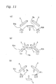
- the film holding portions 91a and 91b which are in a home position H.P. shown in Fig. 10(a), hold the laterally opposite sides of the stretch film Fm, and then are moved outward to stretch the stretch film Fm as shown in Fig. 10(b).
- the stretch mechanism 9 operates to stretch the stretch film Fm before pushing up the tray T against the stretch film Fm by the lift mechanism 6.
- the stretch film Fm is stretched by an amount, which will be referred to as a prestretch amount, and will be described later in greater detail.
- the stretch mechanism 9 operates to reduce the stretching force or tension applied to the stretch film Fm immediately after the tray T, which is being lifted by the lift mechanism 6, comes into contact with the stretch film Fm.
- both the film holding portions 91a and 91b are moved inward to reduce the tension of the stretch film Fm for a period after the tray T comes into contact with the stretch film Fm as shown in Fig. 10(c) and before the tray T reaches the upper limit as shown in Fig. 11(d).
- a certain tension is kept in the stretch film Fm even in the state where the tray T is in the highest position shown in Fig. 11(d).
- the rollers 3 weld the stretch film Fm to the tray T as shown in Fig. 11(e), and then the opposite film holding portions 91a and 91b are moved outward to stretch the stretch film Fm.
- the welding of the stretch film Fm to the tray T as well as the thermal cutting of the stretch film Fm are completed so that the rollers 3 are moved upward, and the tray T is lowered. Thereafter, the opposite film holding portions 91a and 91b of the stretch mechanism 9 return to the home position.
- the tray carrying and holding mechanism 2 is primarily formed of a casing 20, first to fourth tray holding members 21 - 24, lateral guide shafts 25, longitudinal guide shafts 26, link mechanisms 27a and 27b, coil springs 27d and 27e, first and second rollers 28a and 28b, and vertically movable guide members 29b.
- the casing 20 carries various members, and can move longitudinally (forward and backward) together with the longitudinally movable guide members 29a carrying the casing 20. Also, the casing 20 is guided by the vertically movable guide members 29b along vertical guide rails 69, and can be vertically moved by the lift mechanism 6.
- a fixed support plate 20a for carrying the tray T is fixed to the casing 20.
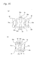
- the fixed support plate 20a is provided with recesses for avoiding interference with moving members, i.e., first to fourth tray holding members 21 - 24, as shown in Fig. 16.
- the first and second tray holding members 21 and 22 center the tray T in the lateral direction (i.e., performs the lateral positioning), and prevents the positional deviation of the tray T in the lateral direction by laterally holding the opposite sides of the tray T.
- the first and second tray holding portions 21 and 22 are provided at their upper portions with contact portions 21a and 22a for lateral contact with the opposite side surfaces of the tray T, respectively.
- the contact portions 21a and 22a are provided at their lower surfaces with tray lower surface support plates 21b and 22b extending inward, respectively.
- the tray lower surface support plates 21b and 22b can be located between the tray T and the fixed support plate 20a when the tray carrying and holding mechanism 2 moves horizontally to the position under the roller 3 (see Fig. 12).
- the third and fourth holding members 23 and 24 center the tray T in the longitudinal direction (i.e., performs the longitudinal positioning), and hold the longitudinally opposite sides of the tray T for preventing positional deviation in the longitudinal direction.
- the third and fourth tray holding members 23 and 24 are provided at their upper portions with contact portions 23a and 24a to be in longitudinal contact with the opposite side surfaces of the tray T.
- the first and second tray holding members 21 and 22 are supported by the link mechanism 27a for performing laterally and longitudinally symmetrical movements with respect to a central axis 27c
- the third and fourth tray holding members 23 and 24 are supported by the link mechanism 27b for performing laterally and longitudinally symmetrical movements with respect to the central axis 27c.
- the first and second tray holding members 21 and 22 are carried by the casing 20 via the lateral guide shafts 25
- the third and fourth tray holding members 23 and 24 are carried by the casing 20 via the longitudinal guide shafts 26.
- the opposite ends of each of the lateral and longitudinal guide shafts 25 and 26 are fixed to the casing 20.
- the link mechanism 27a is configured to be symmetrical with respect to the central axis 27c, and has opposite ends coupled via axes to the lower portions of the first and second tray holding members 21 and 22, respectively.
- the link mechanism 27a is biased by the coil spring 27d to move its opposite ends inward, as shown in Fig. 19.
- the link mechanism 27b is configured to be symmetrical with respect to the central axis 27c, and has the opposite ends coupled via axes to the lower portions of the third and fourth tray holding members 23 and 24, respectively.
- the link mechanism 27b is biased by the coil spring 27e to move its opposite ends inward, as shown in Fig. 19.
- the central axis 27c is arranged to be located on the center of the tray T when the lift mechanism 6 lifts the tray carrying and holding mechanism 2. More specifically, the central axis 27c is arranged on a straight line extending between the two pivot axes 81a and 81b in a plan view.
- the biasing means may be formed of an electric motor, a pneumatic cylinder, a hydraulic cylinder, or the like.
- the first roller 28a is restricted by a first roller guide member 1c integral with the frame 1a, and is rotatably carried by an end of a member, which extends from the lower portion of the first tray holding member 21 toward the longitudinally inner position.
- the second roller 28b is restricted by a second roller guide member 1d integral with the frame 1a, and is rotatably carried by an end of a member, which extends rightward from the lower portion of the fourth tray holding member 24.
- the vertically movable guide member 29b is fixed to the casing 20, and is vertically movably engaged with the vertical guide rail 69.
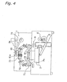
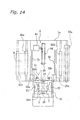
- the pulled-out state of the tray carrying and holding mechanism 2 is shown in Figs. 12, 14, 16(a), 17, and 19(a).
- the pushed-in state, where the tray carrying and holding mechanism 2 is horizontally moved to the position under the roller 3, is shown in Figs. 13, 15, 16(b), 18, and 19(b).
- the tray T is laid on the fixed support plate 20a in the upper portion of the casing 20, and the tray carrying and holding mechanism 2 is pushed to a position under the roller 3. Thereby, the tray carrying and holding mechanism 2 laid on the longitudinally movable guide member 29a moves horizontally to the pushed-in position.
- the longitudinally movable guide member 29a is longitudinally movably engaged with a pair of the horizontal guide rails 1b, which are integral with the frame 1a.
- the first roller 28a restricted by the first roller guide member 1c gradually moves rightward along the inclined surface of the first roller guide member 1c.
- the first roller guide member 1c no longer restricts the first roller 28a.
- the first and second tray holding members 21 and 22 biased by the coil spring 27d move inward, as shown in Figs. 16(b) and 19(b).
- the first and second tray holding members 21 and 22 move horizontally along the lateral guide shafts 25.
- the contact portions 21a and 22a of the first and second tray holding members 21 and 22 come into contact with the side surfaces of the tray T, and hold laterally opposite sides of the tray T so that the first and second tray holding members 21 and 22 stop their inward motion.
- the second roller 28b which has been restricted by the second roller guide member 1d, is disengaged therefrom, and is no longer restricted by the second roller guide member 1d.
- the third and fourth tray holding members 23 and 24 biased by the coil spring 27e move inward, as shown in Figs. 16(b) and 19(b).
- the third and fourth tray holding members 23 and 24 move horizontally along the longitudinal guide shafts 26.
- the contact portions 23a and 24a of the third and fourth tray holding members 23 and 24 come into contact with the side surfaces of the tray T, and hold the longitudinally opposite sides of the tray T so that the third and fourth tray holding members 23 and 24 stop their motion.
- the tray carrying and holding mechanism 2 When the tray carrying and holding mechanism 2 is pushed to the position under the roller 3 in the above manner, the first to fourth tray holding members 21 - 24 move toward the central axis 27c for centering the tray T, and the contact portions 21a - 24a hold the four side surfaces of the tray T, respectively (see Figs. 13(b) and 16(b)).
- the tray carrying and holding mechanism 2 holding the tray T is vertically lifted by the lift mechanism 6 along the vertical guide rail 69.
- the stretch film Fm Since the stretch film Fm has high elasticity and self-adhesion, it is difficult to pull out the wound stretch film Fm from the winding shaft if the winding shaft is merely made of a cylindrical member.
- the winding shaft may be formed of a paper tube or the like. However, it is desired to collect only the wound stretch film Fm for disposal or recycling.
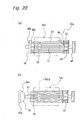
- the wrapping device 1 of this embodiment employs the winding shaft 53a shown in Fig. 20(a).
- the winding shaft 53a is formed of a support shaft 41, a fixed plate 42, winding guides 43, a guide plate 44, a guide pulley 45, a removable guide 46, a rubber belt 47, and a torque pulley 48.
- the plurality of winding guides 43 are swingably supported by the fixed plate 42.
- the guide plate 44 is provided with radially long apertures, through which the winding guides 43 extend, respectively. Therefore, the guide plate 44 allows swinging of the winding guides 43.
- the rubber belt 47 is arranged near the guide plate 44 for inwardly biasing the winding guides 43.
- the guide pulley 45 serves to adjust radial positions of the ends (left ends in Fig. 20) of the winding guides 43 with respect to the shaft 41 (see Fig. 20(b)).
- the removable guide 46 is formed of a circular plate portion 46a, which is in contact with the ends of the winding guides 43, and a guide portion 46b protruding from one end surface of the circular plate portion 46a into the winding guides 43. Except for a portion (left portion in Fig. 20) near the circular plate portion 46a, the guide portion 46b is tapered to converge toward the fixed plate 42.
- the removable guide 46 supports the inner sides of the ends of the winding guides 43, and holds the respective winding guides 43 in the parallel position.
- the belt 53b is retained around the torque pulley 48.
- the stretch film Fm is stretched by an amount (i.e., prestretch amount), which is determined based on the following parameters. These parameters can de determined by calling out the tray size, tray material and others, which are stored in the tray master file 14a, based on the entered tray number or the like.
- the optimum prestretch amount can be determined based on the relative relationship between the width of the stretch film Fm and the width of the tray T.
- the prestretch amount can be determined in view of the characteristics such as resistance to ripping based on the material.
- the prestretch amount can be determined in view of a variation of the hardness of the tray T depending on the temperature.
- the film holding portions 91a and 91b return to the inner positions when the film is pushed up by the tray T, and the timing and amount of this return are determined based on the above parameters.
- the size of the tray T to be wrapped is determined. Thereafter, the film transporting operation is performed. The amount of film transported in this operation may be determined in the following manners (M1) and (M2).
- a shortage does not occur, and the film transportation is not performed if the tray requires transportation of an amount that is equal to or smaller than that in the last operation. Only when the required amount of the transported film is larger than that in the last operation is the amount of the film corresponding to the shortage transported.
- the wrapping can be performed without transporting film if the tray size is equal to or smaller than that of the last tray.
- an excessive amount of film is transported if the new tray requires transportation of a smaller amount of film. Therefore, a large amount of film is wasted if the amount of transported film is frequently changed for flexible production (i.e., production of small batches of a variety of products).
- the above manner (M2) can prevent waste of film.
- the wrapping device 1 of the embodiment employs the manner (M2).
- the film changing is performed in the following manner.
- the stretch film Fm extending from the film roll R to the winding shaft 53a is cut at some midpoint, and the film roll R is removed. If the waste film Fm1 wound around the winding shaft 53a is large in volume, the removable guide 46 is removed as already described, and the waste film Fm1 is removed (see Fig. 20).
- the new film roll R is attached, and the stretch film Fm is extended via the payoff roller 52a and the film support roller 52d, and is wound around the winding shaft 53a.
- the seal unit is closed, and the stretch film Fm is fed by performing an idle operation two or three times. Thereby, the film changing operation is completed.
- the stretch film since the stretch film is wound after the thermal cutting, the thin stretch film having substantially no rigidity can be sent by the transporting mechanism in a compact structure. Since the stretch mechanism is employed for stretching the stretch film at least before welding the stretch film to the tray, wrinkles are, therefore, removed from the stretch film covering the opening of the tray, resulting in a good appearance in the wrapped state.
Landscapes
- Engineering & Computer Science (AREA)
- Mechanical Engineering (AREA)
- Closing Of Containers (AREA)
- Basic Packing Technique (AREA)
- Package Closures (AREA)
Abstract
Description
Claims (22)
- A top-seal wrapping device for covering a top opening of a tray containing a wrapping target with a stretch film, welding said stretch film to a peripheral portion of said tray around said opening and thermally cutting said the stretch film, comprising:a stretch mechanism for stretching said stretch film;a control portion for controlling the stretching of said stretch film by operating said stretch mechanism at least before welding said stretch film to said tray; anda film winding portion for winding up said stretch film after the thermal cutting.
- The top-seal wrapping device according to claim 1, wherein
said stretch film is thermally cut at a position outside a portion welded to the peripheral portion around said tray opening. - The top-seal wrapping device according to claim 1 or 2, wherein
said control portion operates said stretch mechanism to apply a tension to a portion of said stretch film near the cut portion at least after welding said stretch film. - The top-seal wrapping device according to claim 1, 2 or 3, further comprising:a film transporting mechanism for transporting said stretch film; anda lift mechanism for lifting said tray to push said stretch film transported by said film transporting mechanism against said tray, whereinsaid control portion operates said stretch mechanism to stretch said stretch film before contact of said tray with said stretch film, and also controls said stretch mechanism to reduce a tension of said stretch film after the contact of said tray with said stretch film.
- The top-seal wrapping device according to any one of the preceding claims, wherein
said stretch mechanism is arranged between a supply position of said stretch film and an end of a position of said welding. - The top-seal wrapping device according to any one of the preceding claims, further comprising:detecting means for detecting an opening in said stretch film formed by the thermal cutting, whereinsaid control portion controls said stretch mechanism not to act on at least a portion of said stretch film including and neighboring to the opening detected by said detecting means.
- The top-seal wrapping device according to any one of the preceding claims, wherein
said stretch mechanism has a plurality of film holding portions for holding said stretch film. - The top-seal wrapping device according to claim 7, wherein
said plurality of film holding portions can be set to have different holding forces, respectively. - The top-seal wrapping device according to claim 7 or 8, wherein
said control portion changes timing of holding and releasing operations of said plurality of film holding portions based on the properties of at least one of said tray and said stretch film. - The top-seal wrapping device according to any one of the preceding claims, wherein
said stretch mechanism stretches said stretch film in at least one of the transporting direction of said stretch film or the width direction perpendicular to said transporting direction. - A top-seal wrapping method for covering a top opening of a tray containing a wrapping target with a stretch film, welding said stretch film to a peripheral portion of said tray around said opening and thermally cutting said stretch film, comprising:a film supply step for transporting said stretch film to a position above said tray;a stretch step for stretching said stretch film in a direction crossing said transporting direction at least before welding said stretch film to said tray; anda film winding step for winding said stretch film after the thermal cutting.
- The top-seal wrapping device according to claim 1, further comprising:a film supply mechanism for supplying said stretch film to a position above said tray;a lift mechanism for lifting said tray to push said tray against said stretch film;a heating body for coming into contact with the peripheral portion of said tray surrounding the opening and being in contact with said stretch film for welding said stretch film to the peripheral portion of said tray around the opening; anda tray holding portion for holding said tray when welding said stretch film to the peripheral portion of said tray around said opening.
- The top-seal wrapping device according to claim 12, wherein
said tray holding member prevents shifting of the position of said tray when said tray is lifted and pushed against said stretch film. - The top-seal wrapping device according to claim 12 or 13, wherein
said tray holding member comes into contact with a side surface of said tray for preventing the shift of the planar position of said tray. - The top-seal wrapping device according to claim 12, 13 or 14, further comprising:a tray carrying and holding mechanism for carrying said tray thereon, and being transported to said lift mechanism together with said tray, whereinsaid tray holding member is included in said tray carrying and holding mechanism, andsaid lift mechanism lifts said tray by lifting said tray carrying and holding mechanism.
- The top-seal wrapping device according to any one of the claims 12 to 15, wherein
said tray carrying and holding mechanism biases said tray holding member toward said tray to adjust a planar position of said tray. - The top-seal wrapping device according to any one of the claims 12 to 14, further comprising:position detecting means for detecting a positional state of said tray during transportation to said lift mechanism, whereinsaid control portion corrects shifting of position of the tray by said tray holding member based on a result of a detection by said position detecting means.
- The top-seal wrapping device according to any one of the claims 12 to 14, further comprising:biasing means for biasing said tray holding member toward said tray, wherein said control portion controls a biasing force of said biasing means.
- The top-seal wrapping device according to claim 18, further comprising:biasing force detecting means for detecting the biasing force applied by said biasing means, whereinsaid control portion controls the biasing force of said biasing means based on a result of the detection by said biasing force detecting means.
- The top-seal wrapping device according to claim 18, wherein
said control portion controls the biasing force of said biasing means corresponding to the properties of at least one of said tray and said stretch film. - The top-seal wrapping device according to claim 1, further comprising:a film supply mechanism for supplying said stretch film to a position above said tray;a lift mechanism for lifting and pushing said tray against said stretch film;a heating body for coming into contact with the peripheral portion of said tray surrounding the opening and being in contact with said stretch film, and welding said stretch film to the peripheral portion of said tray around the opening; anda position adjusting mechanism for adjusting the planar position of said tray before said tray comes into contact with said stretch film.
- The top-seal wrapping method according to claim 11, further comprising:a position adjusting step for adjusting the planar position of said tray;a lift step for lifting and pushing said tray against said stretch film; anda welding step for bringing a heating body into contact with the peripheral portion of said tray located around said opening and being in contact with said stretch film, and thereby welding said stretch film to the peripheral portion of said tray around the opening.
Applications Claiming Priority (5)
| Application Number | Priority Date | Filing Date | Title |
|---|---|---|---|
| JP2000113550 | 2000-04-14 | ||
| JP2000113550A JP2001294210A (en) | 2000-04-14 | 2000-04-14 | Top seal type packaging device and top seal type packaging method |
| JP2000124002A JP2001301703A (en) | 2000-04-25 | 2000-04-25 | Top seal type packaging device and top seal type packaging method |
| JP2000124002 | 2000-04-25 | ||
| PCT/JP2001/002422 WO2001078973A1 (en) | 2000-04-14 | 2001-03-26 | Device and method for top seal packaging |
Publications (2)
| Publication Number | Publication Date |
|---|---|
| EP1273431A1 true EP1273431A1 (en) | 2003-01-08 |
| EP1273431A4 EP1273431A4 (en) | 2006-11-08 |
Family
ID=26590136
Family Applications (1)
| Application Number | Title | Priority Date | Filing Date |
|---|---|---|---|
| EP01915789A Withdrawn EP1273431A4 (en) | 2000-04-14 | 2001-03-26 | Device and method for top seal packaging |
Country Status (8)
| Country | Link |
|---|---|
| US (1) | US6718736B2 (en) |
| EP (1) | EP1273431A4 (en) |
| KR (1) | KR100423589B1 (en) |
| CN (1) | CN1154599C (en) |
| AU (1) | AU753970B2 (en) |
| NZ (1) | NZ516089A (en) |
| TW (1) | TW534889B (en) |
| WO (1) | WO2001078973A1 (en) |
Families Citing this family (17)
| Publication number | Priority date | Publication date | Assignee | Title |
|---|---|---|---|---|
| US8163251B2 (en) | 2001-09-10 | 2012-04-24 | Py Daniel C | Transfer port and method for transferring sterile items |
| US6834476B2 (en) * | 2002-10-17 | 2004-12-28 | Ibaraki Seiki Machinery Company, Ltd. | Sealing and packaging device for cover film on tray |
| US20060096249A1 (en) * | 2004-11-05 | 2006-05-11 | Hartness International, Inc. | Shrink wrap machine with film cutting mechanism, film cutting assembly, and related methods |
| US20060096248A1 (en) * | 2004-11-05 | 2006-05-11 | Hartness International, Inc. | Modifiable shrink wrap machine, assembly and related method |
| US7553437B2 (en) * | 2007-05-10 | 2009-06-30 | Sealed Air Corporation (Us) | Method and mold assembly for making a molded foam article |
| JP5727757B2 (en) * | 2009-12-25 | 2015-06-03 | 芝浦メカトロニクス株式会社 | Sealing can device |
| PL2822859T3 (en) * | 2012-03-07 | 2018-03-30 | Intercontinental Great Brands Llc | Systems and methods for sealing containers having a non-planar flange |
| JP6643804B2 (en) * | 2015-01-09 | 2020-02-12 | 国立大学法人北海道大学 | Rare earth metal complex and light emitting device using the same |
| JP6571938B2 (en) * | 2015-01-26 | 2019-09-04 | 株式会社イシダ | Packaging equipment |
| JP6577199B2 (en) * | 2015-02-09 | 2019-09-18 | 株式会社イシダ | Packaging system |
| US9662023B2 (en) | 2015-06-16 | 2017-05-30 | Qualcomm Incorporated | Robust heart rate estimation |
| DE102016111357A1 (en) | 2016-06-10 | 2017-12-14 | Weber Maschinenbau Gmbh Breidenbach | Device for transporting objects |
| KR101985918B1 (en) * | 2017-09-21 | 2019-06-04 | (주)흥아기연 | Sealing apparatus for packing blister |
| CN109049728A (en) * | 2018-09-30 | 2018-12-21 | 宁波飞图自动技术有限公司 | A kind of medical films band earnestly welds integrated device and welding method |
| EP4122834B1 (en) * | 2020-03-16 | 2025-12-10 | Yakult Honsha Co., Ltd. | Heat-sealing device |
| AT525393B1 (en) * | 2021-08-25 | 2023-08-15 | Mondi Ag | Device, arrangement and method for wrapping cargo with a paper web |
| IT202100029924A1 (en) * | 2021-11-26 | 2023-05-26 | Tosa S P A | Machinery for wrapping an article, having a return system |
Family Cites Families (22)
| Publication number | Priority date | Publication date | Assignee | Title |
|---|---|---|---|---|
| US3017729A (en) * | 1959-05-26 | 1962-01-23 | Reynolds Metals Co | Shrinkable container closure and manufacture thereof |
| GB1083578A (en) * | 1963-09-05 | 1967-09-13 | Parnall & Sons Ltd | Improvements in apparatus for closing open-topped packaging containers with thermoplastic sheet material |
| GB1161022A (en) * | 1965-09-01 | 1969-08-13 | American Can Co | Improvements in vacuum packaging |
| US3460317A (en) * | 1965-09-03 | 1969-08-12 | Universal Machine Co Inc | Machine for applying film covers to containers |
| CH520016A (en) * | 1971-03-18 | 1972-03-15 | Tourpac Ag | Device for the production of filled evacuated packs and method of operating the device |
| US3777452A (en) * | 1971-05-03 | 1973-12-11 | E Koenders | Packing machine |
| US3874145A (en) * | 1971-06-08 | 1975-04-01 | Max Schmidt | Covering- or sealing-apparatus for food-containers which are filled, preferably, with frozen foods |
| US3979877A (en) * | 1974-08-01 | 1976-09-14 | Multivac Sepp Haggenmueller Kg | Vacuum packaging machine with web registration means |
| FR2601330B1 (en) * | 1986-07-09 | 1989-07-28 | Robache Roger | MACHINE FOR CLOSING A TRAY, OR OTHER PACKAGING CONTAINER, BY WELDING A THERMO-PLASTIC FILM ON THE EDGES OF SUCH A CONTAINER |
| JPH0811564B2 (en) * | 1989-12-31 | 1996-02-07 | 東洋機械金属株式会社 | Product centering mechanism and its sensing method in automatic product packaging machine |
| JP2568423Y2 (en) * | 1992-03-06 | 1998-04-15 | 四国化工機株式会社 | Container sealing device |
| EP0569615A1 (en) * | 1992-05-15 | 1993-11-18 | A.W.A.X. PROGETTAZIONE E RICERCA S.r.l. | Process and machine for wrapping articles in a stretchable film |
| US5473861A (en) | 1992-10-30 | 1995-12-12 | Teraoka Seiko Co., Ltd. | Packing method and packing apparatus |
| JPH06270912A (en) * | 1993-03-12 | 1994-09-27 | Ishida Co Ltd | Wrapping apparatus |
| JP3597559B2 (en) * | 1994-03-30 | 2004-12-08 | 王子製袋株式会社 | Automatic Spiral Stretch Wrapping Machine with Film Splicer |
| US5943844A (en) * | 1996-05-31 | 1999-08-31 | Ross Industries, Inc. | Method of wrapping a food product, packaging machine used and package formed |
| US5718101A (en) * | 1996-06-04 | 1998-02-17 | W. R. Grace & Co.-Conn. | Method and apparatus for packaging a product in a dual-lid package |
| JP3233643B2 (en) * | 1996-07-08 | 2001-11-26 | クライオバツク・インコーポレイテッド | Hermetic hermetic packaging and its manufacturing method and manufacturing machine |
| JP3855381B2 (en) * | 1997-07-04 | 2006-12-06 | シブヤマシナリー株式会社 | Weight filling equipment |
| JP3143438B2 (en) | 1998-09-21 | 2001-03-07 | 株式会社クボタ | Adjusting structure of vertical feeder of rice transplanter |
| US6021629A (en) * | 1998-10-12 | 2000-02-08 | Sks Equipment Co, Inc. | Registration system for sealed tray packaging machine |
| KR20010052466A (en) * | 1999-05-18 | 2001-06-25 | 이시다 다게시 | Packaging method and packaging apparatus |
-
2001
- 2001-03-26 NZ NZ516089A patent/NZ516089A/en unknown
- 2001-03-26 WO PCT/JP2001/002422 patent/WO2001078973A1/en not_active Ceased
- 2001-03-26 AU AU42786/01A patent/AU753970B2/en not_active Ceased
- 2001-03-26 US US09/980,639 patent/US6718736B2/en not_active Expired - Fee Related
- 2001-03-26 CN CNB018009360A patent/CN1154599C/en not_active Expired - Fee Related
- 2001-03-26 KR KR10-2001-7013927A patent/KR100423589B1/en not_active Expired - Fee Related
- 2001-03-26 EP EP01915789A patent/EP1273431A4/en not_active Withdrawn
- 2001-04-13 TW TW090108959A patent/TW534889B/en not_active IP Right Cessation
Also Published As
| Publication number | Publication date |
|---|---|
| US20020152726A1 (en) | 2002-10-24 |
| KR20020026158A (en) | 2002-04-06 |
| US6718736B2 (en) | 2004-04-13 |
| KR100423589B1 (en) | 2004-03-22 |
| EP1273431A4 (en) | 2006-11-08 |
| TW534889B (en) | 2003-06-01 |
| NZ516089A (en) | 2003-04-29 |
| CN1366488A (en) | 2002-08-28 |
| CN1154599C (en) | 2004-06-23 |
| AU4278601A (en) | 2001-10-30 |
| WO2001078973A1 (en) | 2001-10-25 |
| AU753970B2 (en) | 2002-10-31 |
Similar Documents
| Publication | Publication Date | Title |
|---|---|---|
| AU753970B2 (en) | Device and method for top seal packaging | |
| KR20010052466A (en) | Packaging method and packaging apparatus | |
| JP4249889B2 (en) | Seal check device | |
| JP7207681B2 (en) | packaging equipment | |
| KR102795532B1 (en) | Packing Tape Attaching Apparatus For In-Line Bundle Packing Product | |
| JP3184622B2 (en) | Packaging equipment | |
| JP2001301704A (en) | Top seal type packaging device and top seal type packaging method | |
| KR102088015B1 (en) | Strapping Machine | |
| JP4070997B2 (en) | Packaging apparatus and initial setting method in packaging apparatus | |
| JP2001294210A (en) | Top seal type packaging device and top seal type packaging method | |
| JP3889622B2 (en) | Packaging equipment | |
| JP3954846B2 (en) | Packaging equipment | |
| JP2003081204A (en) | Packaging device and packaging method | |
| JP3920665B2 (en) | Packaging equipment | |
| JP3712205B2 (en) | Automatic packaging equipment and consumables used in automatic packaging equipment | |
| JP2001328608A (en) | Top seal type packaging equipment | |
| JP2582645B2 (en) | Product packaging method and equipment | |
| US11685560B2 (en) | Packaging device and packaging method for packaging material | |
| JP2907098B2 (en) | Stretch film packaging machine | |
| JP2582646B2 (en) | Product packaging method and equipment | |
| JPH01240411A (en) | Method and apparatus for film packaging | |
| JP3920646B2 (en) | Packaging equipment | |
| JPH0534109U (en) | End seal device | |
| JPH01240414A (en) | Film packaging method | |
| JP2008162604A (en) | Apparatus for sealing spout of bag packaging food product |
Legal Events
| Date | Code | Title | Description |
|---|---|---|---|
| PUAI | Public reference made under article 153(3) epc to a published international application that has entered the european phase |
Free format text: ORIGINAL CODE: 0009012 |
|
| 17P | Request for examination filed |
Effective date: 20020110 |
|
| AK | Designated contracting states |
Kind code of ref document: A1 Designated state(s): DE DK ES FR GB IT NL SE |
|
| AX | Request for extension of the european patent |
Free format text: AL;LT;LV;MK;RO;SI |
|
| A4 | Supplementary search report drawn up and despatched |
Effective date: 20061010 |
|
| RIC1 | Information provided on ipc code assigned before grant |
Ipc: B31B 17/60 20060101AFI20011101BHEP Ipc: B65B 7/16 20060101ALI20061004BHEP |
|
| STAA | Information on the status of an ep patent application or granted ep patent |
Free format text: STATUS: THE APPLICATION IS DEEMED TO BE WITHDRAWN |
|
| 18D | Application deemed to be withdrawn |
Effective date: 20061228 |