EP1273397B1 - Carrying and charging cases for a battery operated electric tool and set of such cases - Google Patents
Carrying and charging cases for a battery operated electric tool and set of such cases Download PDFInfo
- Publication number
- EP1273397B1 EP1273397B1 EP20020010531 EP02010531A EP1273397B1 EP 1273397 B1 EP1273397 B1 EP 1273397B1 EP 20020010531 EP20020010531 EP 20020010531 EP 02010531 A EP02010531 A EP 02010531A EP 1273397 B1 EP1273397 B1 EP 1273397B1
- Authority
- EP
- European Patent Office
- Prior art keywords
- case
- charging
- electrical contacts
- battery
- charging case
- Prior art date
- Legal status (The legal status is an assumption and is not a legal conclusion. Google has not performed a legal analysis and makes no representation as to the accuracy of the status listed.)
- Expired - Lifetime
Links
- 238000003032 molecular docking Methods 0.000 claims description 9
- 230000004308 accommodation Effects 0.000 claims 2
- 230000001419 dependent effect Effects 0.000 description 1
- 238000004519 manufacturing process Methods 0.000 description 1
- 238000004806 packaging method and process Methods 0.000 description 1
- 230000007306 turnover Effects 0.000 description 1
Images

Classifications
-
- B—PERFORMING OPERATIONS; TRANSPORTING
- B25—HAND TOOLS; PORTABLE POWER-DRIVEN TOOLS; MANIPULATORS
- B25H—WORKSHOP EQUIPMENT, e.g. FOR MARKING-OUT WORK; STORAGE MEANS FOR WORKSHOPS
- B25H3/00—Storage means or arrangements for workshops facilitating access to, or handling of, work tools or instruments
- B25H3/006—Storage means specially adapted for one specific hand apparatus, e.g. an electric drill
Definitions
- the invention relates to a transport case for a battery-powered power tool with the generic features of claim 1, and a charging case with the generic features of claim 3.
- Such a transport case is known from the US-A-5533843 and such a charging case is known from the DE-A1-19614435 ,
- combo kits known in which several battery-powered power tools are sold in a set. It is a set of power tools that are delivered in a single carrying case. As a result, a separate battery pack or charger does not have to be enclosed with each individual power tool. A buyer can thereby buy several battery-powered power tools at a cheaper price, since the number of rechargeable batteries or chargers is lower than if he would individually buy a battery-powered power tool with the associated battery pack or charger. The manufacturer also saves costs in terms of logistics and packaging. The fact that the power tools can be offered cheaper, more power tools are sold and both the turnover and the number of units of the manufacturer is increased.
- the transport case is unwieldy and difficult, because in it a heavy charger or battery packs must be enclosed.
- the customer can only purchase the power tools specifically offered in the set in their entirety. This may force him to purchase a power tool he does not need.
- An inventive transport case with the features of claim 1 and a charging case according to the invention with the features of claim 3 have the advantage that an individual compilation of the required battery-powered power tools by the buyer is possible and he is not constantly a heavy transport case with a variety of power tools and Battery packs or chargers must carry with them.
- the transport case according to the invention in that it can be connected via its first connecting device, which is arranged on one of its outer surfaces, with a charging case according to the invention via the second connecting device, which is also arranged on an outer surface.
- a charging case according to the invention via the second connecting device, which is also arranged on an outer surface.
- an inventive set of at least one transport case and a charging case is formed.
- charging of a battery powered power tool in the receiving bay of the carrying case may occur when the power cord of the charging case is connected to a power source.
- the set can be disassembled again in transport case and charging case. If only small jobs need to be done, it is possible to dispense with the carrying of the heavy loading case and only carry the transport case with the specifically required power tool.
- the charging case With the charging case, it is always possible to combine precisely the transport case into a set, which is needed for the battery-powered power tool just needed. Thus, a buyer does not have to buy a large combo kit with different power tools, but can each buy a single case with just a battery-powered power tool.
- the first connection device forms a secure and detachable connection unit on the transport case with the second connection device on the charging case. This ensures that charging of the battery-powered power tool located in the transport case takes place.
- a transport case having at each of its outer surfaces a further first connection device and further electrical contacts which are connected to the first electrical contacts.
- This makes it possible to dock on this transport case another transport case for another battery-powered power tool. It can be a different or even the same power tool.
- it is possible to assemble your own, individual set of just needed power tools.
- the fact that the second electrical contacts are connected to the first electrical contacts it is ensured that when the charging case and the other transport case is supplied with power and thus it is located in a battery-powered power tool is charged.
- the charging case has at least one charging bay for a battery pack. This makes it possible to load a spare battery pack at the same time as a battery-powered power tool in a transport case. If no carrying case is connected to the charging case, only the spare battery pack can be charged in the charging case.
- a further advantageous embodiment of a charging case provides that the power cord is connected to a force extendable connected to him. This automatically retracts the power cord whenever it is not plugged into a wall outlet. Thus, the power cord does not have to be wound up by hand repeatedly on the charging case, but stows itself automatically in this. This principle is known from vacuum cleaners.
- the first or second connection device are designed as a latching device or a rail.
- This charging case and carrying case or even transport case with each other can be very easily docked together. In this case, this can then be done in a particularly simple manner by clipping on, plugging or pushing.
- FIG. 1 is a central transport case 1, which is referred to below as the base case 1 shown.
- This base case 1 has in its interior a receiving bay for a battery-powered power tool (not shown).
- electrical charging contacts (not shown) are arranged, which are electrically in contact with an inserted power tool with corresponding charging contacts on this or its battery pack.
- the base case 1 has a first connection device 2 with first electrical contacts 3.
- the first electrical contacts 3 are connected to the charging contacts of the receiving bay.
- a loading case 4 is brought along a first arrow P1 and docked to the base case 1. Docking can be clipping, hooking or suspending.
- a first docking device and on an outer surface of the loading case 4 are formed.
- These docking devices are designed to work together to provide a secure, detachable connection unit.
- Such docking devices are known, for example, there are locking devices or rails, so that it need not be discussed in detail here.
- the first electrical contacts 3 of the base case 1 with the second electrical contacts 8 of a second connecting device 7 on the charging case 4 in electrical contact.
- a battery pack in a power tool which is located in the receiving bay of the base 1, loaded by the charger 4.
- the base case 1 not only has a first connecting device 2 on its narrow outer surface, but also further first connecting devices on further outer surfaces 2a with further electrical contacts 3a. Representative of this is in FIG. 1 only a single further first connection device 2a is shown.
- further transport cases 1a, 1b, 1c can be docked to the base case 1 along the respective directions, which are represented by the arrows P2, P3, P4.
- the further transport cases 1a, 1b, 1c each have further first connection devices 2a with further electrical contacts 3a. In the docked state, their respective further electrical contacts 3a have electrical contact with the further electrical contacts 3a of the base case 1.
- the other transport cases 1a, 1b, 1c is also a receiving bay for a battery-powered power tool (not shown) with charging contacts available, as was already above the base case 1 was executed.
- a battery-powered power tool (not shown) with charging contacts available, as was already above the base case 1 was executed.
- These may include any battery powered power tool. It is possible that it is a same power tool as in the base case 1 or a different one.
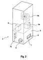
- FIG. 2 is an embodiment of an in FIG. 1 described charging case 4. This has several variants, which can either all be realized in a single charging case 4 or each individual variant also separately in a separate charging case. 4
- the charging case 4 has in its interior a charger 5.
- the charger 5 is connected via a power cord 6 with an external power source, such as a power outlet, connectable.
- a second connecting device 7 with second electrical contacts 8 is arranged on one of the outer surfaces of the charging case 4. This is connected to the charger 5.
- the second electrical contacts 8 are in the docked state, as to FIG. 1 described above, with the first electrical contacts 3 of the base case 1 in electrical contact.
- the charging case 4 has a further second connecting device 7a, which is arranged on a further outer surface of the charging case 4, which is opposite to the second connecting device 7. This makes it possible to connect another base case 1 directly to the charging case 4. Thus, an even larger number of power tools can be loaded simultaneously by the charging case 4.
- the power cord 6 is designed so that it against a force, usually a spring force, back into the charging case 4 is pulled in if it is not in a socket or other power source. This is comparable to a system known from vacuum cleaners. It is an automatic retractor. As a variant, another power cord 6 a is shown in dashed lines, which must be wound onto the charging case 4 by hand. This further power cable 6a is of course connected to the charger 5 and supplies it with power.
- the charging case 4 may have one or more charging bays for a replacement battery pack 9 or further replacement battery packs 9a. This can be done simultaneously with the charging of power tools, the pads of spare battery packs 9, 9a. Thus, it is possible to operate the power tool, after the battery pack is empty, with the replacement battery pack 9 or other spare battery packs 9a over a significantly longer period off-grid.
Description
Die Erfindung geht aus von einem Transportkoffer für ein akkubetriebenes Elektrowerkzeug mit den gattungsbildenden Merkmalen des Anspruchs 1, sowie einem Ladekoffer mit den gattungsbildenden Merkmalen des Anspruchs 3.The invention relates to a transport case for a battery-powered power tool with the generic features of claim 1, and a charging case with the generic features of claim 3.
Ein solcher Transportkoffer ist bekannt aus der
Es sind so genannte Kombo-Kits bekannt, bei denen mehrere akkubetriebene Elektrowerkzeuge in einem Set verkauft werden. Dabei handelt es sich um eine festgelegte Auswahl an Elektrowerkzeugen, die in einem einzigen Transportkoffer geliefert werden. Dadurch muss nicht jedem einzelnen Elektrowerkzeug ein separater Akku-Pack bzw. ein Ladegerät beigelegt werden. Ein Käufer kann dadurch mehrere akkubetriebene Elektrowerkzeuge zu einem günstigeren Preis kaufen, da die Anzahl der Akku-Packs bzw. Ladegeräte geringer ist, als wenn er sich jeweils einzeln ein akkubetriebenes Elektrowerkzeug mit dem dazugehörigen Akku-Pack bzw. Ladegerät zulegen würde. Auch der Hersteller spart dabei Kosten hinsichtlich der Logistik und der Verpackung ein. Dadurch, dass die Elektrowerkzeuge preisgünstiger angeboten werden können, werden mehr Elektrowerkzeuge abgesetzt und sowohl der Umsatz als auch die Stückzahl des Herstellers wird erhöht.There are so-called combo kits known in which several battery-powered power tools are sold in a set. It is a set of power tools that are delivered in a single carrying case. As a result, a separate battery pack or charger does not have to be enclosed with each individual power tool. A buyer can thereby buy several battery-powered power tools at a cheaper price, since the number of rechargeable batteries or chargers is lower than if he would individually buy a battery-powered power tool with the associated battery pack or charger. The manufacturer also saves costs in terms of logistics and packaging. The fact that the power tools can be offered cheaper, more power tools are sold and both the turnover and the number of units of the manufacturer is increased.
Für einen Käufer ergeben sich jedoch auch gravierende Nachteile. Zum Einen ist der Transportkoffer unhandlich und schwer, da in ihm ein schweres Ladegerät bzw. Akku-Packs beigelegt sein müssen. Zum Anderen kann der Kunde nur die speziell in dem Set angebotenen Elektrowerkzeuge in ihrer Gesamtheit erwerben. Dadurch wird er möglicherweise dazu genötigt, ein Elektrowerkzeug mit anzuschaffen, das er gar nicht benötigt.For a buyer, however, there are also serious disadvantages. For one, the transport case is unwieldy and difficult, because in it a heavy charger or battery packs must be enclosed. On the other hand, the customer can only purchase the power tools specifically offered in the set in their entirety. This may force him to purchase a power tool he does not need.
Ein erfindungsgemäßer Transportkoffer mit den Merkmalen des Anspruchs 1 sowie ein erfindungsgemäßer Ladekoffer mit den Merkmalen des Anspruchs 3 haben demgegenüber den Vorteil, dass eine individuelle Zusammenstellung der benötigten akkubetriebenen Elektrowerkzeuge durch den Käufer möglich ist und er nicht ständig einen schweren Transportkoffer mit einer Vielzahl von Elektrowerkzeugen sowie Akku-Packs bzw. Ladegeräten mit sich führen muss.An inventive transport case with the features of claim 1 and a charging case according to the invention with the features of claim 3 have the advantage that an individual compilation of the required battery-powered power tools by the buyer is possible and he is not constantly a heavy transport case with a variety of power tools and Battery packs or chargers must carry with them.
Dies wird beim erfindungsgemäßen Transportkoffer dadurch erreicht, dass er über seine erste Verbindungsvorrichtung, die an einer seiner Außenflächen angeordnet ist, mit einem erfindungsgemäßen Ladekoffer über dessen zweite Verbindungsvorrichtung, die ebenfalls an einer Außenfläche angeordnet ist, verbunden werden kann. Dadurch wird ein erfindungsgemäßes Set aus mindestens einem Transportkoffer und einem Ladekoffer gebildet. Somit kann ein Aufladen eines akkubetriebenen Elektrowerkzeuges in der Aufnahmebucht des Transportkoffers erfolgen, wenn das Netzkabel des Ladekoffers mit einer Stromquelle verbunden ist. Zum Transport kann das Set wieder in Transportkoffer und Ladekoffer zerlegt werden. Falls nur kleine Arbeiten erledigt werden müssen, kann auf die Mitnahme des schweren Ladekoffers verzichtet werden und nur der Transportkoffer mit dem spezifisch benötigten Elektrowerkzeug mitgeführt werden. Mit dem Ladekoffer kann immer genau der Transportkoffer zu einem Set zusammengefasst werden, der für das gerade benötigte akkubetriebene Elektrowerkzeug gebraucht wird. Dadurch muss ein Käufer nicht ein großes Kombo-Kit mit unterschiedlichen Elektrowerkzeugen kaufen, sondern kann jeweils einen einzelnen Koffer mit nur einem akkubetriebenen Elektrowerkzeug kaufen. Wenn der Transportkoffer mit dem Ladekoffer zu einem Set vereinigt wird, bildet die erste Verbindungsvorrichtung am Transportkoffer mit der zweiten Verbindungsvorrichtung am Ladekoffer eine sichere und lösbare Verbindungseinheit. Damit wird gewährleistet, dass ein Aufladen des sich im Transportkoffer befindlichen akkubetriebenen Elektrowerkzeugs erfolgt.This is achieved in the transport case according to the invention in that it can be connected via its first connecting device, which is arranged on one of its outer surfaces, with a charging case according to the invention via the second connecting device, which is also arranged on an outer surface. As a result, an inventive set of at least one transport case and a charging case is formed. Thus, charging of a battery powered power tool in the receiving bay of the carrying case may occur when the power cord of the charging case is connected to a power source. For transport, the set can be disassembled again in transport case and charging case. If only small jobs need to be done, it is possible to dispense with the carrying of the heavy loading case and only carry the transport case with the specifically required power tool. With the charging case, it is always possible to combine precisely the transport case into a set, which is needed for the battery-powered power tool just needed. Thus, a buyer does not have to buy a large combo kit with different power tools, but can each buy a single case with just a battery-powered power tool. When the transport case is combined with the charging case to form a set, the first connection device forms a secure and detachable connection unit on the transport case with the second connection device on the charging case. This ensures that charging of the battery-powered power tool located in the transport case takes place.
Vorteilhaft ist ein Transportkoffer, der an jeder seiner Außenflächen eine weitere erste Verbindungsvorrichtung und weitere elektrische Kontakte aufweist, die mit den ersten elektrischen Kontakten verbunden sind. Dadurch ist es möglich, an diesen Transportkoffer einen weiteren Transportkoffer für ein weiteres akkubetriebenen Elektrowerkzeug anzudocken. Dabei kann es sich um ein anderes oder auch um ein gleiches Elektrowerkzeug handeln. Somit ist es möglich, sich ein eigenes, individuelles Set von gerade benötigten Elektrowerkzeugen zusammenzustellen. Dadurch, dass die zweiten elektrischen Kontakte mit den ersten elektrischen Kontakten verbunden sind, ist gewährleistet, dass beim angeschlossenen Ladekoffer auch der weitere Transportkoffer mit Strom versorgt wird und somit ein sich darin befindliches akkubetriebenes Elektrowerkzeug geladen wird.Advantageously, a transport case having at each of its outer surfaces a further first connection device and further electrical contacts which are connected to the first electrical contacts. This makes it possible to dock on this transport case another transport case for another battery-powered power tool. It can be a different or even the same power tool. Thus, it is possible to assemble your own, individual set of just needed power tools. The fact that the second electrical contacts are connected to the first electrical contacts, it is ensured that when the charging case and the other transport case is supplied with power and thus it is located in a battery-powered power tool is charged.
Eine vorteilhafte Weiterbildung des Ladekoffers sieht vor, dass er mindestens eine Ladebucht für einen Akku-Pack aufweist. Dadurch ist es möglich, gleichzeitig mit einem sich in einem Transportkoffer befindlichen akkubetriebenen Elektrowerkzeug noch einen Ersatzakku-Pack zu laden. Falls an den Ladekoffer kein Transportkoffer angeschlossen ist, kann auch nur der Ersatzakku-Pack im Ladekoffer geladen werden.An advantageous development of the charging case provides that it has at least one charging bay for a battery pack. This makes it possible to load a spare battery pack at the same time as a battery-powered power tool in a transport case. If no carrying case is connected to the charging case, only the spare battery pack can be charged in the charging case.
Eine weitere vorteilhafte Weiterbildung eines Ladekoffers sieht vor, dass das Netzkabel gegen eine Kraft ausziehbar mit ihm verbunden ist. Dadurch wird das Netzkabel immer wieder automatisch zurückgezogen, wenn es nicht in einer Steckdose eingesteckt ist. Somit muss das Netzkabel nicht von Hand immer wieder auf den Ladekoffer aufgewickelt werden, sondern verstaut sich automatisch selbst in diesem. Dieses Prinzip ist von Staubsaugern bekannt.A further advantageous embodiment of a charging case provides that the power cord is connected to a force extendable connected to him. This automatically retracts the power cord whenever it is not plugged into a wall outlet. Thus, the power cord does not have to be wound up by hand repeatedly on the charging case, but stows itself automatically in this. This principle is known from vacuum cleaners.
Besonders vorteilhaft sind die erste bzw. zweite Verbindungsvorrichtung als eine Rastvorrichtung oder eine Schiene ausgebildet. Damit können Ladekoffer und Transportkoffer bzw. auch Transportkoffer untereinander sehr einfach aneinander angedockt werden. In diesem Fall kann dies dann in besonders einfacher Weise durch Anklipsen, Anstecken oder Aufschieben erfolgen.Particularly advantageously, the first or second connection device are designed as a latching device or a rail. This charging case and carrying case or even transport case with each other can be very easily docked together. In this case, this can then be done in a particularly simple manner by clipping on, plugging or pushing.
Weitere vorteilhafte Ausgestaltungen der Erfindung sind Gegenstand der Unteransprüche.Further advantageous embodiments of the invention are the subject of the dependent claims.
Ein Ausführungsbeispiel der Erfindung ist in der nachstehenden Beschreibung an Hand der zugehörigen Zeichnung näher erläutert.An embodiment of the invention is explained in more detail in the following description with reference to the accompanying drawings.
Die Figuren zeigen:
- Figur 1
- eine schematische Darstellung für die Zusammenstellung eines Sets aus einem Ladekoffer und mehreren Transportkoffern und
Figur 2- eine mögliche Ausgestaltung eines Ladekoffers.
- FIG. 1
- a schematic representation of the composition of a set of a charging case and several transport cases and
- FIG. 2
- a possible embodiment of a charging case.
In
Der Basiskoffer 1 weist nicht nur an seiner schmalen Außenfläche eine erste Verbindungsvorrichtung 2 auf, sondern auch noch an weiteren Außenflächen weitere erste Verbindungsvorrichtungen 2a mit weiteren elektrischen Kontakten 3a. Stellvertretend hierfür ist in
Durch das Herstellen eines solchen Sets aus mehreren Transportkoffern 1, 1a, 1b, 1c und einem einzigen Ladekoffer 4 ist es möglich, auf sehr engem Raum eine Vielzahl von akkubetriebenen Elektrowerkzeugen gleichzeitig zu laden. Außerdem ist es möglich, dass sich der Käufer die Elektrowerkzeuge zusammenstellt, die er persönlich benötigt und nicht ein vorgegebenes Kombo-Kit kaufen muss. Durch die individuelle Zusammenstellung der Elektrowerkzeuge kann der Käufer Geld sparen. Außerdem wird dadurch vermieden, dass ein Käufer ständig einen großen Transportkoffer mit einer Vielzahl von Elektrowerkzeugen mit sich tragen muss, wenn er doch nur ein spezifisches Elektrowerkzeug benötigt. Außerdem kann für kurze Einsätze auch auf die Mitnahme des Ladekoffers 4 verzichtet werden, was eine enorme Erleichterung darstellt, da der Ladekoffer 4 sehr schwer ist.By manufacturing such a set of a plurality of carrying
In
Der Ladekoffer 4 weist in seinem Inneren ein Ladegerät 5 auf. Das Ladegerät 5 ist über ein Netzkabel 6 mit einer externen Stromquelle, beispielsweise einer Steckdose, verbindbar. An einer der Außenflächen des Ladekoffers 4 ist eine zweite Verbindungsvorrichtung 7 mit zweiten elektrischen Kontakten 8 angeordnet. Diese ist mit dem Ladegerät 5 verbunden. Die zweiten elektrischen Kontakte 8 sind im angedockten Zustand, wie zu
Das Netzkabel 6 ist so ausgebildet, dass es gegen eine Kraft, in der Regel eine Federkraft, wieder in den Ladekoffer 4 hineingezogen wird, wenn es sich nicht in einer Steckdose oder einer sonstigen Stromquelle befindet. Dies ist einem System vergleichbar, das von Staubsaugern her bekannt ist. Es handelt sich um eine automatische Aufrollvorrichtung. Als Variante ist ein weiteres Netzkabel 6a gestrichelt dargestellt, das auf den Ladekoffer 4 von Hand aufgewickelt werden muss. Auch dieses weitere Netzkabel 6a ist natürlich mit dem Ladegerät 5 verbunden und versorgt dieses mit Strom.The
Als weitere Variante kann der Ladekoffer 4 eine oder mehrere Ladebuchten für einen Ersatzakku-Pack 9 bzw. weitere Ersatzakku-Packs 9a aufweisen. Damit kann gleichzeitig mit dem Aufladen von Elektrowerkzeugen das Auflagen von Ersatzakku-Packs 9, 9a erfolgen. Somit ist es möglich, das Elektrowerkzeug, nach dem dessen Akku-Pack leer ist, mit dem Ersatzakku-Pack 9 bzw. weiteren Ersatzakku-Packs 9a über einen bedeutend längeren Zeitraum netzunabhängig zu betreiben.As a further variant, the charging case 4 may have one or more charging bays for a
Claims (9)
- Carry case (1, 1a, 1b, 1c) for a battery-operated electric tool, comprising an accommodation receptacle for the electric tool, characterized in that it has a first connection apparatus (2) on at least one of its outer faces, with first electrical contacts (3) which are connected to charging contacts in the accommodation receptacle being formed on this outer face.
- Carry case (1, 1a, 1b, 1c) according to the preceding claim, characterized in that it has a further first connection apparatus (2a) and further electrical contacts (3a), which are connected to the first electrical contacts (3), on each of its outer faces.
- Charging case (4) for a battery-operated electric tool, comprising an internal charging device (5) and an external mains cable (6, 6a) which is connected to the said charging device, with the said charging case having a second connection apparatus (7) on at least one of its outer faces, characterized in that second electrical contacts (8) which are connected to the charging device (5) are formed on this outer face.
- Charging case (4) according to the preceding claim, characterized in that it has a further second connection apparatus (7a) and further third contacts, which are connected to the charging device (5), on each of its outer faces.
- Charging case (4) according to either of the preceding Claims 3 and 4, characterized in that it has at least one charging receptacle for a battery pack (9, 9a).
- Charging case (4) according to one of the preceding Claims 3 to 5, characterized in that the mains cable (6) is connected to the said charging case such that it can be pulled out against a force.
- Carry case (1, 1a, 1b, 1c) and/or charging case (4) according to one of the preceding claims, characterized in that they each have a first and second docking apparatus, for example a latching apparatus or a rail.
- Set comprising at least one carry case (1, 1a 1b, 1c) and a charging case (4) according to one of the preceding claims, characterized in that the carry case (1, 1a, 1b, 1c) can be connected to the second connection apparatus (7) of the charging case (4) by means of the first connection apparatus (2) such that the first electrical contacts (3) are continuously in contact with the third electrical contacts (8), with a first and a second docking apparatus interacting as a secure, releasable connection unit.
- Set according to the preceding claim, characterized in that a further carry case (1a, 1b, 1c) can be attached to the carry case (1) which is connected to the charging case (4) such that their respective first contacts (2a) are continuously in contact with one another and their respective first docking apparatuses interact as a secure, releasable connection unit.
Applications Claiming Priority (2)
| Application Number | Priority Date | Filing Date | Title |
|---|---|---|---|
| DE2001132830 DE10132830A1 (en) | 2001-07-06 | 2001-07-06 | Transport case and charging case for a battery-operated power tool as well as a set made of these cases |
| DE10132830 | 2001-07-06 |
Publications (2)
| Publication Number | Publication Date |
|---|---|
| EP1273397A1 EP1273397A1 (en) | 2003-01-08 |
| EP1273397B1 true EP1273397B1 (en) | 2008-02-20 |
Family
ID=7690859
Family Applications (1)
| Application Number | Title | Priority Date | Filing Date |
|---|---|---|---|
| EP20020010531 Expired - Lifetime EP1273397B1 (en) | 2001-07-06 | 2002-05-10 | Carrying and charging cases for a battery operated electric tool and set of such cases |
Country Status (2)
| Country | Link |
|---|---|
| EP (1) | EP1273397B1 (en) |
| DE (2) | DE10132830A1 (en) |
Cited By (1)
| Publication number | Priority date | Publication date | Assignee | Title |
|---|---|---|---|---|
| DE202017001477U1 (en) | 2017-03-16 | 2017-05-18 | ACD-Elektronik GmbH | Transport case with a charging device for at least one battery-powered electrical appliance |
Families Citing this family (5)
| Publication number | Priority date | Publication date | Assignee | Title |
|---|---|---|---|---|
| DE102004060294A1 (en) * | 2004-12-15 | 2006-06-22 | Robert Bosch Gmbh | Device with a hand tool box |
| DE102009027573A1 (en) | 2009-07-09 | 2011-01-13 | Robert Bosch Gmbh | Tool case, in particular hand tool case |
| DE202010017022U1 (en) * | 2010-12-28 | 2011-03-24 | Robert Bosch Gmbh | tool box |
| DE102014111316B3 (en) * | 2014-08-08 | 2016-01-07 | Josef Häringer | Transportable cable drum |
| DE102015109851A1 (en) * | 2015-04-08 | 2016-10-13 | Josef Häringer | Cable / Hose Reel |
Family Cites Families (5)
| Publication number | Priority date | Publication date | Assignee | Title |
|---|---|---|---|---|
| DE9014132U1 (en) * | 1990-10-11 | 1991-01-10 | Busch, Wilhelm, 6419 Rasdorf, De | |
| US5459648A (en) * | 1994-09-02 | 1995-10-17 | Courtney; Glenn H. | Illuminated utility box |
| US5533843A (en) * | 1994-09-19 | 1996-07-09 | Chung; Lee H.-C. | Electric hand drill set |
| DE19614435A1 (en) * | 1996-04-12 | 1997-10-16 | Ee Signals Gmbh & Co Kg | Power supply |
| FR2754526B1 (en) * | 1996-10-16 | 1999-06-18 | Michelis Philippe | TOOL CASE DEVICE WITH ELECTRIC EXTENSION |
-
2001
- 2001-07-06 DE DE2001132830 patent/DE10132830A1/en not_active Withdrawn
-
2002
- 2002-05-10 DE DE50211718T patent/DE50211718D1/en not_active Expired - Lifetime
- 2002-05-10 EP EP20020010531 patent/EP1273397B1/en not_active Expired - Lifetime
Cited By (1)
| Publication number | Priority date | Publication date | Assignee | Title |
|---|---|---|---|---|
| DE202017001477U1 (en) | 2017-03-16 | 2017-05-18 | ACD-Elektronik GmbH | Transport case with a charging device for at least one battery-powered electrical appliance |
Also Published As
| Publication number | Publication date |
|---|---|
| DE50211718D1 (en) | 2008-04-03 |
| EP1273397A1 (en) | 2003-01-08 |
| DE10132830A1 (en) | 2003-01-16 |
Similar Documents
| Publication | Publication Date | Title |
|---|---|---|
| EP0485784B1 (en) | Charging device for rechargeable battery | |
| EP1778444B2 (en) | Charging craddle for cordless screwdriver | |
| DE4036374A1 (en) | CHARGING DEVICE FOR RECHARGEABLE BATTERIES | |
| DE102011005646A1 (en) | Mobile charger | |
| DE102018102982A1 (en) | Charger and method for charging a battery pack | |
| WO2014166511A1 (en) | Lift table and conveyor system | |
| DE202006016839U1 (en) | Loading station consists of housing in which cable that connects to electricity source is located and sits on a connector | |
| EP1273397B1 (en) | Carrying and charging cases for a battery operated electric tool and set of such cases | |
| WO2007017023A1 (en) | Charging connector | |
| DE102019100251A1 (en) | Portable charging station | |
| EP1414625B1 (en) | Box with a receiving recess for a battery-powered electric tool and box system comprising at least two such boxes | |
| WO2014005567A2 (en) | Charging device for an electric vehicle, and adapter | |
| EP2449933B1 (en) | Vacuum cleaner with a cable holder | |
| EP1675197B1 (en) | Battery system, especially for trains | |
| EP3888969B1 (en) | Multiple charging device for charging multiple batteries | |
| DE10147051A1 (en) | Universal charging unit and using system for charging many electronic device batteries such as mobile phones, has versatile and open connection points to accept many different devices | |
| CH628860A5 (en) | Power supply device for electrical garden appliances | |
| DE102018219836A1 (en) | Docking station for a vehicle | |
| DE60006369T2 (en) | BOX FOR ELECTRIC BATTERY UNIT | |
| DE202017104787U1 (en) | Combination of a charging cradle and a holding device | |
| DE10008600A1 (en) | Mobile multi-equipment system has power supply and charging process for individual equipments achieved in partic. economical and user-friendly manner | |
| EP4066715A1 (en) | Battery operated cleaning apparatus and method for operating a cleaning apparatus | |
| EP4226452A1 (en) | Mobile energy store and method for operating a mobile energy store | |
| EP2844603B1 (en) | Conveyor frame | |
| DE202005014761U1 (en) | Battery charger has modular power unit with electronic control that can be plugged into the usual charger components and into further power modules |
Legal Events
| Date | Code | Title | Description |
|---|---|---|---|
| PUAI | Public reference made under article 153(3) epc to a published international application that has entered the european phase |
Free format text: ORIGINAL CODE: 0009012 |
|
| AK | Designated contracting states |
Kind code of ref document: A1 Designated state(s): AT BE CH CY DE DK ES FI FR GB GR IE IT LI LU MC NL PT SE TR |
|
| AX | Request for extension of the european patent |
Free format text: AL;LT;LV;MK;RO;SI |
|
| 17P | Request for examination filed |
Effective date: 20030708 |
|
| AKX | Designation fees paid |
Designated state(s): CH DE FR GB LI |
|
| GRAP | Despatch of communication of intention to grant a patent |
Free format text: ORIGINAL CODE: EPIDOSNIGR1 |
|
| GRAS | Grant fee paid |
Free format text: ORIGINAL CODE: EPIDOSNIGR3 |
|
| GRAA | (expected) grant |
Free format text: ORIGINAL CODE: 0009210 |
|
| AK | Designated contracting states |
Kind code of ref document: B1 Designated state(s): CH DE FR GB LI |
|
| REG | Reference to a national code |
Ref country code: GB Ref legal event code: FG4D Free format text: NOT ENGLISH |
|
| REG | Reference to a national code |
Ref country code: CH Ref legal event code: EP |
|
| REF | Corresponds to: |
Ref document number: 50211718 Country of ref document: DE Date of ref document: 20080403 Kind code of ref document: P |
|
| ET | Fr: translation filed | ||
| PLBE | No opposition filed within time limit |
Free format text: ORIGINAL CODE: 0009261 |
|
| STAA | Information on the status of an ep patent application or granted ep patent |
Free format text: STATUS: NO OPPOSITION FILED WITHIN TIME LIMIT |
|
| REG | Reference to a national code |
Ref country code: CH Ref legal event code: PL |
|
| 26N | No opposition filed |
Effective date: 20081121 |
|
| PG25 | Lapsed in a contracting state [announced via postgrant information from national office to epo] |
Ref country code: LI Free format text: LAPSE BECAUSE OF NON-PAYMENT OF DUE FEES Effective date: 20080531 Ref country code: CH Free format text: LAPSE BECAUSE OF NON-PAYMENT OF DUE FEES Effective date: 20080531 |
|
| PGFP | Annual fee paid to national office [announced via postgrant information from national office to epo] |
Ref country code: GB Payment date: 20130522 Year of fee payment: 12 |
|
| PGFP | Annual fee paid to national office [announced via postgrant information from national office to epo] |
Ref country code: FR Payment date: 20130604 Year of fee payment: 12 |
|
| GBPC | Gb: european patent ceased through non-payment of renewal fee |
Effective date: 20140510 |
|
| REG | Reference to a national code |
Ref country code: FR Ref legal event code: ST Effective date: 20150130 |
|
| PG25 | Lapsed in a contracting state [announced via postgrant information from national office to epo] |
Ref country code: GB Free format text: LAPSE BECAUSE OF NON-PAYMENT OF DUE FEES Effective date: 20140510 Ref country code: FR Free format text: LAPSE BECAUSE OF NON-PAYMENT OF DUE FEES Effective date: 20140602 |
|
| PGFP | Annual fee paid to national office [announced via postgrant information from national office to epo] |
Ref country code: DE Payment date: 20190716 Year of fee payment: 18 |
|
| REG | Reference to a national code |
Ref country code: DE Ref legal event code: R119 Ref document number: 50211718 Country of ref document: DE |
|
| PG25 | Lapsed in a contracting state [announced via postgrant information from national office to epo] |
Ref country code: DE Free format text: LAPSE BECAUSE OF NON-PAYMENT OF DUE FEES Effective date: 20201201 |