EP1273370A2 - System for removing non-metallic foreign matter in molten metal - Google Patents
System for removing non-metallic foreign matter in molten metal Download PDFInfo
- Publication number
- EP1273370A2 EP1273370A2 EP02021350A EP02021350A EP1273370A2 EP 1273370 A2 EP1273370 A2 EP 1273370A2 EP 02021350 A EP02021350 A EP 02021350A EP 02021350 A EP02021350 A EP 02021350A EP 1273370 A2 EP1273370 A2 EP 1273370A2
- Authority
- EP
- European Patent Office
- Prior art keywords
- tundish
- coil
- molten steel
- bath
- swirl flow
- Prior art date
- Legal status (The legal status is an assumption and is not a legal conclusion. Google has not performed a legal analysis and makes no representation as to the accuracy of the status listed.)
- Withdrawn
Links
- 239000002184 metal Substances 0.000 title description 194
- 229910052751 metal Inorganic materials 0.000 title description 194
- 229910000831 Steel Inorganic materials 0.000 claims abstract description 293
- 239000010959 steel Substances 0.000 claims abstract description 293
- 230000033001 locomotion Effects 0.000 claims abstract description 16
- 238000009749 continuous casting Methods 0.000 claims description 45
- 230000003068 static effect Effects 0.000 abstract description 6
- XEEYBQQBJWHFJM-UHFFFAOYSA-N Iron Chemical compound [Fe] XEEYBQQBJWHFJM-UHFFFAOYSA-N 0.000 description 56
- 238000000034 method Methods 0.000 description 46
- 238000005266 casting Methods 0.000 description 34
- 229910052742 iron Inorganic materials 0.000 description 27
- 230000000694 effects Effects 0.000 description 25
- 238000001816 cooling Methods 0.000 description 24
- 238000000926 separation method Methods 0.000 description 23
- 238000010276 construction Methods 0.000 description 21
- 238000010438 heat treatment Methods 0.000 description 21
- 239000002893 slag Substances 0.000 description 21
- 239000000463 material Substances 0.000 description 20
- 238000004891 communication Methods 0.000 description 17
- 238000007667 floating Methods 0.000 description 17
- 238000009826 distribution Methods 0.000 description 15
- 238000003756 stirring Methods 0.000 description 15
- XLYOFNOQVPJJNP-UHFFFAOYSA-N water Substances O XLYOFNOQVPJJNP-UHFFFAOYSA-N 0.000 description 15
- 239000012774 insulation material Substances 0.000 description 14
- 238000007254 oxidation reaction Methods 0.000 description 12
- 230000003647 oxidation Effects 0.000 description 11
- 239000005028 tinplate Substances 0.000 description 11
- 230000001965 increasing effect Effects 0.000 description 10
- 230000002787 reinforcement Effects 0.000 description 10
- 238000005516 engineering process Methods 0.000 description 9
- 230000004907 flux Effects 0.000 description 9
- 238000002844 melting Methods 0.000 description 9
- 230000008018 melting Effects 0.000 description 9
- 230000008569 process Effects 0.000 description 9
- 238000007796 conventional method Methods 0.000 description 8
- 239000000498 cooling water Substances 0.000 description 8
- PNEYBMLMFCGWSK-UHFFFAOYSA-N aluminium oxide Inorganic materials [O-2].[O-2].[O-2].[Al+3].[Al+3] PNEYBMLMFCGWSK-UHFFFAOYSA-N 0.000 description 7
- 239000011819 refractory material Substances 0.000 description 7
- 230000009467 reduction Effects 0.000 description 6
- 238000000638 solvent extraction Methods 0.000 description 6
- QVGXLLKOCUKJST-UHFFFAOYSA-N atomic oxygen Chemical compound [O] QVGXLLKOCUKJST-UHFFFAOYSA-N 0.000 description 5
- 239000011449 brick Substances 0.000 description 5
- 239000012809 cooling fluid Substances 0.000 description 5
- 238000002474 experimental method Methods 0.000 description 5
- 238000007654 immersion Methods 0.000 description 5
- 239000001301 oxygen Substances 0.000 description 5
- 229910052760 oxygen Inorganic materials 0.000 description 5
- 230000035515 penetration Effects 0.000 description 5
- 238000012545 processing Methods 0.000 description 5
- 230000005855 radiation Effects 0.000 description 5
- IJGRMHOSHXDMSA-UHFFFAOYSA-N Atomic nitrogen Chemical compound N#N IJGRMHOSHXDMSA-UHFFFAOYSA-N 0.000 description 4
- 238000013459 approach Methods 0.000 description 4
- 230000000052 comparative effect Effects 0.000 description 4
- 230000007547 defect Effects 0.000 description 4
- 230000006698 induction Effects 0.000 description 4
- 239000011810 insulating material Substances 0.000 description 4
- 238000004519 manufacturing process Methods 0.000 description 4
- 230000001737 promoting effect Effects 0.000 description 4
- 230000000630 rising effect Effects 0.000 description 4
- 238000004804 winding Methods 0.000 description 4
- 101100493711 Caenorhabditis elegans bath-41 gene Proteins 0.000 description 3
- 101100493712 Caenorhabditis elegans bath-42 gene Proteins 0.000 description 3
- 238000010521 absorption reaction Methods 0.000 description 3
- 230000008901 benefit Effects 0.000 description 3
- 238000013461 design Methods 0.000 description 3
- 230000003028 elevating effect Effects 0.000 description 3
- 239000012530 fluid Substances 0.000 description 3
- 230000005484 gravity Effects 0.000 description 3
- 230000006872 improvement Effects 0.000 description 3
- 239000011261 inert gas Substances 0.000 description 3
- 238000012423 maintenance Methods 0.000 description 3
- 238000003672 processing method Methods 0.000 description 3
- 229920000049 Carbon (fiber) Polymers 0.000 description 2
- 229910000975 Carbon steel Inorganic materials 0.000 description 2
- 230000005856 abnormality Effects 0.000 description 2
- 230000001133 acceleration Effects 0.000 description 2
- 229910000963 austenitic stainless steel Inorganic materials 0.000 description 2
- 239000004917 carbon fiber Substances 0.000 description 2
- 239000010962 carbon steel Substances 0.000 description 2
- 230000015556 catabolic process Effects 0.000 description 2
- 229910052593 corundum Inorganic materials 0.000 description 2
- 238000006731 degradation reaction Methods 0.000 description 2
- 238000010586 diagram Methods 0.000 description 2
- 238000007599 discharging Methods 0.000 description 2
- 230000005672 electromagnetic field Effects 0.000 description 2
- 239000007789 gas Substances 0.000 description 2
- 239000012535 impurity Substances 0.000 description 2
- 238000009413 insulation Methods 0.000 description 2
- VNWKTOKETHGBQD-UHFFFAOYSA-N methane Chemical compound C VNWKTOKETHGBQD-UHFFFAOYSA-N 0.000 description 2
- 239000003595 mist Substances 0.000 description 2
- 230000004048 modification Effects 0.000 description 2
- 238000012986 modification Methods 0.000 description 2
- 229910052757 nitrogen Inorganic materials 0.000 description 2
- 230000000149 penetrating effect Effects 0.000 description 2
- 230000002093 peripheral effect Effects 0.000 description 2
- 229910001220 stainless steel Inorganic materials 0.000 description 2
- 239000010935 stainless steel Substances 0.000 description 2
- 230000001629 suppression Effects 0.000 description 2
- 229910001845 yogo sapphire Inorganic materials 0.000 description 2
- 230000002776 aggregation Effects 0.000 description 1
- 238000004220 aggregation Methods 0.000 description 1
- 230000002238 attenuated effect Effects 0.000 description 1
- 238000005452 bending Methods 0.000 description 1
- 230000015572 biosynthetic process Effects 0.000 description 1
- 239000000919 ceramic Substances 0.000 description 1
- 230000008859 change Effects 0.000 description 1
- 238000005094 computer simulation Methods 0.000 description 1
- 239000012141 concentrate Substances 0.000 description 1
- 238000011109 contamination Methods 0.000 description 1
- 230000008878 coupling Effects 0.000 description 1
- 238000010168 coupling process Methods 0.000 description 1
- 238000005859 coupling reaction Methods 0.000 description 1
- 230000003247 decreasing effect Effects 0.000 description 1
- 230000002950 deficient Effects 0.000 description 1
- 238000009795 derivation Methods 0.000 description 1
- 230000009365 direct transmission Effects 0.000 description 1
- 238000006073 displacement reaction Methods 0.000 description 1
- 238000005485 electric heating Methods 0.000 description 1
- 229920006351 engineering plastic Polymers 0.000 description 1
- 238000000605 extraction Methods 0.000 description 1
- 230000009969 flowable effect Effects 0.000 description 1
- 230000020169 heat generation Effects 0.000 description 1
- 235000003642 hunger Nutrition 0.000 description 1
- 238000007689 inspection Methods 0.000 description 1
- 230000007246 mechanism Effects 0.000 description 1
- 230000005499 meniscus Effects 0.000 description 1
- 238000005192 partition Methods 0.000 description 1
- 239000000843 powder Substances 0.000 description 1
- -1 power source cable Substances 0.000 description 1
- 230000002265 prevention Effects 0.000 description 1
- 238000010926 purge Methods 0.000 description 1
- 238000000746 purification Methods 0.000 description 1
- 238000007670 refining Methods 0.000 description 1
- 230000003014 reinforcing effect Effects 0.000 description 1
- 238000005070 sampling Methods 0.000 description 1
- 238000007789 sealing Methods 0.000 description 1
- 230000006641 stabilisation Effects 0.000 description 1
- 238000011105 stabilization Methods 0.000 description 1
Images


Classifications
-
- B—PERFORMING OPERATIONS; TRANSPORTING
- B22—CASTING; POWDER METALLURGY
- B22D—CASTING OF METALS; CASTING OF OTHER SUBSTANCES BY THE SAME PROCESSES OR DEVICES
- B22D11/00—Continuous casting of metals, i.e. casting in indefinite lengths
- B22D11/10—Supplying or treating molten metal
- B22D11/11—Treating the molten metal
- B22D11/114—Treating the molten metal by using agitating or vibrating means
-
- B—PERFORMING OPERATIONS; TRANSPORTING
- B22—CASTING; POWDER METALLURGY
- B22D—CASTING OF METALS; CASTING OF OTHER SUBSTANCES BY THE SAME PROCESSES OR DEVICES
- B22D11/00—Continuous casting of metals, i.e. casting in indefinite lengths
- B22D11/10—Supplying or treating molten metal
- B22D11/11—Treating the molten metal
Definitions
- the present invention relates to a system for removing non-metallic foreign matter in a molten metal, which includes a tundish, an electromagnetic coil for generating a shifting field, a moving apparatus therefor, and an operation method, in steel continuous casting facilities and so forth.
- This technology can achieve an improvement in the foreign matter separation effect in comparison with the methods simply prolonging dwell period or controlling molten steel flow path in the tundish.
- the last-mentioned method may provide advantage in significant reduction of the size of the tundish.
- the technology disclosed in Japanese Unexamined Patent Publication No. 58-22317 simply provides a rotational force generating apparatus outside of the tundish.
- the technologies disclosed in Japanese Unexamined Patent Publications Nos. 55-107743, 01-312024 or 02-217430 simply provide energization coils in the outer circumferences of the tundishes, and do not disclose concrete facility construction. Accordingly, if such technologies are applied, a problem is encountered in restriction for attaching and detaching power source cables, cooling water paths upon moving the tundish for the repairing or so forth, the magnitude of movement of which can be substantial, because the rotational force generating apparatus or the energization coil have to be moved therewith.
- connection of the cable is labor intensive operation, and the operation is very difficult.
- they may provide an advantage to permit preliminary adjustment of positional relationship between the tundish and the coil.
- the above-mentioned problem is much more critical.
- a carbon steel is typically used for the tundish, and, in particular, an austenitic stainless steel is used for suppressing attenuation of magnetic field when a static magnetic field is applied (see Japanese Unexamined Patent Publication Nos. 1-279706, 2-217430 and 1-312024) .
- the magnetic field is attenuated so that the magnetic field cannot be effectively applied to the molten steel within the tundish.
- the container member of the tundish is stainless steel
- attenuation of the magnetic field will not be caused, an eddy current may be generated within the tundish container member in the shifting field, for electrical conductivity. Therefore, a force to move the container is generated to cause vibration of the overall container.
- This apparatus will not create any problem when heating and rotating stirring independently, but will create problems when both are operated simultaneously.
- the flow pattern of the molten steel 94 generated by the heating solenoid coil 92 is similar to the case of crucible induction furnace as illustrated in "Industrial Electric Heating", published by Foundation of Energy Saving Center, pp 110, Fig. 4.23, in which reversing flow in vertical direction is formed about the solenoid coil 92.
- the flow pattern of the molten steel generated by the shifting field generating coil 93 for rotating stirring is swirl flow 96 in the horizontal direction.
- a semi-cylindrical coil device 101 for generating a shifting field is provided on the outer periphery of a swirl flow bath 110a as a bath for pouring the molten steel from a ladle 105 for stirring molten steel 106 in the above-mentioned bath 110a to float up the foreign matter having small specific weight with the centrifugal force.
- 102 denotes a molten steel path
- 103 denotes an iron skin
- 104 denotes a refractory
- 107 denotes a submerged nozzle of a ladle
- 108 denotes a submerged nozzle of the tundish
- 109 denotes an arrow indicating rotating direction of the molten steel
- 110b is a distributing bath.
- 106a denotes a static molten steel surface.
- the area of the molten steel surface 106a is increased to cause a problem in promoting oxidation of the molten steel surface 106a.
- the configuration of the tundish 110 is specified, sufficient rotational force can be obtained with the shifting field generated by the semi-cylindrical coil device 101.
- the configuration of the tundish is not limited to the configuration illustrated in Figs. 49 and 50, and can be of the configurations as illustrated in Figs. 53 and 54.
- each coil device 101a, 101b, 101c and 101d can not cover the 180° of angular range of the swirl flow bath 110a.
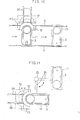
- the coil generally has two poles so that a magnetic flux 113 flows from an electrode 111 to an electrode 112. 114 denotes an iron core and 115 denotes a winding coil. An eddy current generated by the shifting field is caused in the direction perpendicular to the paper surface. Then, on the molten steel 106, a force 118 in the horizontal direction, which is directed in the shifting direction of the shifting field and a depression force 119 in a direction perpendicular to the shifting direction are exerted.
- the component of magnetic flux density for generating the force 118 in the horizontal direction is the component 120 in the perpendicular direction to the molten steel 106.
- the magnetic flux density component 120 in the perpendicular direction to the molten steel 106.
- the outer shell of the coil device is formed of a metal having small magnetic loss, such as an austenitic stainless steel or so forth, which outer shell is arranged in direct opposition to the molten metal container.
- the coil device has a coil body 151 within a casing 152 as shown in Fig. 57, for example.
- the casing 152 is formed of a metal.
- the eddy current can be generated within the casing member to cause heat generation to create problems of lowering of strength of the casing or burning out of the coil body within the casing.
- the heat radiated from the tundish of the molten metal is directly received by the metal casing of the coil device to cause failure of the coil device.
- the molten metal overflows from the tundish for the molten metal, it may cause a problem of melting off of the coil device.
- a pouring method employing a nozzle submerging the tip end thereof into the molten metal as shown in Fig. 62 is generally employed.
- 181 denotes a molten metal
- 182 denotes a ladle
- 183a denotes a long nozzle
- 184 denotes a tundish
- 186 denotes a submerged nozzle
- 188 denotes an upper lid
- 193 denotes a gate.
- the swirling molten metal forms the concave at the swirl center
- the nozzle is submerged to the swirl center
- the length of the nozzle 183a is excessive in the extent to reach the bottom of the container, it causes increasing of the cost for the refractory and difficulty in maintaining strength.
- the nozzle is submerged at the position offsetting from the swirl center for avoiding the foregoing problem, a possibility of damaging of the nozzle due to rotational force of the molten metal cannot be ignored.
- a seal pipe 194 used for the purpose of protecting the poured molten metal stream from air oxidation generally is provided with a diameter four to five or more times greater than the ladle nozzle in view of reduction of the cross-sectional area due to metal splashing. Therefore, upon replacing of the ladle, a opening to communicate with the atmospheric air becomes large to permit air to be contained within the container. The increased oxygen and nitrogen concentration in the container may encounter a problem of degradation of the quality of the cast block at the non-steady state portion. Also, even at the steady state portion, since there are a lot of portions requiring seal between the ladle and the seal pipe, seal can becomes incomplete even if the inert gas introduction pipe 189 is provided to similarly cause the problem of penetration of the air.
- Fig. 67 an apparatus disclosed in Japanese Unexamined Patent Publication No. 1-278706 is illustrated in Fig. 67, in which the centrifugal force is exerted on the molten steel by applying the horizontal rotational force to the molten steel in the tundish for floating up and separating the foreign matter in the molten steel to the tundish center with the concentric force due to difference of the specific weight.
- the centrifugal force is exerted on the molten steel by applying the horizontal rotational force to the molten steel in the tundish for floating up and separating the foreign matter in the molten steel to the tundish center with the concentric force due to difference of the specific weight.
- the molten metal 207 poured through the nozzle 202 from the ladle 201 to the tundish 203 is generated the horizontal swirl flow 206 by the shifting field generating coil 209 to float up and separate the foreign matter and to extract a purified steel via a tundish nozzle at a position offsetting from the swirl
- the molten steel 207 in the tundish 203 can be provided with a lid thereon for preventing the air from penetrating as much as possible so as to avoid re-oxidation due to contacting with the air and for preventing splashing upon pouring.
- a moving table normally called as a tundish car
- a further object of the invention is to problems set forth above and to provide an apparatus for removing non-metallic foreign matter in a molten metal for effectively and economically realizing separation and removal of the non-metallic foreign matter in the molten metal.
- a still further object of the invention is to solve the foregoing problems and to provide a tundish for continuous casting for efficiently separating a slag in the molten metal of from small size to large size.
- a yet further object of the invention is to solve the foregoing problems and to provide an apparatus for removing non-metallic foreign matter in a molten metal for effectively realizing separation and removal of the foreign matter in the molten steel either at replacing of a ladle or at a steady state.
- a still further object of the invention is to solve the above-mentioned problems and to provide a vibration suppressive tundish for separating and removing non-metallic foreign matter in a molten metal.
- a yet further object of the invention is to provide a non-metallic foreign matter removing apparatus for a molten metal which prevents vertical reversing flow from being generated even when a heating coil is actuated and thus certainly maintain a function for separating the foreign matter.
- a yet further object of the invention to solve the foregoing problems and to provide a tundish which includes a shifting field generating coil device which can avoid oxidation of a molten steel and certainly maintain a foreign matter separating function.
- a yet further object of the invention is to provide a tundish which has a shifting field generating coil device which enhances rotational stirring of a molten steel in the tundish for improving a separation effect of foreign matter in the molten steel.
- a still further object of the invention is solve the above-mentioned problem and to provide a shifting field generating electromagnetic coil device with enhanced heat insulation or refractoriness.
- a yet further object of the invention is to solve the foregoing problems and to provide a shifting field generating coil device which can avoid lowering of performance or burning of the coil.
- a yet further object of the invention is to solve the problem and to provide a non-metallic foreign matter removing apparatus for a molten metal which has a device for promoting heat radiation.
- Another object of the invention is to overcome the problems set forth above and to provide a casting method, in which can restrict non-metallic foreign matter to be introduced into a tundish from a ladle and stably perform casting by employing means for actively promoting separation and removal of the non-metallic foreign matter in the tundish, and whereby obtain high quality cast block.
- a further object of the invention is to solve the foregoing problems and to provide a processing-method of a molten steel in a tundish which can provide proper rotational force at respective operation stage in a molten steel processing in the tundish.
- a tundish apparatus for continuous casting of a steel comprises a tundish having a swirl flow bath and a coil, the coil and the swirl flow bath of the tundish being movable relative to each other for opposing in close proximity to each other.
- the tundish is moved by a traveling or pivoting means.
- the coil is movable by means of a lifting means or by means of a traveling or pivoting means.
- a tundish moving apparatus for continuous casting of a steel comprises a movable base, a tundish mounted at a predetermined position on the movable base and having a swirl flow bath, a coil mounted on the movable base for relative movement for opposing in close proximity to a side wall of the swirl flow bath of the tundish, and a power supply means for the coil.
- the tundish moving apparatus for further comprises a guide for positioning the tundish and the coil at predetermined positions.
- an apparatus for removing a non-metallic foreign matter in a molten metal in which horizontal swirl flow is provided for the molten metal for separating and removing the non-metallic foreign matter in the molten metal, comprises a swirl flow bath receiving the molten metal and flowing the molten metal in horizontal swirl fashion, and a floatation bath provided with a flowing out opening in communication with the swirl flow bath and floating up the non-metallic foreign matter in the molten metal, the swirl flow bath having a dimension satisfying h ⁇ 0.47 x q 1/3 t m ⁇ 2
- a tundish for continuous casting of a molten metal comprises at least a receptacle bath and a swirl flow bath, the molten metal in the swirl flow bath being flown in swirl fashion by a coil, and a partitioning wall having a communication opening at the lower portion thereof being arranged between the receptacle bath and the swirl flow bath.
- a tundish for continuous casting of a molten metal comprises at least a receptacle bath, a swirl flow bath and a flowing out bath, the molten metal in the swirl flow bath being flown in swirl fashion by a coil, the swirl flow bath being provided between the receptacle bath and the flowing out bath, and partitioning walls, each having a communication opening at the lower portion thereof, being arranged between the receptacle bath and the swirl flow bath and between the swirl flow bath and the flowing out bath.
- the flowing out bath preferably has a plurality of discharge openings.
- an apparatus for removing a non-metallic foreign matter in a molten metal for separating and removing the non-metallic foreign matter from the molten metal by providing horizontal swirl flow for the molten metal comprises a swirl flow bath receiving the molten metal and flowing the molten metal in swirl fashion, a floatation bath having flowing out opening in communication with the swirl flow bath and floating up the non-metallic foreign matter in the molten metal, a baffling wall being provided immediately below a partitioning wall separating the swirl flow bath and the floatation bath or projected from the bottom wall at the side of the floatation bath.
- a vibration suppressive tundish assembly has at least a swirl flow bath and flowing a molten metal in the swirl flow bath in swirl fashion by a coil, wherein a member of the swirl flow bath of the tundish in an electromagnetic range applied by the coil is formed of a non-conductive body.
- the member formed of the non-conductive body is preferably reinforced by a reinforcement material.
- the reinforcement material is preferably an iron reinforcement or carbon fiber.
- an apparatus for removing a non-metallic foreign matter in a molten metal comprises a tundish having at least a swirl flow bath for providing horizontal swirl flow for the molten metal to remove the non-metallic foreign matter from the molten metal, and a plurality of channels of shifting field generation coils arranged vertically in opposition to the circumference of the tundish, the upper channel and lower channel coils being variable of frequency and/or current to be applied thereto.
- a tundish assembly comprises a tundish having at least a swirl flow bath for providing horizontal swirl flow for the molten metal to remove the non-metallic foreign matter from the molten metal, a plurality of channels of shifting field generation coils arranged vertically in opposition to the circumference of the tundish, and a control device therefor, current, frequency or polarity to be applied to the coils being variable so that the rotation speed of the molten metal by the upper coil being at least lower than the rotation speed of the molten metal by the lower coil.
- a tundish assembly comprises a tundish having a swirl flow bath and floatation baths at both sides of the swirl flow bath and a coil device arranged in opposition to the outer periphery of the swirl flow bath, the coil device having a plurality of electrodes and arranging the electrodes in positions opposing across the swirl flow bath, and the opposing electrodes being provided different polarities to each other.
- a shifting field generating electromagnetic coil device arranged in opposition to a tundish which has at least a swirl bath for providing horizontal swirl flow for a molten metal for separating and removing a non-metallic foreign matter in the molten metal, wherein an insulating material is provided to the coil device at least on the surface opposing to the tundish.
- a shifting field generating electromagnetic coil device arranged in opposition to a tundish which has at least a swirl bath for providing horizontal swirl flow for a molten metal for separating and removing a non-metallic foreign matter in the molten metal, wherein cooling device is provided in the coil device at least on the inner surface opposing to a molten metal container and/or in the tundish at least on the portion opposing to the coil device.
- the cooling device is preferably a water jacket or a water pipe panel.
- an apparatus for removing a non-metallic foreign matter in a molten metal has a tundish having a swirl flow bath and floatation baths at both sides of the swirl flow bath and a coil device arranged in opposition to the tundish, wherein a cooling device is provided for discharging cooling fluid into a gap between the tundish and the coil device.
- the cooling fluid is preferably the air or air with water mist.
- a casting method of a molten metal for pouring a molten metal from a ladle to a mold via a tundish comprises the steps of: (a) providing horizontal swirl flow for the molten metal in the tundish by a magnetic force, (b) providing a lid having high sealability for the tundish and replacing the interior of the container with an inert gas before casting and during casting; and (c) pouring the molten metal into the tundish from the lower portion of the ladle through a refractory nozzle having a length extending into the interior of the tundish enclosed by the lid and not submerging into the swirling molten metal.
- a processing method for a molten metal in a tundish comprises the steps of forming a concaved surface of the molten metal by rotating stirring employing a shifting field generation coil, while processing the non-metallic foreign matter in the molten metal in the tundish, in which the concaved surface is formed, detecting the height of the concaved surface of the molten metal at the center portion and the outer circumference, calculating the rotation speed of the molten metal based on the detected value, and controlling the rotation speed of the molten metal based on the calculated value.
- Fig. 1 is a diagrammatic illustration diagrammatically showing one embodiment of a continuous casting of a steel, for which one embodiment of a tundish moving apparatus for the steel continuous casting, according to the present invention, is applied.
- a molten steel 2 within the ladle 1 is poured through an air seal pipe 4 into a swirl flow bath 16 in the tundish 3 which has the swirl flow bath 16 and a distribution bath 17.
- a rotational force is applied to the molten steel in the swirl flow bath 16 by means of a rotational force generating apparatus (coil) 12.
- a part of the molten steel circulated therein is transferred to the distribution bath 17 from a flow opening 20 at the bottom of the swirl flow bath 16 and then poured into the mold 8 via a sliding nozzle 6 and an immersion nozzle 7 to be casted in a predetermined dimension.
- Fig. 2 shows a plan view of the tundish 3.
- the molten steel 2 in the ladle 1 is poured through an inlet 18 located substantially at the center of the swirl flow bath 16, and applied the rotational force by the coil 12 to flow in swirl fashion as indicated by an arrow.
- a partitioning wall 19 is provided between the swirl flow bath 16 and the distribution bath 17.
- a part of the molten steel is poured into the mold 8 through a discharge output 21 via a flow opening 20 formed in the partitioning wall 19, and the distribution bath 17.
- the tundish 3 and the coil 12 are separated from each other. At least one of these can move relative to the other.
- a moving means for the tundish 3 and a moving means for the coil 12 are separated to each other so that the tundish 3 and the coil 12 may move independently of the other.
- the tundish 3 and the coil 12 are mounted on a common moving base (for example, tundish car), but separated to each other so that the coil 12 is rigidly secured on the moving base and the tundish 3 is detachable from the moving base to permit relative movement to each other.
- a coil 12 is arranged in the vicinity of a pouring floor, which coil has a moving device 13 enabling movement in back and forth, up and down, and left and right by traveling or pivoting, or is rigidly fixed. By making smaller or eliminating the magnitude of movement of the coil, restriction by the power source cable or so forth can be avoided.
- a driving device tilt driving system
- the coil 12 is shifted to approach to an iron skin of the tundish 3 by the moving device 13.
- the coil 12 is shifted to a predetermined position in the casting position by the moving device 13, and fixed in place and thereafter, the tundish is moved to the fixed coil 12 by the above-mentioned tundish drive system.
- the iron skin of the tundish 3 is approached.
- the power source for the coil and the cooling water have to follow. This can be accomplished by installing a supply device (for example, a cable bearer including a coil power source cable and a cooling water cable and so forth as illustrated by represented by the reference numeral 32 of Fig. 7) provided with expanding and contracting function or rotating function.
- the tundish can be moved by the tundish drive system without interference with the coil. Even in case that the coil interferes the movement of the tundish, it is possible to temporarily shift the coil away from the tundish in advance of moving the tundish in traveling or rotating by the tundish driving system.
- the coil is applied to the tundish only at the casting position. Namely, since the coil is only required to be attached or detached by the coil moving device, it becomes possible to perform operation with at minimum one coil which have been required in the corresponding number to the tundish in the prior art.
- the tundish drive system employed in the present invention is not particularly specified, and it is possible to form the tundish driving system for moving the tundish 3 with a railway (tundish car rail) 9, on which a tundish moving carriage 11 is mounted and is driven by a not shown driving power source, such as a motor, to travel, as shown in Fig. 9.
- a not shown driving power source such as a motor
- the tundish moving carriage 11 such as that illustrated in Fig. 7 does not require to mount the coil 12, it can be smaller than the tundish moving carriage 11 illustrated in Fig. 18.
- tundish driving system driving systems which drives for lateral travelling, driving systems which drives for elevating up and down and so forth may be employed.
- the tundish driving system which permits fine adjustment of the distance between the coil 12 and the tundish 13 is preferred.
- coil moving device 13 which is the most particular coil moving means of the shown aspect.
- the coil 12 is moved (lifted) in vertical direction to approach to the iron skin of the tundish 3.
- the coil 12 is approached to the iron skin by horizontal movement, such as traveling or pivoting.
- a mechanisms for generally moving heavy weight articles such as a hydraulic device, screw jack and so forth can be employed, and thus is not particularly specified.
- the utilities, such as water, power source cable, air and so forth may be coupled through coupling means (for example, the coil power source cable as represented by the reference numeral 32 in Fig. 7), such as cable bearer, rotary joint, slip ring or so forth.
- Figs. 5 and 6 show one practical embodiment of the present invention.
- the apparatus according to the present invention as illustrated in Figs. 5 and 6 is designed to move the tundish 3 by a pivoting means, and to move the coil 12 by an lifting means.
- Fig. 5 there is illustrated an example, in which the turret type tundish transporting platform moving the tundish 3 with the pivoting means is employed as the tundish driving system.
- a tundish turret 23 is provided at a pivoting center 22a.
- the tundish 3 is supported on an arm 24 of the tundish turret so that the arm 24 is pivoted about the pivoting center shaft 22 to move at a predetermined position within a path 26 of the tundish.
- the reference numeral 25 denotes a hunger for the tundish 3
- the reference numeral 28 denotes a pivoting center of the ladle 1
- the reference numeral 29 denotes a swing tower of the ladle 1.
- a lifting base (coil base) 27 is provided below the tundish 3.
- a vertical drive device 30 is attached below the lifting base 27.
- the coil 12 is fixedly mounted on the lifting base 27 so that it may be approached for applying the magnetic field to the molten steel in casting, by operation of the known hydraulic cylinder or so forth.
- the tundish drive system has been omitted from illustration. Since the coil 12 is lowered in conjunction with lowering of the lifting base 27, the tundish 3 can be pivoted without causing interference.
- FIG. 7 there is shown a sectional diagrammatic illustration of another embodiment of the apparatus according to the present invention, in which the tundish 3 is moved by a traveling means and the coil 12 is moved by the lifting means.
- the coil 12 is mounted on a coil carriage 10 and lifted up and down by a hydraulic cylinder 31.
- wheels 34 for smoothly moving the carriage 10 along the inner peripheral surface 33 are mounted.
- a coil power source cable 32 for connecting the coil 12 to the power source is connected via the carriage 10.
- the cable 32 has sufficient length for permitting up and down motion of the carriage 10. At the lowered position of the carriage, it may be suspended in the U-shaped fashion.
- the utilities, such as water, air and so forth necessary for the coil 12 are also attached to the coil 12 via the carriage 10 in vertically movable fashion by known means similarly to the cable 32.
- the tundish 3 is constructed to mounted on a tundish carriage (tundish moving carriage) 11 which has wheels 34 to travel on a not shown railway (tundish rail).
- the mold is omitted from illustration.
- Fig. 8 is a perspective view showing a further embodiment of the apparatus according to the present invention, in which the tundish 3 is moved by a pivoting means and the coil 12 is moved by a pivotally traveling means.
- the tundish 3 is mounted on the arm 24 of the tundish turret 23 so as to be pivotally moved about the pivoting center shaft 22,
- the coil 12 is fixedly mounted on a coil carriage 10 which has wheels 34 so as to be moved by traveling on a railway (coil car rail) about a pivoting shaft 35.
- the coil 12 can be approached to the iron skin of the tundish by pivotal movement by the carriage 10.
- the moving means of the tundish 3 and the coil 12 can be a traveling means, such as a railway traveling type or so forth, a pivoting means, such as the turret type or so forth, or a lifting means, or, in the alternative, of any combination of the foregoing means.
- the present invention may include the construction, in which the coil 12 is fixed at the position where the mold 8 is arranged, and the coil 12 and the swirl flow bath 16 of the tundish 3 are placed in opposition in close proximity by the moving means of the tundish 3. Since the energization coil 12 can be shifted away relative to the tundish 3 without conflicting with the tundish 3 upon replacing new and old tundishes 3, only one energization coil 12 is required. Also, the tundish carriage (turret arm) 11 can be small one.
- each embodiment it may be possible to position the coil 12 opposing to the swirl flow bath 16 of the tundish in the close proximity thereto by moving the coil with the coil moving means, after positioning the tundish 3. Conversely, it is also possible to initially position the coil 12 and to subsequently position the tundish.
- Figs. 9(a) and 9(b) it is possible to attach and detach the coil 12 by driving the tundish carriage 11 mounting the tundish 3 on a rail 9 (traveling railway) and pivoting the coil 12 with an arm 37 about the pivoting shaft 35, so that the coil is opposed to the iron skin in the close proximity thereof.
- the tundish carriage 11 travels in a shorter axis direction perpendicular to the longitudinal axis direction on the rail 9 with not shown wheels mounted in the vicinity of both of the longitudinal ends of the tundish.
- the tundish carriage 11 mounting the tundish 3 travels on the rail 9 in the direction perpendicular to the longitudinal direction thereof, and, the coil carriage 10 mounting the coil 11 travels on the rail 36 in the longitudinal direction of the tundish 3.
- the rail 9 to travel the tundish carriage 11 has to be branched into two directions at the terminating end so as to enable setting there to and shifting away therefrom.
- the coil 12 is not necessary to cover the semi-cylindrical iron skin of the swirl flow bath 16 of the tundish and can be of any configurations which permit to be placed at the side of the swirl flow bath in opposition to the iron skin in the close proximity thereto for applying the rotational force for the molten steel in the tundish 3.
- the coil can be in the separated form, or a different type of coil. For instance, a superconducting coil and so forth can be suitably employed.
- the tundish 3 is mounted on a movable base driven to travel on a rail 9 by a drive device 38, such as a motor or so forth.
- the movable base can be a tundish mounting base 39 on the tundish car 11.
- the tundish mounting base may comprise a worm jack device for lifting the tundish, for example.
- the tundish mounting base is adapted to move the tundish 3 to the position above the mold 8 from the mounting position with maintaining the tundish 3 in a position mounted on the tundish car 11.
- the tundish is mounted on the mounting base 39 by means of a crane, and the mounting base is lifted down after moving the moving base at a position above the mold. It is also possible to use a part of the tundish car 11 common to the tundish mounting base and to mount the tundish at the position above the mold.
- a coil 12 is preliminarily mounted at a position opposing to the side wall of the swirl flow bath 16 so that part of or all of the molten steel in the swirl flow bath 16 of the tundish can flow in swirl fashion.
- a water cooling cable 37 is connected via a table bearer 15.
- the tundish 3 and the coil 12 are separated completely, it is not necessary to detach the coil 12 at every occurrence of replacing of the tundish 3.
- a guide 40 as shown in Figs. 16 and 17, may be provided for facilitating positioning upon mounting the tundish 3 onto the tundish car 11 so that the tundish 3 can be quickly and certainly attached and detached by hanging down or hanging up the tundish with the crane or so forth along the guide 40.
- 40a denotes a guides at the side of the tundish.
- the period required for replacing tundish 3 can be shortened for about 50 minutes in comparison with the case where the coil 12 is fixed with the tundish 3 as in the prior art.
- the major factor for this resides on connecting operation of the cable 32.
- the cable 32 can be connected to the coil 12 through a cable bearer 15 upon preliminarily fixing the coil 12 on the tundish car 11, it is advantageous to only require replacing operation of the tundish 3.
- the maintenance capability of the tundish 3 can be improved. Namely, the tundish 3 has to be replaced with the repaired tundish after several charges or several tens charges at the longest, due to melting of a lining brick or so forth. At this occasion, if the tundish 3 is handled in the position where the coil 12 is attached thereto, the following problems should be encountered.
- an accurate positioning of the relative position of the coil 12 and the tundish 3 can be achieved by providing the guide 40 directly on the moving base 11 or via the tundish mounting base in order to certainly determine the relative position between the coil 12 and the tundish 3.
- the first aspect of the invention is constructed as set forth above, it is suitable for the tundish having the swirl flow bath for swirling the molten steel and enables operation with replacing and repairing of the tundish.
- frequency of connecting operation for the cable, water, air and so forth is lowered so that the connecting operation becomes unnecessary except for the case where the cable per se is to be repaired.
- this type of the tundish becomes possible to be practically used.
- the present invention it is possible to provide rotating force for the tundish during casting, and to temporarily shift the coil away from the tundish when the tundish is moved by pivoting or traveling.
- the coil is applied to the tundish only at the casting position. Therefore, casting operation can be performed with one coil at minimum while corresponding number of coils to the number of tundishes have been required in the prior art.
- the tundish and the coil are approached only at necessary position and only at necessary timing, it becomes very easy to move to the positions other than the casting position upon replacing of the tundish or repairing of lining of the tundish and can be operated in the equivalent manner to the tundishes having no coil.
- the second aspect of the invention is constructed as set forth above, the following effects can be achieved by fixing the coil which provides swirl flow for the molten steel, on the moving base and enabling to travel with the tundish.
- the apparatus for removing the non-metallic foreign matter in the molten steel comprises separately constructed tundish and the coil. Therefore, discussion will be given, at first, for designing and construction of the tundish and then for the coil.
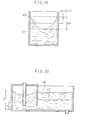
- An apparatus (tundish) 50 for removing the non-metallic foreign matter in the molten metal includes a swirl flow bath 41 and a floatation bath 42.
- the molten steel is poured from the ladle (not shown) though a nozzle 43 as indicated by an arrow in Fig. 19.
- the poured molten steel is preferably flown in the horizontal swirl fashion by a rotating or shifting field generating device 44.
- the molten steel thus purified flows into the floatation bath 42 through a communication opening 45 at the bottom of the swirl flow bath 41.
- the residual non-metallic foreign matter in the statically placed molten steel floats up in the floatation bath 42 and is thus separated.
- the molten steel thus further purified is poured into the mold (not shown) via a discharge output 46 and produced as a casted product.
- the necessary maximum molten steel level H (see Fig. 20) in the swirl flow bath while the molten steel is steadily flowing in and out, becomes the height of the sum of the minimum molten steel level, the proturburance height of the molten steel surface and the level lowering magnitude during ladle replacement and can be expressed by the following equation.
- 47 denotes the molten steel level in the floatation bath corresponding to the minimum molten steel level in the swirl flow bath
- 48 denotes a molten steel level corresponding to the maximum molten steel level in the swirl flow bath.
- H q x t c ⁇ (a x b + ⁇ x r 2 ) + (r x ⁇ ) 2 4g + q x t m ⁇ x ⁇ x r 2
- the necessary minimum average dwell period in the swirl flow bath and the necessary minimum molten steel level necessary for achieving foreign matter separating and removing effect by the horizontal rotation are obtained through a water model experiments.
- the necessary minimum average dwell period t m is 2 min irrespective of the molten steel flowing out velocity
- the range of radius of the swirl flow bath satisfying the minimum molten steel level required in the non-steady state, such as ladle replacement and so forth is determined by the equation (3).
- the apparatus for effectively removing the non-metallic foreign matter which can be a cause for defects in the products, such as sheet can be formed without excessive enlarging of the facility. Furthermore, by employing the apparatus, the non-metallic foreign matter can be steadily removed even in the non-steady state, such as during ladle replacement and so forth to lower the fault ratio of the product and to enable substantial improvement of the yield.
- Figs. 24 and 25 shows another embodiment of a tundish for continuous casting of the molten metal, according to the present invention.
- a tundish 54 has a swirl flow bath 54a partitioned by a wall 56.
- a ladle nozzle 53 extending from the bottom of a ladle 52 is inserted into a receptacle bath 54b which is positioned right side of the wall 56 seeing in Fig. 25.
- An opening 54d for communicating the receptacle bath 54b and the swirl flow bath 54a is defined below the wall 56.
- a rotating field generation coil 55 is arranged.
- a tundish nozzle 58 is provided at the bottom of the swirl flow bath 54a so that the molten metal is poured into a mold 59 arranged therebelow.
- a sliding gate or a stopper for controlling the molten metal flowing out amount is provided in the tundish nozzle 58.
- Figs. 26 and 27 shows one embodiment of the tundish for continuous casting of the molten metal according to the second invention.
- the tundish 54 has the swirl flow bath 54a defined by walls 56 and 57 at the center thereof.
- a ladle nozzle 53 extending from the bottom of a ladle 52 is inserted into a receptacle bath 54b which is positioned right side of the wall 56 seeing in Fig. 27.
- An opening 54d for communicating the receptacle bath 54b and the swirl flow bath 54a is defined below the wall 56.
- a rotating field generation coil 55 is arranged.
- a flowing out bath 54c communicating with the swirl flow bath 54a via an opening 54e is provided at the left side of the wall 57.
- a tundish nozzle 58 is provided in the flowing out bath 54c so that the molten metal is poured into a mold 59 arranged therebelow.
- 65 denotes a stopper for controlling molten metal flowing out amount through the tundish nozzle 58.
- the present invention is applicable for continuous casting multi-stranders. Namely, in case of the multi-siranders, it have been generally required rotating field generation devices (coils) in the corresponding number to the stranders. However, it becomes possible to place the coil at one position. Figs.28 and 29 show the example thereof.
- a distribution bath 54f of substantially rectangular configuration is provided in place of the above-mentioned flowing out bath at a position perpendicular to the receptacle bath 54 and the swirl flow bath 54a.
- a plurality of flowing out openings 64 are provided at the bottom of the distribution bath 54f.
- the coil 55 is required to be placed at one position.
- 63 is an induction opening of the molten metal poured from the ladle (not shown).
- the distribution bath is provided on the extension of the receptacle bath 54b and the swirl flow bath 54a.
- the coil is required to be placed at only one position.
- the molten metal 51 is poured into the receptacle bath 54b of the tundish 54 via the ladle nozzle 53 from the ladle 52.
- the molten metal does not flow in swirl fashion. Therefore, melting of the ladle nozzle due to flow velocity can be significantly decreased and breaking of the nozzle will never been caused.
- the slag can be separated in the swirl flow bath as the next bath.
- the received molten metal 51 passes through the opening 54d through the wall 56.
- the molten metal in the swirl flow bath 54a is flown in horizontal swirl fashion.
- the molten metal purified by separating the slag 62 reaches the flowing out bath 54c through the opening 54e of the wall 57.
- the molten metal then reaches the tundish nozzle 58 after naturally floating the residual non-metallic foreign matter in the flowing out bath 54c.
- variation of the molten metal surface due to flow velocity of the molten metal 61 in the swirl flow bath 54a rotated by the rotating field generation coil 55 is restricted by the walls 56 and 57. Also, it can prevent the slag separated and floating from flowing out to the downstream side.
- the casting with high quality can be done efficiently by providing the swirl flow bath separated from the receptacle bath of the molten metal by the wall, in the tundish, generating the horizontal swirl flow in the swirl flow bath and thus performing slag separation.
- An apparatus (tundish) 80 for removing the foreign matter in the molten steel has the swirl flow bath 71 and a floatation bath 72.
- the molten steel 77 is poured to the swirl flow bath 71 as illustrated by an arrow in Fig. 37 through a nozzle 73 from the ladle (not shown).
- the poured molten steel is preferably flown in swirl fashion in the horizontal direction as illustrated by an arrow in Fig. 36 by a rotating or shifting field generation device (hereafter referred to as coil) 74.
- coil rotating or shifting field generation device
- the molten steel stays in the swirl flow bath 71 over a certain period and then flows into the floatation bath 72 through a communication opening 75 provided in a partitioning wall 78. Most of the foreign matter is aggregated and separated in the swirl flow bath 71. The remainder can be almost completely floated in the floatation bath 72. Subsequently, the molten steel is introduced into the mold (not shown) via a flowing out opening 76.
- the communication opening 75 for communication from the swirl flow bath 71 to the floatation bath 72 there is shown an example, in which the communication opening is shown at a position on a line extending through the induction opening 73 and the flowing out opening 76. However, the position is not specified to that illustrated.
- a horizontal distance between the baffling wall 78a and 78 is desired to be approximately 300 mm.
- the present invention provides the buffer function of the molten metal in the non-steady state, such as ladle replacement or so forth, by separating the swirl flow bath 71 and the floatation bath 72 without increasing the dimension of the rotating portion. Also, by certainly providing floating period, the enhanced foreign matter separation effect can be achieved. Furthermore, by specifying the position of the communication opening 75 between the swirl flow bath 71 and the floatation bath 72, flowing out of the foreign matter by short circuit can be prevented to further ensure the foreign matter separation effect.
- the molten steel purified in the swirl flow bath 71 flows into the floatation bath 72 through the communication opening 75 from the swirl flow bath 71 and statically placed therein so that the residual foreign matter will float up and separated in the floatation bath 72.
- the molten steel thus further purified is poured into the mold (not shown) to be formed into the casted product via the flowing out opening 76.
- the apparatus for effectively removing the foreign matter which can be a cause of defect in the product, such as a sheet without excessively increasing the size of the facility.
- the steady foreign matter removing effect can be obtained even at the non-steady state, such as during ladle replacement to lower fault ratio of the product and thus significantly improve the yield.
- the highly purified steel can be obtained without no substantial equipment investment and thus at low cost.
- the molten metal in the ladle is poured in a swirl flow bath 83 of a tundish 90 having the swirl flow bath 83 and a distribution bath 84 as shown in Fig. 41.
- a rotational force is applied to the molten metal in the swirl flow bath 83 by a shifting field generating electromagnetic coil 85 to flow in the swirl fashion.
- a portion of the molten metal is transferred from the bottom portion of the swirl flow bath 83 to the distribution bath 84 and then poured into the mold through the bottom portion of the tundish 90 to be cased into a predetermined dimension.
- 82 denotes an iron skin
- 88 denotes a refractory material.
- the non-metallic foreign matter is separated from the molten metal in the swirl flow bath 83, and the purified molten metal is poured into the mold via the distribution bath 84.
- the present invention forms the container portion of the tundish in the region placed vithin the magnetic field of the coil 85, of a non-conductive body.
- a force is generated by co-action of a magnetic field generated by an eddy current and the shifting field.
- the member of the non-conductive body container portion 81 of the tundish to be placed within the shifting field is formed of the electrically non-conductive body, such as ceramic or so forth, the eddy current will never been produced and thus the force will not be generated. Therefore, unnecessary force will not be generated in the tundish 90 by the shifting field in the electromagnetic field range applied by the coil 85 to suppress vibration and whereby to make metering of the molten steel in the tundish stable. Also, since the stabilization of the flow at the surface of the molten steel can be promoted to allow avoidance of the penetration of the impurity, such as the non-metallic foreign matter to achieve stable casting operation and production of high steel quality.
- Figs. 41 and 43 show another construction of the non-conductive body container portion 81 of the tundish 90.
- metallic wires are used in the non-conductive body container portion 81 for the purpose of reinforcement, magnitude of the eddy current is minimized by arranging the vertical metal wires 86 and the lateral metal wires 87 with avoiding electrical contact between the reinforcement wires, suppression of the vibration force is enabled.
- the reinforcement material 86 and 87 an iron reinforcement, carbon fiber are preferred. However, it can be an engineering plastics.
- the coil device is an electromagnetic coil device which is generally used and generates shifting field, and can be a coil for a linear motor.
- the present invention is constructed as set forth above, by forming the member of the swirl flow bath of the tundish to be placed within the electromagnetic field applied by the coil, with the non-conductive body, unnecessary force will not be created in the tundish to provide effect of suppression of vibration. Also, with this, stable operation and product quality can be obtained.
- a molten steel 94 in the ladle is poured into the tundish 91.
- the tundish 91 rotational force and heat is provided for the molten steel 94 in the tundish 91 by switching of the frequency of the shifting field generation coil 93 so as to promote floating and separation of the non-metallic foreign matter.
- the molten metal 94 flown in the swirl fashion is poured into the mold via a nozzle 97 provided at a position of the bottom portion of the tundish 91 offsetting from the rotation center and casted into a predetermined dimension.
- the non-metallic foreign matter is separated from the molten steel 94 in the tundish and the purified molten steel is poured in the mold.
- the present invention can generate necessary horizontal swirl flow 96 and maintain the desired molten steel temperature for the molten steel 94 in the tundish 91 by providing a plurality of channels of coils 93 which are arranged vertically on the outer periphery of the tundish and independent of each other (in Fig. 44, upper and lower two channels of coils 93 are provided). At this time, even when both of the upper and lower coils 3 are actuated simultaneously, a vertical reversing flow by heating will never be generated.
- the frequency of the coil for heating is desirably 50 to 100 Hz
- the frequency of the coil for rotating is desirably 0.5 to 10 Hz.
- the lower channel coil may be switched to operate for heating.
- the coil condition can be varied in such a manner that, in case of the frequency, switching is made between heating and rotation speed, and in case of the current, the intensity of the magnetic field is varied, heating of the molten steel and the rotating stirring of the molten steel in the swirl flow bath can be freely controlled.
- the molten metal to which the present invention is applied is not specified to the molten steel. Also, with respect to the tundish, the configuration should not be specified as long as it has at least the swirl flow bath.
- a plurality of channels of shifting field generation coils 93 are arranged in the vertical direction of the swirl flow bath of the tundish so that one of the coils is used as a coil primarily for rotating stirring and the other of the coils is used as a coil primarily for heating to apply the frequency suitable for heating the molten steel.
- the vertical reversing flow 95 to be generated by the conventional heating coil can be eliminated. Therefore, with maintaining the foreign matter separating function by the rotating stirring flow 96, temperature drop of the molten steel 94 can be certainly prevented by heating.
- the non-metallic foreign matter is separated from the molten steel 106 in the tundish 110, and purified molten steel is poured into the mold.
- the present invention includes a plurality of channels of the mutually independent shifting field generation coils, e.g. coils 101a and 101b, arranged vertically on the outer periphery of the tundish 110.
- necessary horizontal swirl flow 109 can be induced in the molten steel 106 in the tundish, and can maintain the thin depth of the concaved surface on the molten steel surface (Fig, 47 shows upper and lower two channels of coils 101a and 101b).
- the upper and lower coils 101a and 101b can be actuated simultaneously, or one of those can be actuated depending upon the necessity.
- the coils 101a and 101b are adjusted the current and the frequency, or the polarity to be applied to the coils by an appropriate control device (not shown) in such a manner that the flow velocity of swirl flow 109a of the molten steel induced by the coil 101a is lower than the flow velocity of the swirl flow 109b induced by the coil 101b.
- the control device may be a power source device comprising a thyristor invertor or a cycloconverter, for example.
- the coil in the upper channel and the lower channel it can be three, four or more.
- the coil current, frequency or polarity may be modified so that the flow velocity of the swirl flow is gradually lowered from the lower coil to the upper coil.
- Modification of the coil condition is adapted to modify the magnetic field intensity in case of the current, the rotation in case of the frequency and generation of the shifting field in case of the polarity, rotating stirring and the concave depth of the surface of the molten steel in the swirl flow bath can be freely controlled.
- the molten metal, to which the present invention is applied is not specified to the molten steel. Also, with respect to the tundish, the configuration is not specified as long as the at least the swirl flow bath is provided.
- the shifting field generation coils 109a and 109b are provided at the upper and lower portions of the swirl flow bath 110a of the tundish 110, to permit independent control of the swirling velocity in the height direction of the molten steel, the concave depth (Z) due to swirl flow can be reduced at the upper phase of the molten steel. Therefore, a submerged nozzle 107 for pouring the molten steel 106 from the ladle 105 may be required to have the length substantially equivalent to that in the conventional one which is adapted for the case where the molten steel is not flown in the swirl fashion. Therefore, increasing of cost for the nozzle and frequency of the breakage of the nozzle can be avoided.
- the area of the molten steel surface can be maintained to be equivalent to the conventional level, it becomes possible to maintain the oxidation of the molten steel in the level equivalent to the conventional level. Furthermore, at the lower phase of the molten steel, sufficiently high swirling velocity for ensuring the foreign matter separation function can be obtained.
- the present invention provides the upper and lower shifting field generation coil to enable independent control of the flow velocities of the swirl flow at upper and lower regions in the height direction of the molten metal, in the tundish, the length of the submerged nozzle can be shorter in comparison with the conventional case where only one shifting magnetic field coil is employed for inducting the swirl flow. Also, it enables minimize oxidation of the molten metal and certainly provide the foreign matter separating function.
- the coil device is separated into a pair by the floatation baths at both sides of the tundish.
- the tundish has a central swirl flow bath 110a and floatation baths 110b at both sides thereof, as shown in Fig. 51. Since the outer periphery of the swirl flow bath 110a is separated by the floatation baths 110b at both sides, the coil device also becomes the pair of 101c and 101d.
- Each coil device 101c and 101d is formed by arranging the winding coils 115 on an arc-shaped iron core 114. Number of the coils 115 in the coil devices 101a and 101b becomes equal to each other when the floatation baths 110b are aligned on a line extending trough the swirl center 129 of the molten steel in the swirl flow bath 110a, as shown in Fig. 51. Also, respective of the winding coils 115 are arranged in substantially symmetric positions with respect to the swirl center of the molten steel in the swirl flow bath 110a.
- the electrodes forming the coil devices 101c and 101d are arranged as A 1 , B 1 , C 1 , D 1 , E 1 and F 1 , and A 2 , B 2 , C 2 , D 2 , E 2 and F 2 and the coil winding direction or the current to be charged are differentiated so that the polarity of respective symmetric position may be different from each other (for example, when A 1 has N pole, A 2 becomes S pole).
- a magnetic flux also act on the swirl center 129 of the molten steel in the swirl flow bath 110a so as to increase the density of the magnetic flux for generating the rotational force in the molten steel and whereby to obtain large rotational force.
- a magnetic flux 113 directed to the electrode D 1 and a magnetic flux 113a directed to the symmetric pole A 2 across the swirl center 129 of the molten steel are generated.
- molten metal in the present invention is not specified to the molten steel.
- the present invention is constructed as set forth above, rotating stirring of the molten metal in the tundish can be strengthened and thus the foreign matter separation effect can be enhanced so that good quality of cast block can be obtained.
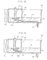
- a molten metal 136 in the ladle 135 is poured in a swirl flow bath 140a of the tundish 140 which has the swirl flow bath 140a and the floatation bath 140b.
- the rotational force is provided to the molten metal 136 in the swirl flow bath 140a by the shifting field generating electromagnetic coil device 131.
- a part of the molten metal 136 flowing in swirl fashion is transferred to the floatation bath 140b from the bottom portion of the swirl flow bath 140a, and then poured in the mold through a sliding nozzle 137 and a immersion nozzle 138 provided through the bottom of the tundish 140 to be casted in a predetermined dimension.
- 133 denotes an iron skin
- 134 denotes a refractory material.
- the non-metallic foreign matter is separated from the molten metal 136 in the swirl flow bath 140a, and the purified molten metal is poured into the mold via the floatation bath 140b.
- the present invention is directed to the coil device 131 arranged in opposition to the swirl flow bath 140a of the tundish 140, and has a heat insulation material 132 on the outer surface of the coil device 131 opposing to the swirl flow bath 140a of the tundish 140.
- the material which can withstand the radiation heat temperature from the tundish such as a refractory, can be used.
- Al 2 O 3 type castable refractory and so forth can be used, and the thickness may be approximately 10 to 50 mm.
- the heat insulation material 132 on the outer surface of the coil 131 at the position opposing to the outer periphery molten metal container and the upper surface thereof.
- the heat insulating material 132 is provided on the portion of the coil device opposing to the molten metal container, i.e. tundish 140, the radiated heat from the molten metal container 140 will never been transmitted directly to the electromagnetic coil for avoiding failure of the electromagnetic coil.
- the surface of conductive wires of the coil is covered with an insulation material.
- the insulation material can cause fatigue to result in shorting. Accordingly, it is desirable to maintain the temperature of the coil device lower than or equal to 170 °C. Also, even when molten metal overflows from the molten metal container, it may not directly contact with the electromagnetic coil to avoid failure of the electromagnetic coil due to melting.
- molten metal of the present invention is not particularly specified, and can be the steel, for example.
- the coil device is a generally used electromagnetic coil device for generating the shifting field, and can be a coil for a linear motor.
- the present invention is constructed as set forth above, and since the heat insulating material is provided on the electromagnetic coil for generating the shifting field to create the horizontal swirl flow in the molten metal, at the portion opposing to the molten metal container, the radiation heat from the molten metal container can be shut off. Also, the leaking molten steel will never contact with the electromagnetic coil. Therefore, the performance of the electromagnetic coil can be steadily maintained.
- a molten metal 136 in the ladle 145 is poured in a swirl flow bath 150a of the tundish 150 which has the swirl flow bath 150a and the floatation bath 150b.
- the rotational force is provided to the molten metal 146 in the swirl flow bath 150a by the shifting field generating electromagnetic coil device 141.
- a part of the molten metal 146 flowing in swirl fashion is transferred to the floatation bath 150b from the bottom portion of the swirl flow bath 150a, and then poured in the mold through a sliding nozzle 147 and a immersion nozzle 148 provided through the bottom of the tundish 140 to be casted in a predetermined dimension.
- 143 denotes an iron skin
- 144 denotes a refractory material.
- the non-metallic foreign matter is separated from the molten metal 146 in the swirl flow bath 150a, and the purified molten metal is poured into the mold via the floatation bath 150b.
- the present invention is directed to the coil device 141 arranged in opposition to the swirl flow bath 150a of the tundish 150, and has a cooling device 153 on the inner periphery of a casing 152 of the coil device 141 opposing to the swirl flow bath 150a of the tundish 150.
- a cooling device 156 may be arranged at the portion of the tundish 150 at least opposing to the coil device 141.
- cooling device 153 one which can cool within the casing 152 which is heated by the heat of the iron skin 143 generating the heat by eddy current, can be used.
- the cooling device illustrated in Fig. 58 or 59 can be used.
- the cooling device of Fig. 58 is a generally used water jacket in which the cooling water is introduced from an inlet 154 and discharged from an outlet 155.
- the cooling device of Fig. 59 is a known water tube panel, in which the cooling water is introduced through the inlet 154, passes through a panel form water tube and is discharged through the outlet 155.
- These cooling device 153 is arranged at least in opposition to the swirl flow bath 150a of the tundish 150 on the inner periphery of the casing 152, as shown in Fig. 57.
- molten metal of the present invention is not particularly specified, and can be the steel, for example.
- the coil device is a generally used electromagnetic coil device for generating the shifting field, and can be a coil for a linear motor.
- the present invention is constructed as set forth above, and since the cooling device is provided on inner periphery of the casing of the electromagnetic coil for generating shifting field for inducting horizontal swirl flow in the molten metal, at the portion opposing to the molten metal container, the heat in the casing can be absorbed so that the strength of the casing will not be lowered by the heat and burning of the coil body can be prevented. Therefore, the performance of the electromagnetic coil device can be steadily maintained.
- a molten metal 166 in the ladle 175 is poured in a swirl flow bath 170a of the tundish 170 which has the swirl flow bath 170a and the floatation bath 170b.
- the rotational force is provided to the molten metal 166 in the swirl flow bath 170a by the shifting field generating electromagnetic coil device 161.
- a part of the molten metal 166 flowing in swirl fashion is transferred to the floatation bath 170b from the bottom portion of the swirl flow bath 170a, and then poured in the mold through a sliding nozzle 167 and a immersion nozzle 168 provided through the bottom of the tundish 140 to be casted in a predetermined dimension.
- 163 denotes an iron skin
- 164 denotes a refractory material.
- the non-metallic foreign matter is separated from the molten metal 166 in the swirl flow bath 170a, and the purified molten metal is poured into the mold via the floatation bath 170b.
- the present invention includes a cooling device 162 for discharging a cooling fluid through a gap between the swirl flow bath 170a of the tundish 170 and the coil device 161 arranged in opposition to the former.
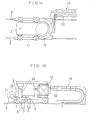
- cooling device 162 may be constructed as shown in Fig. 61, for example but not limitative, with a fluid injecting nozzle header 162a provided along the lower end of the side surface of the coil device 161 opposing to the tundish 170, which nozzle header directs nozzle holes 162b upwardly.
- a fluid such as an air
- a fluid is supplied to be discharged through the nozzle holes 162b to cool the outer peripheries of the iron skin 163 of the tundish 170 and the coil device 161.
- the surface of conductive wires of the coil is covered with an insulation material. When the temperature of the coil is risen, the insulation material can cause fatigue to result in shorting. Accordingly, it is desirable to maintain the temperature of the coil device lower than or equal to 170 °C.
- the flow velocity of the fluid may be selected depending upon the degree of rising of the temperature at the outer peripheries of the iron skin 163 and the coil device 161 and the degree of heat resistances thereof, and may be approximately 10 m/s when the air is used.
- the coil device is a generally used electromagnetic coil device for generating the shifting field, and can be a coil for a linear motor.
- the present invention is constructed as set forth above, and since the cooling fluid is discharged through the gap between the molten metal container, in which the horizontal swirl flow of the molten metal is generated by the shifting field, and the electromagnetic coil device, the heat will not be transmitted to the electromagnetic coil from the molten metal container. Therefore, lowering of the performance or failure of the electromagnetic coil can be eliminated. Also, the temperature of the molten metal container member will not be risen so as to avoid lowering of the strength thereof.
- a molten metal 184 is poured into a tundish 184 through a semi-long nozzle 183 from a ladle 182.
- the molten metal 191 flows in horizontal swirl fashion by a magnetic field generated by a coil 185.
- a submerged type nozzle 183a as shown in Fig. 62 has been used.
- Such type of nozzles tends to cause a trouble in breakage due to rotational force of the molten metal, as set forth above. Therefore, by employing a non-submerged type semi-long nozzle 183, such trouble can be completely avoided.
- the size of the nozzle can be reduced, or also becomes possible to reduce the cost for refractory.
- the present invention achieves the following effect in the casting of the molten metal pouring the molten metal from the ladle to the mold via the tundish,
- the method of the present invention permits the tundish in small size, it may provide an effect in combination with the reduction of the size of the nozzle to lowering of the cost for refractory.
- the rotational force is provided to the molten metal 297 in the tundish 203 by the shifting field generating electromagnetic coil 209.
- a part of the molten metal 207 flowing in swirl fashion is poured in the mold through a nozzle 208 provided through the bottom of the tundish 203 to be casted in a predetermined dimension.
- the non-metallic foreign matter is separated from the molten metal 207 in the tundish 203, and the purified molten metal is poured into the mold.
- Sensors 211 and 212 for detecting distance to the molten steel surface are provided above the swirl center and the outer peripheral edge of the molten steel in the tundish 203.
- the rotation speed N (r.p.m.) can be calculated.
- a microwave level gauges can be employed as the sensors 211 and 212.
- a method for controlling the rotation force there is a method, in which a controller 213 and a setting device 214 are employed; a pattern appropriate rotation speeds at respective stages of operation based on the operational experience is preliminary input to the setting device 214; the rotation speed N is calculated by inputting the signals from the sensors 211 and 212 to the controller 213 and compared with the output signal from the setting device 214; and a power source device 210 is controlled on the basis of the result.
- the molten steel when the molten steel is poured into the swirl flow phase in the tundish from the nozzle of the ladle, it can be poured to the swirl center of the swirl flow phase or at a desired position offset from swirl center. Also, the nozzle of the ladle may be submerged or not submerged into the swirl flow phase in the tundish.
- the tundish moving apparatus as illustrated in Figs. 5 and 6 was employed. Initially, the tundish 3 was positioned, and then the coil 12 is positioned in opposition at close proximity to the former. Then, continuous 10 charges of pouring of the molten steel (tin plate material) was performed for the same tundish 3, and then the tundish 3 was replaced. In this replacement, no abnormality was caused on the coil.
- the replacing operation which conventionally took 80 minutes, could be completed in 30 minutes. Therefore, the period for the replacing operation can be shorted for approximately 50 minutes. In the foregoing embodiment, the similar effect could be obtained even when the coil 12 is initially positioned and the tundish 3 is positioned thereafter.
- the period for the tundish replacing operation can be shorted for approximately 50 minutes in comparison with the tundish operation in the conventional tundish 3 mounted thereon the coil 12.
- the primary factor of this resides on connecting operation of the cable.
- the coil For absorbing heat of the coil due to Juele heat, the coil is cooled by the water.
- the cable does not have sufficient flexibility. Therefore, the cable connecting operation has been considered as lead load work. Accordingly, when the coil is moved according to the present invention, since the cable can be connected through the cable bearer, it can provide an advantage that the replacement of only the tundish 3 body is required.
- tundish 3 is required to be replaced with a repaired tundish due to melting of the lining brick or so forth after several charged or several tens charged at the longest.
- the tundish replacement operation means replacing of the used tundish on the arm 24 with a new tundish. For this, it may be effective to provide two arms 24 and the tundishes are replaced by pivotal motion thereof.
- the second aspect of the tundish moving apparatus as illustrated in Figs. 14 and 15 is employed.
- the continuous 10 charges of pouring of the molten steel (tin plate material) was performed for the same tundish 3, and then the tundish 3 was replaced. In this replacement, no abnormality was caused on the coil.
- the replacing operation which conventionally took 80 minutes, could be completed in 30 minutes. Therefore, the period for the replacing operation can be shorted for approximately 50 minutes. It should be noted that the each condition of the moving apparatus was as set out below.
- FIG. 21 One example (invention) of the non-metallic foreign matter removing apparatus having the swirl flow bath of the invention and the floatation bath, which is minimized and optimized from the formulae (1) and (8) in order to satisfy the operating condition shown in table 1, is illustrated in Fig. 21 with a dimensions (unit : mm).
- the height of the facility has to be approximately 400 mm higher than the example of the invention illustrated in Fig. 21.
- Increasing of the height of the tundish causes substantial increase of the cost for facility due to increasing of the height of building.
- it when it is applied to the existing continuous casting facility, it often becomes impossible to realize due to constraint of the facility.
- the radius of the swirl flow bath to minimize the facility when employed, only about 4 tons of molten steel can be obtained to encounter the problem to make it difficult to certainly maintain the molten steel level.
- a result of a magnetic flaw detecting inspection in production for the cold rolled sheet material is shown in Fig. 34.
- the index in the method of the invention is much smaller in than that in the conventional method.
- samples at the same charge was obtained by slime extraction.
- Comparison of the slag amount thereat is shown in Figs. 32 and 33. As can be clear herefrom, the slag amount is reduced in the method of the present invention in comparison with the conventional method and thus can be appreciated that the foreign matter can be effectively floated and separated by the method of the invention.
- the molten steel (tin plate material) was continuously poured to the same tundish for 10 charges.
- the amount of the foreign matter in the molten steel after flowing out from the tundish was very small, i.e. 0.05 mg/kg.
- Tundish Capacity 20t Swirl Flow Bath Radius 1000 mm Refractory 300 mm thick Basic Brick Iron Skin 350 °C Coil Device Linear Type Semi-circular Coil Material of Non-Conductive Body Container Portion Al 2 O 3 , with vertical reinforcement (3 mm diameter) and lateral reinforcement of 3 mm over entire circumference (arranged as shown in Fig. 42)
- the molten steel (tin plate material) was continuously poured for casing a cast block.
- the inner diameter of the tundish 91 was 1m, and the molten steel depth was 1m.
- the vertically arranged two channels of shifting field generation coils 93 are provided on the outer periphery of this tundish.
- the height of each coil was 0.5m.
- tundish 110 Utilizing the tundish 110 illustrated in Fig. 47, molten steel (tin plate material) wad continuously poured to produce a cast product.
- the inner diameter of the swirl flow bath 110a of the tundish 110 was 1m, and the molten steel depth (static molten steel surface) was 1m.
- the upper and lower two channels of shifting filed generation coils 101a and 101b are provided on the outer circumference. Height of each coil was 0.3m and 0.6m. For the upper coil, 200A of current was applied, and for the lower coil, 1000A of current was applied.
- the upper phase molten steel and the lower phase molten steel are rotated respectively at 10 r.p.m. and 60 r.p.m.
- the depth (Z) of the concaved surface of the molten metal surface was 1.4cm which does not require change of the length of the submerged nozzle 107, oxidation of the molten steel surface was the normal level, the foreign matter separation effect was equivalent to the case where 50 r.p.m. of rotation is induced by a single shifting field, and the resultant cast block quality was good.
- the molten steel (tin plate material) was continuously poured to produce a cast block.
- the shifting field generation coil devices 101C and 10d respectively have the 110° of arc angle with respect to the molten steel swirl center 129 in the swirl flow bath 110a and have lm of the inner radius 125 from the molten steel swirl center 129 to the coil devices 101c and 101d, and 1.6m of the outer radius 126, are arranged.
- 3 Hz and 2000A of current was applied for the coil 101c and 101d.
- Each electrodes forming the coil devices 101c and 101d are arranged at substantially symmetric position with respect to the swirl center 129 of the molten steel in the swirl flow bath 110a. Different polarities are provided for these electrodes. When the same polarity is provided for the opposing electrodes, the rotation speed obtained was 10 r.p.m., and whereas 40 r.p.m. was obtained in the example of the present invention. At this time, the foreign matter separating performance was four times of that in the same polarity.
- the length 27 and the width 28 of the floatation bath 110b were 2m and 1m.
- Tundish Capacity 25 tons Swirl Flow Bath Diameter 1000 mm Refractory 25 mm thick alumina type castable refractory Coil Device linear type semi-circular coil Iron Skin 10 mm thick Molten Steel Temperature 1550 °C Heat Insulation Material (Coil Outer Periphery) 20 mm tick alumina type castable refractory Heat Insulation Material (Coil Upper Surface) 20 mm thick alumina type castable refractory
- the temperature at the surface of the coil device 131 opposing to the tundish 140 was maintained at 100 °C, and the operation of the coil device 131 was held stable.
- Tundish Capacity 20 tons Swirl Flow Bath Diameter 1000 mm Refractory 300 mm thick basic flowable refractory Iron Skin 10 mm thick Molten Steel Temperature 1570 °C Coil Device linear type semi-circular coil Heat Insulation Material (Coil Outer Periphery) 25 mm tick alumina type castable refractory Heat Insulation Material (Coil Upper Surface) 20 mm thick alumina type castable refractory Cooling Water Inlet Temperature 20 °C Cooling Water Outlet Temperature 28 °C
- the temperature at the surface of the coil device 141 opposing to the tundish 150 was maintained at 40 °C, and the operation of the coil device 141 was held stable.
- the temperature at the same portion of the coil device 141 was 200 °C.
- the molten steel (tin plate material) was continuously poured for producing a cast block.
- Tundish Capacity 15 tons Swirl Flow Bath Diameter 1000 mm Refractory 300 mm thick basic brick Iron Skin 10 mm thick Molten Steel Temperature 1550 °C Coil Device linear type semi-circular coil Gap between Tundish and Coil Device 70 mm Cooling Fluid and Flow Velocity air, 10 m/s
- the temperature at the surfaces of the coil device 161 opposing to the tundish 170 and the opposing iron skin 163 were maintained respectively at 100 °C and 350 °C.
- the temperature of the iron skin 163 was not risen to permit long duration of use without causing deformation or crack. Also, rising of the temperature of the coil device 161 could be suppressed to allow using for a long period with stable performance.
- SUS 430 of heat size 100t is casted at a rate of 2 t/min into slab of 200 x 1240 mm size in the matter illustrated in Fig. 64.
- the molten steel 181 was poured into the molten steel swirl center in the tundish 184 from the ladle 182 to perform casting.
- the ladle was replaced for continuously perform casting for 300t in total.
- the molten steel was flown in swirl fashion at the speed of approximately 40 to 60 r.p.m.
- the inside of the container was purged by Ar through an induction pipe 189.
- the capacity of the container was about 6t.
- Fig. 65 the results of casting with rotation by the magnet using the conventional method (shown in Fig. 62) and the method employing the seal pipe 194 are also shown as comparative examples.
- a container having a capacity of 12t with double gate and without means for providing no rotational force is used as the tundish.
- the conventional pouring method although the rotational force is applied in the same condition in the tundish. the conventional pouring method is used.
- the pouring position from the ladle to the tundish was the swirl center. It should be noted that the molten steel used in these examples had 35 to 37 ppm of total oxygen upon finishing of ladle refining. It is considered no difference in condition was present.
- microwave level gauges are mounted as sensors 211 and 212 for detecting the distance to the molten metal surface from the upper end of the tundish 203 having an inner diameter of 1m. Assuming respective of detected length are l 1 and l 2 , the depth Z of the concaved surface formed by rotation of the molten steel 207 can be calculated through the equation (1). From Z thus obtained, the rotation speed N of the molten steel 207 can be derived through the equation (2).
- the controller 213 received the signals from the microwave level gauges to calculate the rotation speed (N), and compared the rotation speed with the output signal from the setting device 214, in which an appropriate rotational speed pattern at respective stages of operation obtained or known from the experience of operations is preliminarily set, to control the power source device 210 of the shifting field generation coil 209.
- the tundish is provided with the swirl flow bath and the floatation bath.
- the molten steel is flown in swirl fashion to float up the non-metallic foreign matter to the surface of the molten steel and the floated non-metallic foreign matter is removed.
- the molten steel removed the non-metallic foreign matter flows out to the floatation bath.
- the static flow in the floatation bath the residual non-metallic foreign matter float up.
- the molten steel thus purified is supplied to the mold from the bottom of the floatation bath.
- the tundish and the coil are formed separately to have the construction allowing relative displacement to each other. Therefore, number of the coil can be smaller than the number of tundish to contribute lowering of the cost for facility. Also, since the tundish is formed separately from the coil and is movable relative to the later, the regular replacing operation of the tundish, repairing of the lining refractory brick of the tundish can be done easily and in short period.
Landscapes
- Engineering & Computer Science (AREA)
- Mechanical Engineering (AREA)
- Continuous Casting (AREA)
- Treatment Of Steel In Its Molten State (AREA)
- Silicates, Zeolites, And Molecular Sieves (AREA)
- Manufacture And Refinement Of Metals (AREA)
- Casting Support Devices, Ladles, And Melt Control Thereby (AREA)
Abstract
Description
- h :
- minimum molten steel level in the swirl flow bath (m) ;
- q:
- molten steel flowing out amount from the floatation bath (ton/min) ; and
- tm:
- average dwell period of the molten steel in the swirl flow bath (min).
- h :
- minimum molten steel level in the swirl flow bath (m) ;
- H:
- maximum molten steel level in the swirl flow bath (m) ;
- q:
- molten steel flowing out amount from the floatation bath (ton/min);
- tm:
- average dwell period of the molten steel in the swirl flow bath (min) ;
- ρ:
- specific weight of the molten steel (ton/m3) ;
- r:
- radius of the swirl flow bath (m);
- ω:
- horizontal rotation speed in the swirl flow bath (rad/min) ;
- g:
- acceleration of gravity (m/min2)
- tc:
- maximum interrupting period of pouring to the swirl flow bath (min)
- a:
- vertical dimension of the floatation bath (m); and
- b:
- lateral dimension of the floatation bath (m).
| Item | Content |
| Ladle Capacity | 100 tons |
| Kind of Casting Steel | Ferrite type Stainless Steel (SUS 430) |
| Molten Steel Flowing Out Amount | 1.2 tons/min |
| Molten Steel Rotation Speed in Swirl Flow Bath | 60 r.p.m. (120 πrad/min) |
| Ladle Replacing Period | 2 min |
| Set Dwell Period in Swirl Flow Bath | 3 min |
| Type of Caster | vertical Bending Type |
| Ladle Container | 160 tons |
| Tundish Capacity | 25 tons |
| Slab Size | 200 x 1240 mm |
| Molten Steel Pouring Speed | 1.5 _ 4.0 ton/min |
| Flow Rate from Swirl Flow Bath to | |
| Floatation Bath (t/min) | 3.0 |
| Height of Baffle (h) (mm) | 50 |
| Flow Velocity (m/sec) | 0.1 |
| Baffle Position | Immediately below |
| Partition | |
| Molten Steel Density (t/m3) | 7.2 |
| Tundish Capacity | 20t |
| Swirl Flow Bath Radius | 1000 mm |
| Refractory | 300 mm thick Basic Brick |
| Iron Skin | 350 °C |
| Coil Device | Linear Type Semi-circular Coil |
| Material of Non-Conductive | |
| Body Container Portion | Al2O3, with vertical reinforcement (3 mm diameter) and lateral reinforcement of 3 mm over entire circumference (arranged as shown in Fig. 42) |
| Tundish Capacity | 25 tons |
| Swirl Flow Bath Diameter | 1000 mm |
| Refractory | 25 mm thick alumina type castable refractory |
| Coil Device | linear type semi-circular coil |
| Iron Skin | 10 mm thick |
| Molten Steel Temperature | 1550 °C |
| Heat Insulation Material (Coil Outer Periphery) | 20 mm tick alumina type castable refractory |
| Heat Insulation Material (Coil Upper Surface) | 20 mm thick alumina type castable refractory |
| Tundish Capacity | 20 tons |
| Swirl Flow Bath Diameter | 1000 mm |
| Refractory | 300 mm thick basic flowable refractory |
| Iron Skin | 10 mm thick |
| Molten Steel Temperature | 1570 °C |
| Coil Device | linear type semi-circular coil |
| Heat Insulation Material (Coil Outer Periphery) | 25 mm tick alumina type castable refractory |
| Heat Insulation Material (Coil Upper Surface) | 20 mm thick alumina type castable |
| refractory | |
| Cooling Water Inlet | |
| Temperature | 20 °C |
| Cooling Water Outlet | |
| Temperature | 28 °C |
| Tundish Capacity | 15 tons |
| Swirl Flow Bath Diameter | 1000 mm |
| Refractory | 300 mm thick basic brick |
| Iron Skin | 10 mm thick |
| Molten Steel Temperature | 1550 °C |
| Coil Device | linear type semi-circular coil |
| Gap between Tundish and Coil Device | 70 mm |
| Cooling Fluid and Flow Velocity | air, 10 m/s |
Also, in Fig. 65, the results of casting with rotation by the magnet using the conventional method (shown in Fig. 62) and the method employing the seal pipe 194 are also shown as comparative examples. Here, in the conventional method, a container having a capacity of 12t with double gate and without means for providing no rotational force, is used as the tundish. On the other hand, in the method employing the seal pipe, although the rotational force is applied in the same condition in the tundish. the conventional pouring method is used. The pouring position from the ladle to the tundish was the swirl center. It should be noted that the molten steel used in these examples had 35 to 37 ppm of total oxygen upon finishing of ladle refining. It is considered no difference in condition was present.
| Initial Stage | Steady State | Ladle Replacing | End Stage | |
| l1 (m) | 0.9 | 0.624 | 0.75 | 0.9 |
| l2 (m) | 0.4 | 0.4 | 0.4 | 0.4 |
| Z (m) | 0.5 | 0.224 | 0.35 | 0.5 |
| N (rpm) | 60 | 40 | 50 | 60 |
Claims (5)
- A tundish apparatus for continuous casting of steel, comprising
a tundish having a swirl flow bath and a coil, said coil and said swirl flow bath of said tundish being movable relative to each other for opposing in close proximity to each other. - The tundish apparatus for continuous casting as set forth in claim 1, wherein said tundish is movable by a traveling or pivoting means.
- The tundish apparatus for continuous casting as set forth in claim 1 or 2, wherein said coil is movable by means of a lifting means, by a traveling means or by a pivoting means.
- The tundish apparatus for continuous casting as set forth in claim 1, 2 or 3, further comprising
a movable base, and
a power supply means for said coil,
wherein said tundish is mounted at a predetermined position on said movable base and said coil is mounted on said movable base for relative movement for opposing in close proximity to a side wall of said swirl flow bath of said tundish. - The tundish apparatus for continuous casting as set forth in claim 4, further comprising a guide for positioning said tundish and said coil at predetermined positions.
Applications Claiming Priority (23)
| Application Number | Priority Date | Filing Date | Title |
|---|---|---|---|
| JP6340191 | 1991-03-27 | ||
| JP6340191 | 1991-03-27 | ||
| JP6639091 | 1991-03-29 | ||
| JP6639091 | 1991-03-29 | ||
| JP7952291 | 1991-04-12 | ||
| JP3079522A JPH04314814A (en) | 1991-04-12 | 1991-04-12 | Equipment for removing non-metallic inclusions in molten metal |
| JP8665491 | 1991-04-18 | ||
| JP3086654A JPH04319050A (en) | 1991-04-18 | 1991-04-18 | Intermediate container for continuous casting of molten metal |
| JP9027991 | 1991-04-22 | ||
| JP3090279A JPH04322853A (en) | 1991-04-22 | 1991-04-22 | Electromagnetic coil device for generating moving magnetic field |
| JP9399091 | 1991-04-24 | ||
| JP3093990A JPH04322854A (en) | 1991-04-24 | 1991-04-24 | Vibration suppressing tundish |
| JP9918091 | 1991-04-30 | ||
| JP3099099A JP2530761B2 (en) | 1991-04-30 | 1991-04-30 | Tundish having a coil device for generating a moving magnetic field |
| JP9909891 | 1991-04-30 | ||
| JP9909991 | 1991-04-30 | ||
| JP9909791 | 1991-04-30 | ||
| JP3099097A JPH04327346A (en) | 1991-04-30 | 1991-04-30 | Tundish having coil device for generating shifiting magnetic field |
| JP3099098A JPH04327347A (en) | 1991-04-30 | 1991-04-30 | Molten metal processing method in tundish |
| JP3099180A JPH04327366A (en) | 1991-04-30 | 1991-04-30 | Apparatus for removing non-metallic inclusion in molten metal |
| JP3116162A JPH04344853A (en) | 1991-05-21 | 1991-05-21 | Equipment for removing non-metallic inclusions in molten metal |
| JP11616291 | 1991-05-21 | ||
| EP92907336A EP0533943B1 (en) | 1991-03-27 | 1992-03-27 | Apparatus for removing non-metalic inclusions in molten metal |
Related Parent Applications (1)
| Application Number | Title | Priority Date | Filing Date |
|---|---|---|---|
| EP92907336.9 Division | 1992-10-22 |
Publications (1)
| Publication Number | Publication Date |
|---|---|
| EP1273370A2 true EP1273370A2 (en) | 2003-01-08 |
Family
ID=27582048
Family Applications (2)
| Application Number | Title | Priority Date | Filing Date |
|---|---|---|---|
| EP92907336A Expired - Lifetime EP0533943B1 (en) | 1991-03-27 | 1992-03-27 | Apparatus for removing non-metalic inclusions in molten metal |
| EP02021350A Withdrawn EP1273370A2 (en) | 1991-03-27 | 1992-03-27 | System for removing non-metallic foreign matter in molten metal |
Family Applications Before (1)
| Application Number | Title | Priority Date | Filing Date |
|---|---|---|---|
| EP92907336A Expired - Lifetime EP0533943B1 (en) | 1991-03-27 | 1992-03-27 | Apparatus for removing non-metalic inclusions in molten metal |
Country Status (7)
| Country | Link |
|---|---|
| US (1) | US5429655A (en) |
| EP (2) | EP0533943B1 (en) |
| KR (1) | KR960006043B1 (en) |
| AT (1) | ATE245502T1 (en) |
| BR (1) | BR9204817A (en) |
| CA (1) | CA2083608C (en) |
| WO (1) | WO1992017295A1 (en) |
Cited By (2)
| Publication number | Priority date | Publication date | Assignee | Title |
|---|---|---|---|---|
| EP1900458A1 (en) * | 2006-09-15 | 2008-03-19 | Calamari S.p.A. | Casting apparatus for metal materials |
| WO2022199817A1 (en) * | 2021-03-25 | 2022-09-29 | Abb Schweiz Ag | Tundish for continuous casting |
Families Citing this family (10)
| Publication number | Priority date | Publication date | Assignee | Title |
|---|---|---|---|---|
| US6179895B1 (en) | 1996-12-11 | 2001-01-30 | Performix Technologies, Ltd. | Basic tundish flux composition for steelmaking processes |
| AT411024B (en) * | 2001-12-14 | 2003-09-25 | Voest Alpine Ind Anlagen | INTERMEDIATE VESSEL AND METHOD FOR PRODUCING A METAL STRAND OF HIGH PURITY |
| DE60304080T2 (en) * | 2003-06-13 | 2006-11-09 | Mpc Metal Process Control Ab | Method and device for detecting slags |
| CN102274933B (en) * | 2011-07-22 | 2013-04-17 | 中国科学院金属研究所 | Method for effectively eliminating central defect of solidification blank and refining solidification structure |
| WO2015029107A1 (en) * | 2013-08-26 | 2015-03-05 | 日新製鋼株式会社 | Continuous casting method |
| EP3040138B1 (en) * | 2013-08-26 | 2019-10-09 | NIPPON STEEL Stainless Steel Corporation | Continuous casting method |
| CN110465647A (en) * | 2018-05-11 | 2019-11-19 | 柳州市君鹏机械制造有限公司 | A kind of pouring device |
| CN110751893A (en) * | 2019-10-30 | 2020-02-04 | 苏州大学 | A system and method for simulating the whole process of steelmaking |
| CN113923314B (en) * | 2021-10-09 | 2022-08-05 | 河海大学 | A reversible data hiding method and device |
| CN118385486B (en) * | 2024-03-22 | 2026-02-17 | 中南大学 | Aluminum alloy double-roller thin-strip continuous casting equipment and flow distribution system |
Family Cites Families (14)
| Publication number | Priority date | Publication date | Assignee | Title |
|---|---|---|---|---|
| US3709476A (en) * | 1970-07-15 | 1973-01-09 | P Hammarlund | Means for inductive stirring |
| US3831659A (en) * | 1973-01-18 | 1974-08-27 | Jones & Laughlin Steel Corp | Method of dispensing low velocity liquid material for strip casting |
| DE2828160B2 (en) * | 1978-06-23 | 1981-04-30 | Aeg-Elotherm Gmbh, 5630 Remscheid | Electromagnetic stirring device for continuous casting plants |
| JPS5822317A (en) * | 1981-07-29 | 1983-02-09 | Godo Seitetsu Kk | Method for removing non-metallic inclusions from molten steel |
| JPS594954A (en) * | 1982-06-29 | 1984-01-11 | Nippon Steel Corp | Method and device for casting steel containing lead |
| JPS5929975A (en) * | 1982-08-10 | 1984-02-17 | 神鋼電機株式会社 | Furnace for electromagnetic agitation |
| GB8308449D0 (en) * | 1983-03-28 | 1983-05-05 | Alcan Int Ltd | Melting scrap metal |
| JPS6112557U (en) * | 1984-06-26 | 1986-01-24 | 川崎製鉄株式会社 | Attachment/detachment device for tundish molten steel heating device |
| IT1181219B (en) * | 1984-09-17 | 1987-09-23 | Danieli Off Mecc | CONTINUOUS CASTING WITH MULTI-PURPOSE AGITATORS |
| JPS6187812A (en) * | 1984-10-03 | 1986-05-06 | Kobe Steel Ltd | Molten steel stirring device for ladle refining installation |
| JPS62156055A (en) * | 1985-12-27 | 1987-07-11 | Nippon Steel Corp | Separating method for inclusion in intermediate vessel of continuous casting |
| JPS6440155A (en) * | 1987-08-04 | 1989-02-10 | Kawasaki Steel Co | Metallurgical treating apparatus in tundish for continuous casting |
| JPH01165151U (en) * | 1988-05-13 | 1989-11-17 | ||
| US5106411A (en) * | 1989-05-12 | 1992-04-21 | Kawasaki Steel Corporation | Method of and apparatus for removing non-metallic inclusions in molten metal |
-
1992
- 1992-03-27 WO PCT/JP1992/000388 patent/WO1992017295A1/en not_active Ceased
- 1992-03-27 EP EP92907336A patent/EP0533943B1/en not_active Expired - Lifetime
- 1992-03-27 US US07/952,891 patent/US5429655A/en not_active Expired - Fee Related
- 1992-03-27 KR KR1019920702986A patent/KR960006043B1/en not_active Expired - Fee Related
- 1992-03-27 AT AT92907336T patent/ATE245502T1/en not_active IP Right Cessation
- 1992-03-27 CA CA002083608A patent/CA2083608C/en not_active Expired - Fee Related
- 1992-03-27 BR BR9204817A patent/BR9204817A/en not_active IP Right Cessation
- 1992-03-27 EP EP02021350A patent/EP1273370A2/en not_active Withdrawn
Cited By (2)
| Publication number | Priority date | Publication date | Assignee | Title |
|---|---|---|---|---|
| EP1900458A1 (en) * | 2006-09-15 | 2008-03-19 | Calamari S.p.A. | Casting apparatus for metal materials |
| WO2022199817A1 (en) * | 2021-03-25 | 2022-09-29 | Abb Schweiz Ag | Tundish for continuous casting |
Also Published As
| Publication number | Publication date |
|---|---|
| WO1992017295A1 (en) | 1992-10-15 |
| US5429655A (en) | 1995-07-04 |
| EP0533943A4 (en) | 2000-04-12 |
| CA2083608C (en) | 1999-05-11 |
| EP0533943A1 (en) | 1993-03-31 |
| EP0533943B1 (en) | 2003-07-23 |
| BR9204817A (en) | 1993-07-13 |
| KR937000236A (en) | 1993-03-13 |
| CA2083608A1 (en) | 1992-09-28 |
| ATE245502T1 (en) | 2003-08-15 |
| KR960006043B1 (en) | 1996-05-08 |
Similar Documents
| Publication | Publication Date | Title |
|---|---|---|
| US5429655A (en) | System for removing non-metallic foreign matter in molten metal | |
| US4030534A (en) | Apparatus for continuous casting using linear magnetic field for core agitation | |
| KR101328251B1 (en) | Apparatus for controlling flow of molten steel in Tundish, and Continuous casting Apparatus having the Same and Continuous casting Method using the Same | |
| AU649321B2 (en) | System for removing non-metallic inclusions in molten metal | |
| EP0178695A1 (en) | Continuous casting line with multiple-function stirrers and improved cooling system | |
| JP7295380B2 (en) | tundish | |
| US5738823A (en) | Meltdown apparatus | |
| EP0679115B2 (en) | A.c. magnetic stirring modifier for continuous casting of metals | |
| CN114734005B (en) | An electromagnetic braking device and method for controlling the flow of molten steel in a tundish | |
| CN212419626U (en) | Steelmaking continuous casting anaerobic pipeline conveyor | |
| US4202401A (en) | Apparatus for electroslag casting of heavy ingots | |
| Nakanishi | Japanese state of the art continuous casting process | |
| US4276082A (en) | Process for the heating and/or melting of metals and an induction furnace to carry out the process | |
| JP2626861B2 (en) | Flow control device for molten steel in continuous casting mold | |
| GB2270929A (en) | Continuous automatic steel making method and facility | |
| JPH01150450A (en) | Method and device for treating non-solidifying section of casting strand | |
| JP4983320B2 (en) | Method and apparatus for continuous casting of steel | |
| JPS59202144A (en) | Stirring method of molten steel in continuous casting | |
| JPH0515949A (en) | Continuous metal casting apparatus and casting method | |
| JP2834657B2 (en) | Tundish device capable of controlling molten metal flow | |
| US3788381A (en) | Metal refining process | |
| JP2008178884A (en) | Steel continuous casting method | |
| RU2172456C1 (en) | Unit for aftertreatment of metal and slag melts | |
| CN119857834A (en) | Method and device for slowing down negative pressure of submerged nozzle | |
| JPH08267199A (en) | Method for continuous casting of high cleanliness steel using tundish provided with openable/closable weir |
Legal Events
| Date | Code | Title | Description |
|---|---|---|---|
| PUAI | Public reference made under article 153(3) epc to a published international application that has entered the european phase |
Free format text: ORIGINAL CODE: 0009012 |
|
| 17P | Request for examination filed |
Effective date: 20020923 |
|
| AC | Divisional application: reference to earlier application |
Ref document number: 533943 Country of ref document: EP |
|
| AK | Designated contracting states |
Kind code of ref document: A2 Designated state(s): AT DE FR GB SE |
|
| RIN1 | Information on inventor provided before grant (corrected) |
Inventor name: YASUKAWA, NOBORU,KAWASAKI STEEL CORPORATION Inventor name: MORIWAKI, SABURO,KAWASAKI STEEL CORPORATION Inventor name: MIKI, YUJI,KAWASAKI STEEL CORPORATION Inventor name: NABESHIMA, YUKI,KAWASAKI STEEL CORPORATION Inventor name: TOMIYAMA, YOSHIRO,KAWASAKI STEEL CORPORATION Inventor name: TERASHIMA, TSUKASA,KAWASAKI STEEL CORPORATION Inventor name: TANINO, YOZO,KAWASAKI STEEL CORPORATION Inventor name: SAKURAYA, TOSHIKAZU,KAWASAKI STEEL CORPORATION Inventor name: SAKURAI, MITSURU,KAWASAKI STEEL CORPORATION Inventor name: KITAOKA, HIDENARI, Inventor name: ONISHI, MASAYUKI,KAWASAKI STEEL CORPORATION Inventor name: OGURA, SHIGERU,KAWASAKI STEEL CORPORATION |
|
| RAP1 | Party data changed (applicant data changed or rights of an application transferred) |
Owner name: JFE STEEL CORPORATION |
|
| STAA | Information on the status of an ep patent application or granted ep patent |
Free format text: STATUS: THE APPLICATION IS DEEMED TO BE WITHDRAWN |
|
| 18D | Application deemed to be withdrawn |
Effective date: 20050111 |