EP1271817A1 - Procédé et dispositif d'allégement de la charge de signalisation dans un réseau, qui utilise un protocole "pluri-transmission" - Google Patents
Procédé et dispositif d'allégement de la charge de signalisation dans un réseau, qui utilise un protocole "pluri-transmission" Download PDFInfo
- Publication number
- EP1271817A1 EP1271817A1 EP02291350A EP02291350A EP1271817A1 EP 1271817 A1 EP1271817 A1 EP 1271817A1 EP 02291350 A EP02291350 A EP 02291350A EP 02291350 A EP02291350 A EP 02291350A EP 1271817 A1 EP1271817 A1 EP 1271817A1
- Authority
- EP
- European Patent Office
- Prior art keywords
- terminals
- transmission
- response
- group
- message
- Prior art date
- Legal status (The legal status is an assumption and is not a legal conclusion. Google has not performed a legal analysis and makes no representation as to the accuracy of the status listed.)
- Withdrawn
Links
- 238000000034 method Methods 0.000 title claims abstract description 39
- 230000003247 decreasing effect Effects 0.000 title 1
- 230000011664 signaling Effects 0.000 title 1
- 230000004044 response Effects 0.000 claims abstract description 144
- 230000005540 biological transmission Effects 0.000 claims abstract description 89
- 230000008569 process Effects 0.000 claims abstract description 18
- 238000004891 communication Methods 0.000 claims description 12
- 238000009792 diffusion process Methods 0.000 claims description 10
- 230000007246 mechanism Effects 0.000 claims description 8
- 238000010586 diagram Methods 0.000 description 6
- 230000002093 peripheral effect Effects 0.000 description 6
- 230000008901 benefit Effects 0.000 description 5
- 230000002457 bidirectional effect Effects 0.000 description 2
- 230000007423 decrease Effects 0.000 description 2
- 230000002349 favourable effect Effects 0.000 description 2
- 238000002513 implantation Methods 0.000 description 2
- 238000013459 approach Methods 0.000 description 1
- 238000004364 calculation method Methods 0.000 description 1
- 230000008859 change Effects 0.000 description 1
- 238000001514 detection method Methods 0.000 description 1
- 238000011161 development Methods 0.000 description 1
- 230000000694 effects Effects 0.000 description 1
- 235000021183 entrée Nutrition 0.000 description 1
- 238000001914 filtration Methods 0.000 description 1
- 230000010354 integration Effects 0.000 description 1
- 238000012544 monitoring process Methods 0.000 description 1
- 238000005457 optimization Methods 0.000 description 1
- 230000008520 organization Effects 0.000 description 1
- 238000007619 statistical method Methods 0.000 description 1
- 230000032258 transport Effects 0.000 description 1
Images



Classifications
-
- H—ELECTRICITY
- H04—ELECTRIC COMMUNICATION TECHNIQUE
- H04H—BROADCAST COMMUNICATION
- H04H40/00—Arrangements specially adapted for receiving broadcast information
- H04H40/18—Arrangements characterised by circuits or components specially adapted for receiving
- H04H40/27—Arrangements characterised by circuits or components specially adapted for receiving specially adapted for broadcast systems covered by groups H04H20/53 - H04H20/95
- H04H40/90—Arrangements characterised by circuits or components specially adapted for receiving specially adapted for broadcast systems covered by groups H04H20/53 - H04H20/95 specially adapted for satellite broadcast receiving
-
- H—ELECTRICITY
- H04—ELECTRIC COMMUNICATION TECHNIQUE
- H04L—TRANSMISSION OF DIGITAL INFORMATION, e.g. TELEGRAPHIC COMMUNICATION
- H04L12/00—Data switching networks
- H04L12/02—Details
- H04L12/16—Arrangements for providing special services to substations
- H04L12/18—Arrangements for providing special services to substations for broadcast or conference, e.g. multicast
- H04L12/189—Arrangements for providing special services to substations for broadcast or conference, e.g. multicast in combination with wireless systems
-
- H—ELECTRICITY
- H04—ELECTRIC COMMUNICATION TECHNIQUE
- H04L—TRANSMISSION OF DIGITAL INFORMATION, e.g. TELEGRAPHIC COMMUNICATION
- H04L12/00—Data switching networks
- H04L12/02—Details
- H04L12/16—Arrangements for providing special services to substations
- H04L12/18—Arrangements for providing special services to substations for broadcast or conference, e.g. multicast
- H04L12/1836—Arrangements for providing special services to substations for broadcast or conference, e.g. multicast with heterogeneous network architecture
Definitions
- the invention relates to the transmission of data packets over a network according to a so-called "multi-transmission" mode (generally known by the English term “multicast”), and more particularly in the context of terminal networks, the transmission medium does not allow a terminal to listen to messages sent by a other, which is the case in particular with networks of satellite terminals and the like.
- Multi-transmission allows an emitting source to broadcast the same data packets at each terminal in a designated group of terminals recipients on a network, in a single shipment. It is subject to a protocol of specific transmission, particularly in the context of the Internet, which has been developed with a view to terminals connected on local wired networks, of the “broadcast” type, such as Ethernet, which allow listening between terminals.
- the protocol exploits this possibility of listening to lighten the traffic of acknowledgment messages sent by destination terminals, as will be explained below.
- the object of the invention is also to open this possibility to networks of satellite terminals or the like which do not allow such listening between terminals.
- the multi-transmission service offer is in its infancy today, the optimization of Internet bandwidth having been considered secondary for its rise.
- the rapid growth in bandwidth required for Internet services due to the enthusiasm of the public and the rapid development of the service offer, begins to appear the essential side of multi-transmission broadcasting.
- Multi-transmission is already implemented in the context of Internet networks where it is standardized by the Internet Engineering Task Force (IETF) at through RFC 1112 and RFC 2236 specifications (RFC being an English acronym for "Request for Comments", or “call for comments”), representative versions 1 and 2 respectively of the IGMP protocol (English acronym for "Internet Group Management Protocol ".
- IETF Internet Engineering Task Force
- the receiving terminals do not have only one role passive, but must send specific messages and hear, with a very short delay weak, transmissions from other terminals connected to the same support transmission.
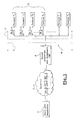
- Figure 1 schematically illustrates the principle of communication of multi-transmission data provided by the IGMP (Internet Group management) protocol Protocol) of the Internet Engineering Task Force (IETF) on a transmission medium “broadcast” wired, such as Ethernet network.
- IGMP Internet Group management protocol Protocol
- IETF Internet Engineering Task Force
- the main problem of the multi-transmission peripheral router 6 is to determine whether or not to forward the received packets. His concern is therefore to find out if there is at least one terminal participating in the group identified by the address of the multi-transmission packet it has just received from the Internet 2.
- the aforementioned IGMP protocol defined by the IETF, under the reference RFC 1112, has a group holding mechanism allowing a multi-transmission router local to find out if there are always member terminals (at least one) for a multi-transmission group given in subnetwork 8. This allows it to decide whether it should always route traffic from this group to the network or whether it should stop.
- This mechanism is simply that the router 6 sends periodically a query established by the IGMP, called “membership query” (from English “membership query”). This query is received by all T1-Tr terminals connected to the local network 8. A terminal that wishes to remain or become a member of a group G must respond to router 6 with a message called “membership report” (from the English “membership report”) to let him know that he is still interested in trafficking this group.
- the standard specifies that the router does not need the exhaustive list of all member terminals, but only to know if there is at least one, or none. Through therefore, it seems unnecessary that all members answer the question, disturb other participants for decoding their own response and also create a overload on the network.
- a single response is sufficient to inform router 6, the standard specifies that each terminal, upon receipt of the query, triggers a timer of a duration random before responding. During this time, each terminal listens to the line to watch for a response from any other terminal. If the timer of a terminal expires when no response has been seen on the line, then only this terminal sends its response. This response is seen by the other terminals which react by interrupting their timer without transmitting their response. This provision thus ensures that with each interrogation sent by the peripheral router 6, only one response is returned, regardless of the constitution of the terminal group, and the overload problem is avoided.
- RFC 1112 cannot be exploited when the subnet (such as a network of satellite terminals or the like) does not allow a terminal to watch for the responses sent to router 6 by another terminal.
- the organization of such a subnetwork and its multi-transmission operation will be described in the context of a network of satellite terminals, with reference to FIG. 2.
- the communication system is similar to that of Figure 1, except that the sub-network 80 is made up of satellite communication channels.
- the example is based on a type A satellite access network architecture 9780 NG.
- the multi-transmission data source 4 is connected to a router device 6 compliant with the IGMP protocol via the Internet 2, it being understood that this source can however be connected to the router by any other communication channel.
- Router 6 communicates with ST1-STr satellite terminals via a station terrestrial 10, known by the term "gateway", comprising an associated transceiver to a satellite antenna, the gateway and the router being connected by a transmission cable bidirectional 9 or the like.
- Gateway 10 establishes a communication link on a geostationary telecommunications satellite 12 which serves as a relay for all of the ST1-STr satellite terminals.
- Each ST satellite terminal includes a satellite dish with its high frequency transmit-receive circuits 14 connected to a personal computer PC or other communication equipment via a IGMP 15 host.
- the router 6 can therefore send multi-transmission data packets to terminals satellite and receive messages from them.
- Each satellite terminal can receive (or more exactly hear) all forward link messages, including those to other terminals, but only the gateway 10 can receive messages from a terminal. This is explained by the fact that the channels most often use a reception frequency f1 (common to all terminals) necessarily different from their transmission frequency f2 (common or not all terminals), which does not allow them to hear the broadcasts of others terminals. (It should be noted that the idea of adding the means to the satellite terminal to listen to this second frequency can only be achieved, at the cost of material elements relatively expensive including a second reception chain and a duplexer).
- the gateway 10 can receive the responses "report of ST satellite terminals, while all these terminals receive the "membership query” message sent only once by the gateway 10 and bearing either the multi-transmission address of all the terminals, or the multi-transmission address of the group for which it issues this "membership query” message.
- geostationary satellite transmission systems induce minimum delay of approximately 270 milliseconds (ms) between transmission by the source (router device 6) and reception by the recipient (terminal ST), which makes the solution IETF even more inapplicable.
- the standard mechanism used for cable subnets based on the monitoring between terminals and the interruption of the transmission of responses by the time-controlled terminals, unfortunately cannot operate on a link satellite or the like which links the terminals to a central IGMP router (or function), whether either behind a gateway or in a satellite network management center (NCC).
- NCC satellite network management center
- IGMP version 2 allows Router 6 to request ST terminals for a response within 25.6 seconds maximum. If a lower value is chosen, for example 5 seconds, traffic is concentrated on this lower duration of 5 seconds.
- Radio frequency transmission systems radio frequency One of the fundamental characteristics of transmission systems radio frequency is the limitation of the frequency band that can be used for each of these systems.
- the transmission capacity of the latter is fundamentally linked to the allocated frequency band. Optimizing the transmission capacity while minimizing the number, size or duration of messages is a constant concern of designers of radio frequency transmission systems.
- an object of the invention is to allow the systems of communication on a network whose transmission medium is not of the “en broadcasting ", which therefore do not allow listening between terminals, to benefit nevertheless provisions to reduce redundancy in response messages from others multi-transmission terminals.
- the invention provides a method for managing the communication of data packets in multi-transmission mode, the packets being transmitted from a transmission side of a transmission medium and received by terminals on a reception side. of this medium, in which method a query message is sent to the terminals in order to determine the presence of an active group of terminals according to the reception of at least one response message from a terminal of the of this group, characterized in that it comprises the step of transmitting from said transmission side and to said terminals a signal indicating the reception, at the transmission side, of at least one response message from a terminal of said group of terminals, so that terminals that have not sent a response message can act accordingly, in particular by interrupting their own response transmission process.
- the management is carried out in accordance with the IGMP protocol ("Internet Group Management Protocol"), said interrogation message being the message "membership query” and said response message being the message "report of 'membership'.
- the transmission of a response message by a group terminal can then be governed by the RFC ("Request for Comments") 1112 protocol of said IGMP protocol.
- the signal transmitted from the transmission side is the return to the terminals of at least one response message from the group.
- the transmission step can then consist of systematically returning to the terminals each response message received from the group, or to return to the terminals a number of response messages received less than the total of response received from a group terminal, to lighten data traffic.
- the number of response messages received returned may be a fraction (1 / N) of the total number of response messages received, where N is a number fixed or scalable.
- the signal is transmitted via a gateway on a radio frequency link which serves to broadcast said data packets (DP) in multi-transmission using, for the reception of said data packets (DP) transmitted in multiple transmission by the terminals of the transmission medium, for which this gateway is responsible for the mechanisms multi-transmission type "IGMP multicast", the transmission medium not allowing mutual listening between terminals.
- a gateway on a radio frequency link which serves to broadcast said data packets (DP) in multi-transmission using, for the reception of said data packets (DP) transmitted in multiple transmission by the terminals of the transmission medium, for which this gateway is responsible for the mechanisms multi-transmission type "IGMP multicast", the transmission medium not allowing mutual listening between terminals.
- the aforementioned step of emission can be carried out by a management unit between, or to, the gateway and a router which transmits the data packets in multi-transmission mode to the terminals.
- the management unit can then transmit to the router at least one of the response received from the terminal group. We can then implement the method of the invention with an existing router.
- the transmission step can also be carried out by means functionally integrated into a router which transmits multi-transmission data packets to the terminals.
- the invention provides a management device intended to intervene in a data packet communication system in multi-transmission mode according to which the packets are transmitted from a transmission side of a transmission medium and received by terminals on a reception side of this support, mutually isolated, in which management a query message is sent to the terminals in order to determine the presence of an active group of terminals according to the reception of at least one message from response from a terminal in this group, characterized in that it comprises return means for transmitting from said transmission side and to said terminals a signal indicating the reception, at the reception side, of at least one response message from a terminal of said group of terminals, so that the terminals that have not sent a response message can act accordingly, in particular by interrupting their own response transmission process.
- the invention provides a router, characterized in that it integrates the aforementioned device.
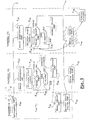
- the flowchart in Figure 3 indicates the main steps performed at the level of the gateway 10 and of two satellite terminals TSi and TSj among a group of terminals active, i.e. participating in a multi-transmission session of data packets issued from this gateway.
- the data transmission system is similar to that in Figure 2 and will not be described again for the sake of brevity.
- TSi terminals and TSj therefore receive the multi-transmission data packets routed by the router IGMP 6 satellite, and have the possibility of transmitting messages to it, by link satellite via gateway 10.
- the terminals are typically PC personal computers, each connected via a respective IGMP host 15 to a satellite transceiver with a satellite dish 14.
- the assembly consisting of the host 15 and the computer integrates material means and software to manage the reception of multi-transmission data packets in accordance with the IGMP protocol and the RFC 1112 standard described above.
- each satellite terminal has a timer enabling a random time interval (of a value between 0 seconds and the time of maximum response defined by the IGMP 6 satellite router in the "interrogation" message of membership ") between the receipt of a" membership query “message ("membership query”), hereinafter referred to as "IGMP query”, and the broadcast conditional of a response of "membership report”, hereinafter referred to as "IGMP response”.
- the process begins with transmission from gateway 10 (i.e. the side transmission E) of an IGMP interrogation intended for the group comprising the terminals TSi and TSj, established in accordance with RFC 1112 (step E20). This question is received with a delay of approximately 270 milliseconds (ms) by each of the terminals of the group (step E22).
- each terminal On receipt of this interrogation, each terminal sets its timer to establish the aforementioned random time interval (step E24).
- intervals i.e. timers
- TSi and TSj respectively values ti and tj, with the interval ti being the shortest of all the terminals in the group, hence the condition tj> ti.
- step E26 the terminals watch for the presence of a possible IGMP response coming from another terminal (step E26) by checking that their time interval has not expired (step E28), like the RFC 1112 process applied to a network wired as described in the context of FIG. 1.
- step E28 the protocol layers of the satellite terminals to handle IGMP query and response messages are the same as those of a terminal operating on a wired network.
- step E26 of watching for answers is not done by listening to others terminals on the same transmission channel (frequency f2) - this being impossible - but by listening to the reception channel, namely the link channel go to the frequency carrier f1, as will appear below.
- the terminal TSi emits its IGMP response (i.e. from the reception side R of the multicast data), always in accordance with the RFC 1112 standard (step E30). This transmission is performed on the return link to the carrier frequency f2, so that only the gateway 10 can detect it.
- step E32 upon receipt of the IGMP response by the gateway 10 (step E32), said response is automatically returned (from the sending side E) as is in multiple transmission on the link go to all the group's terminals by (step E34).
- This IGMP response return is managed by a unit on the side of gateway 10 of the satellite link, as will be described with reference to FIGS. 6 and 7.
- this terminal will be able to react to the reception of the return of the IGMP response by interrupting its timeout process (step E38), without transmitting its own IGMP response. More precisely, the terminal Tj will destroy its message of IGMP response with the interruption of the timer.
- each terminal in the group has the possibility of having at a given moment the shortest random time interval ti. Also, each terminal is capable of carrying out the steps of transmitting an IGMP response (E30) and interruption of the process (E38) if necessary (cf. dotted boxes).
- the invention makes it possible to greatly reduce the number of IGMP responses issued on the return link compared to a conventional approach whereby all participating terminals of the group would systematically send their IGMP response to expiration of their time delay.
- the corresponding gain in terms of band release bandwidth on the return link can be evaluated according to the following calculation.
- the value of the random time interval started in step E24 above for all of the group's terminals is evenly distributed between 0 and a limit value transmitted by router 6 to the terminals in the message which includes the IGMP query.
- This value is at most equal to 25.6 seconds; if we use this maximum value, and taking as delay between the emission of the response IGMP by the first terminal expiring (step E30) and receiving the return of this response (step E36) a round trip time on the satellite link, ie approximately 2 x 0.27s, the percentage of terminals in the group having issued their own IGMP response will be 100 x 2 x 0.27 / 25.6, or about 2.1%.
- step E34 the issue of IGMP response returns (step E34) implied by the process in accordance with the invention results in very little traffic overload, of the same order as traffic IGMP responses on the return link (2%). Even by accumulating responses IGMP on the outward and return routes, the balance remains very favorable: 2 x 2% against 100%).
- the process according to the invention has the advantage of having no impact on the IGMP protocol stack present in the PC user terminal and / or the host 15, nor on the IGMP 6 router protocol stack present on the side of gateway 10. It can thus be implemented seamlessly with router and router equipment terminals designed to apply the RFC 1112 standard for cable networks or like.
- each response received at the level of the gateway 10 is systematically returned to the terminals (step E34).
- IGMP response returns are filtered on the side of the gateway 10 so that only one response out of N responses received in step E32 is returned to step E34, where N is a constant or dynamically changing number.
- step E40 Upon receipt of each IGMP response (detected in step E32), in starting with the first (from TSi terminal), a counter is incremented by one (step E40) from an initial value of zero, and it is checked whether the value totaled by the counter has reached the aforementioned value N (step E42). In the example, this value N is memorized (step E44) so that it can be changed if necessary. As long as the number of responses received remains less than N, the process remains pending receipt of the following answer.
- step E34 for sending the IGMP response return.
- the counter is then reset to zero (step E46), the accounting cycle for responses received is continued (steps E40 and following). In this way, only a 1 / N fraction of the IGMP responses received are subject to a back to the group's terminals.
- the method can revise the value of N (step E48) according to different criteria to take into account for example the evolution of the group of terminals participants, traffic, reliability required, etc. This revision can be based in particular on the total number of returns made in step E34 following the issuance of the corresponding IGMP interrogation (step E20, FIG. 3).
- the value N can be adjusted, for example, so that this absolute number of returns remains substantially constant despite variations in the number of terminals participating in receiving packets of multi-transmission data.
- the 2000 x 5000 10 million potential IGMP responses will be reduced to 50,000 real IGMP responses on the return link, and will only induce around 5,000 returns from IGMP response retransmitted by the gateway on the forward path.
- Bandwidth initially required of 75 Mbits / s can thus be reduced to 250 Kbits / s on the return channel, and the method only induces a charge of 25 Kbits / s on the outgoing channel.
- Figure 5 is a flowchart of another variant, which differs from that of FIG. 4 by the fact that the first IGMP response received from the side of the gateway 10 after the emission of an IGMP interrogation having caused it is systematically returned to the start of accounting.
- This arrangement makes it possible to react more quickly by avoiding a first count to N before performing a return response, by means of a additional step of detecting IGMP queries issued in the process.
- step E50 it is determined (step E50), after reception an IGMP response in step E32, if this is the first response since the emission of the interrogation that provoked it. If so, this response is immediately returned to the group terminals (step E34 ') and the process then continues from the same way as for the variant of figure 4, by emitting only one response on N.
- the steps E34-E48 are identical to those of FIG. 4 and will not be repeated by conciseness.
- the IGMP response return mechanism according to the invention can be set implemented either by a specific IGMP response response management unit located between router 6 and gateway 10, either by integration into the protocol stack IGMP of the router.
- the unit 52 comprises a microprocessor and communication interfaces to accomplish the tasks of detection and return of IGPM responses according to the process according to the flowcharts of FIGS. 3, 4 or 5.
- the unit 52 can thus also include means of statistical analysis of returns to establish the value of N above according to determined criteria, and manage the returns of an IGMP response on N received.
- the IGMP response management unit 52 can, for example, transmit IGMP responses selectively to the router and systematically to terminals, or vice versa.
- the routing of IGMP responses by the unit 52 can be done in a way very simple on the one hand by identifying this answer, by reference to the corresponding field in the response message, and further by routing the response, if any, to the TS terminals (to perform the return step E34) and / or to the router 6.
- the unit 52 also proceeds to the identification of the IGMP query sent by the router 6 to establish the point of departure for the identification of the first IGMP response received (cf. step E50), simply by reference to the corresponding field of this message.
- IGMP 52 response management unit separately of router 6 allows the invention to be implemented with pre-existing routers, such as those designed for a cable network using the RFC 1112 standard.
- Figure 7 illustrates the case of the IGMP response return mechanism when it is integrated into the router's IGMP protocol stack. The features described are then implemented in a section 6 'of the router 6, at the head of the link 9 to the gateway 10. This section 6 ′ is managed just like the unit 52 in FIG. 6, but so centralized by the hardware and software means of the router 6.
- this other message can be established specifically by convention between the TS terminals and the router 6 and / or the gateway 10 so that its reception by the terminals interrupts the transmission of the IGMP response.
- the invention is in no way limited to "interrogation" messages membership "(" membership query ") and" membership report “(" membership report "), according to the IGMP standard, nor to RFC 1112 and RFC 2236, its scope application covering all other protocols and standards, present and future, where lessons given can be applied in an equivalent or analogous manner.
Landscapes
- Engineering & Computer Science (AREA)
- Signal Processing (AREA)
- Physics & Mathematics (AREA)
- Astronomy & Astrophysics (AREA)
- General Physics & Mathematics (AREA)
- Computer Networks & Wireless Communication (AREA)
- Data Exchanges In Wide-Area Networks (AREA)
- Radio Relay Systems (AREA)
Abstract
Description
- diffusion de programmes télévisuels,
- diffusion de quotations boursières en temps réel,
- visioconférences,
- commerce en ligne (enchères),
- distribution de stocks,
- etc.
- la réception quasi simultanée, par chaque terminal membre d'un groupe de pluri-transmission, d'un même paquet de données de pluri-diffusion DPi retransmis par le routeur périphérique 6,
- la transmission de messages d'un terminal quelconque vers le routeur périphérique 6,
- l'écoute par un terminal quelconque des messages transmis vers le routeur par tout autre terminal, et
- l'échange de données entre les terminaux.
- le côté envoi des données de pluri-diffusion, soit généralement le côté du routeur 6 ou d'une passerelle d'accès au support. Ce côté est repéré par la lettre E ; et
- le côté réception des données de pluri-diffusion, soit généralement le côté à l'entrée des terminaux T1-Tn. Ce côté est repéré par la lettre R. Pour une séance donnée de pluri-transmission, le routeur 6 identifie le groupe G de terminaux participants, auxquels les paquets de données doivent être transmis. Le groupe G de terminaux participant est identifié par une adresse dans chaque paquet DP reçu par le routeur 6. Ce groupe G peut concerner un nombre variable et évolutif de terminaux, allant d'un seul à l'intégralité des terminaux servis par le routeur. Dans l'exemple de la figure 1, le groupe G est constitué de n terminaux T1-Tn, représentés en cours de réception du même paquet de données DPi. On note que plusieurs groupes de pluri-transmission différents peuvent être servis par un même routeur 6, certains terminaux pouvant par ailleurs participer à plusieurs groupes simultanément. De même, la source de pluri-transmission 4 peut transmettre les paquets de données à plusieurs routeurs périphériques différents.
- une liaison aller depuis une passerelle 10 vers les terminaux satellite ST en écoute de cette fréquence porteuse radio (désignée f1), et
- une liaison retour sur une autre fréquence porteuse radio (désignée f2), associée à la liaison aller, pour véhiculer les messages depuis les terminaux satellite ST vers la passerelle 10.
caractérisé en ce qu'il comprend l'étape d'émission depuis ledit côté émission et vers lesdits terminaux d'un signal indiquant la réception, au côté émission, d'au moins un message de réponse provenant d'un terminal du dudit groupe de terminaux, afin que les terminaux n'ayant pas émis de message de réponse puissent agir en conséquence, notamment en interrompant leur propre processus d'émission de réponse.
Avantageusement, la gestion est réalisée conformément au protocole IGMP ("Internet Group Management Protocol"), ledit message d'interrogation étant le message "interrogation d'appartenance" ("membership query") et ledit message de réponse étant le message "rapport d'appartenance" ("membership report").
caractérisé en ce qu'il comprend des moyens de retour pour émettre depuis ledit côté émission et vers lesdits terminaux un signal indiquant la réception, au côté réception, d'au moins un message de réponse provenant d'un terminal dudit groupe de terminaux, afin que les terminaux n'ayant pas émis de message de réponse puissent agir en conséquence, notamment en interrompant leur propre processus d'émission de réponse.
- la figure 1, déjà décrite, est un schéma simplifié d'un système connu de pluri-transmission de paquets de données sur réseau Internet et sur un réseau local câblé, tel que Ethernet, permettant aux terminaux communicants de s'écouter ;
- la figure 2, déjà décrite, est un schéma simplifié d'un système de transmission de paquets de données via un réseau de terminaux satellite servi par une passerelle, qui constitue un exemple de terminaux communicants ne pouvant pas s'écouter, et pour lequel l'invention peut être mise en oeuvre dans le cadre d'une diffusion en pluri-transmission ;
- la figure 3 est un organigramme servant à expliquer le principe de l'invention dans le cadre du système de la figure 2 ;
- la figure 4 est un organigramme d'une première variante appliquée au concept présenté à la figure 3 ;
- la figure 5 est un organigramme d'une deuxième variante appliquée au concept présenté à la figure 3 ;
- la figure 6 reprend une partie du schéma de la figure 2 pour montrer une première implantation fonctionnelle possible d'une unité de gestion de retours de réponses IGMP conforme à l'invention ; et
- la figure 7 reprend une partie du schéma de la figure 2 pour montrer une deuxième implantation fonctionnelle possible d'une unité de gestion de retours de réponses IGMP conforme à l'invention
- chaque réponse IGMP reçue des terminaux est systématiquement transmise vers le routeur 6. Ainsi, dans le cadre du mode de réalisation de la figure 3, l'unité 52 adresse chaque réponse IGMP reçue d'une part à tous les terminaux TS1-TSn du groupe concerné (étape E34) et d'autre part au routeur 6; ou
- une proportion seulement des réponses IGMP reçues des terminaux est transmise vers le routeur 6. Dans le cadre des variantes des figures 4 et 5, cette proportion peut être tout simplement égale à 1/N. L'unité 52 peut alors, à chaque retour de réponse IGMP adressée aux terminaux TS, adresser cette réponse en outre au routeur 6. On peut aussi prévoir que le nombre de réponses IGMP transmises au routeur 6 par l'unité 52 représente un proportion 1/M différente de 1/N, M étant un valeur fixe ou évolutive.
Claims (27)
- Procédé de gestion de la communication de paquets de données (DP) en mode de pluri-transmission, les paquets étant émis depuis un côté émission (E) d'un support de transmission (80) et reçus par des terminaux (TS1-TSr) à un côté réception (R) de ce support, le support physique de cette transmission ne permettant pas l'écoute mutuelle entre les terminaux, procédé dans lequel on émet (E20) un message d'interrogation vers les terminaux afin de déterminer la présence d'un groupe actif (G) de terminaux en fonction de la réception (E32) d'au moins un message de réponse provenant d'un terminal du de ce groupe,
caractérisé en ce qu'il comprend l'étape d'émission (E34), depuis ledit côté émission (E) et vers lesdits terminaux (TS1-TSr), d'un signal indiquant la réception, au côté émission, d'au moins un message de réponse provenant d'un terminal du dudit groupe (G) de terminaux, afin que les terminaux n'ayant pas émis de message de réponse puissent agir en conséquence, notamment en interrompant leur propre processus d'émission de réponse. - Procédé la revendication 1, caractérisé en ce que la gestion est réalisée conformément au protocole IGMP ("Internet Group Management Protocol"), ledit message d'interrogation étant le message "interrogation d'appartenance" ("membership query") et ledit message de réponse étant le message "rapport d'appartenance" ("membership report").
- Procédé selon la revendication 2, caractérisé en ce que l'émission d'un message de réponse par un terminal (TS1-TSr) du groupe (G) est régie par le protocole RFC ("Request for Comments") 1112 dudit protocole IGMP.
- Procédé selon l'une quelconque des revendications 1 à 3, caractérisé en ce que ledit signal émis depuis le côté émission (E) est le retour vers les terminaux (TS1-TSr) d'au moins un message de réponse provenant d'un terminal dudit groupe (G).
- Procédé selon la revendication 4, caractérisé en ce que l'étape d'émission (E34)consiste à retourner systématiquement vers les terminaux (ST1-STr) chaque message de réponse reçu provenant d'un terminal (TS1-TSr) du groupe (G).
- Procédé selon la revendication 4, caractérisé en ce que l'étape d'émission (E34) consiste à retourner vers les terminaux (ST1-STr) un nombre de messages de réponse reçus inférieur au total des messages de réponse reçus.
- Procédé selon la revendication 6, caractérisé en ce que le nombre de messages de réponse reçus retournés est une fraction (1/N) du nombre total des messages de réponse reçus, où N est un nombre fixe ou évolutif.
- Procédé selon la revendication 7, caractérisé en ce que l'on fait évoluer la valeur N de manière dynamique en fonction des conditions d'utilisation du réseau (80) afin de maintenir sensiblement constant le nombre de messages de réponse reçus retournés lors de l'étape d'émission (E34), pour chaque message d'interrogation émis.
- Procédé selon l'une quelconque des revendication 2 à 8, caractérisé en ce que ledit signal est émis via une passerelle (10) d'une liaison radiofréquence qui sert à diffuser lesdits paquets de données (DP) en pluri-transmission utilisant, pour la réception desdits paquets de données (DP) émis en pluri-transmission par les terminaux du support de transmission, pour lequel cette passerelle est responsable des mécanismes de pluri-transmission de type « pluri-diffusion IGMP », le support de transmission ne permettant pas l'écoute mutuelle entre terminaux .
- Procédé selon la revendication 9, caractérisé en ce que ledit support de transmission (80) est une liaison radiofréquence par satellite (12), lesdits terminaux (ST1-STr) étant des terminaux satellites, l'émission des paquets de données (DP) en pluri-transmission et l'émission (E34) dudit signal s'effectuant sur une liaison aller à une première fréquence porteuse (f1) et l'émission (E30) du ou des message(s) de réponse par le groupe (G) de terminaux satellite s'effectuant sur une liaison retour à une deuxième fréquence porteuse (f2) différente de la première.
- Procédé selon la revendication 9 ou 10, caractérisé en ce que l'étape d'émission (E34) est effectuée par une unité de gestion (52) entre, ou à, la passerelle (10) et un routeur (6) qui émet lesdits paquets de données (DP) en mode de pluri-transmission vers les terminaux (TS1-TSr).
- Procédé selon la revendication 11, caractérisé en ce que l'unité de gestion (52) fonctionne de manière transparente vis-à-vis du routeur (6), transmettant à ce dernier transmet au routeur (6) au moins un des messages de réponse reçus du groupe (G) de terminaux (TS1-TSr).
- Procédé selon la revendication 9 ou 10, caractérisé en ce que l'étape d'émission (E34) est réalisée par des moyens (6') fonctionnellement intégrés à un routeur (6) qui émet les paquets de données (DP) de pluri-transmission vers les terminaux (TS1-TSr).
- Dispositif de gestion destiné à intervenir dans un système de communication de paquets de données (DP) en mode de pluri-transmission selon lequel les paquets sont émis depuis un côté émission (E) d'un support de transmission (80) et reçus par des terminaux (TS1-TSr) à un côté réception (R) de ce support, le support physique de transmission ne permettant pas l'écoute mutuelle entre les terminaux, dans laquelle gestion on émet (E20) un message d'interrogation vers les terminaux afin de déterminer la présence d'un groupe actif (G) de terminaux en fonction de la réception (E32) d'au moins un message de réponse provenant d'un terminal de ce groupe,
caractérisé en ce qu'il comprend des moyens de retour (6'; 52) pour émettre (E34) depuis ledit côté émission (E) et vers lesdits terminaux (TS1-TSr) un signal indiquant la réception, au côté émission, d'au moins un message de réponse provenant d'un terminal dudit groupe (G) de terminaux, afin que les terminaux n'ayant pas émis de message de réponse puissent agir en conséquence, notamment en interrompant leur propre processus d'émission de réponse. - Dispositif selon la revendication 14, caractérisé en ce qu'il réalise la gestion conformément au protocole IGMP ("Internet Group Management Protocol"), ledit message d'interrogation étant le message "interrogation d'appartenance" ("membership query") et ledit message de réponse étant le message "rapport d'appartenance" ("membership report")
- Dispositif selon la revendication 15, caractérisé en ce que l'émission d'un message de réponse par un terminal (TS1-TSr) du groupe (G) est régie par le protocole RFC ("Request for Comments") 1112 dudit protocole IGMP.
- Dispositif selon l'une quelconque des revendications 14 à 16, caractérisé en ce que ledit signal émis depuis le côté émission (E) est le retour vers les terminaux (TS1 - TSr) d'au moins un message de réponse provenant d'un terminal dudit groupe (G).
- Dispositif selon la revendication 17, caractérisé en ce qu'il retourne systématiquement vers les terminaux (ST1-STr) chaque message de réponse reçu provenant d'un terminal (TS1-TSr) du groupe (G).
- Dispositif selon la revendication 17, caractérisé en ce qu'il retourne vers les terminaux (ST1-STr) un nombre de messages de réponse reçus inférieur au total des messages de réponse reçus.
- Dispositif selon la revendication 19, caractérisé en ce que le nombre de messages de réponse reçus qu'il retourne est une fraction (1/N) du nombre total des messages de réponse reçus, où N est un nombre fixe ou évolutif.
- Dispositif selon la revendication 20, caractérisé en ce qu'il comprend des moyens pour faire évoluer la valeur N de manière dynamique en fonction des conditions d'utilisation du réseau (80) afin de maintenir sensiblement constant le nombre de messages de réponse reçus retournés pour chaque message d'interrogation émis.
- Dispositif selon l'une quelconque des revendication 14 à 21, caractérisé en ce qu'il émet ledit signal via une passerelle (10) d'une liaison radiofréquence qui sert à diffuser lesdits paquets de données (DP) en pluri-transmission utilisant, pour la réception desdits paquets de données (DP) émis en pluri-transmission par les terminaux du support de transmission, pour lequel cette passerelle est responsable des mécanismes de pluri-transmission de type « pluri-diffusion IGMP », le support de transmission ne permettant pas l'écoute mutuelle entre terminaux
- Dispositif selon la revendication 22, caractérisé en ce que ledit support de transmission est une liaison radiofréquence par satellite (12), lesdits terminaux (ST1-STr) étant des terminaux satellites, l'émission des paquets de données (DP) en pluri-transmission et l'émission (E34) dudit signal s'effectuant sur une liaison aller à une première fréquence porteuse (f1), et l'émission (E30) du ou des message(s) de réponse par le groupe (G) de terminaux satellite s'effectuant sur une liaison retour à une deuxième fréquence porteuse (f2) différente de la première.
- Dispositif selon la revendication 22 ou 23, caractérisé en ce qu'il est implanté entre, ou à, la passerelle (10) et un routeur (6) qui émet lesdits paquets de données (DP) en mode de pluri-transmission vers les terminaux (TS1-TSr).
- Dispositif selon la revendication 24, caractérisé en ce qu'il fonctionne de manière transparente vis-à-vis du routeur (6), transmettant à ce dernier transmet au routeur (6) au moins un des messages de réponse reçus du groupe (G) de terminaux (TS1-TSr).
- Dispositif selon la revendication 22 ou 23, caractérisé en ce qu'il est fonctionnellement intégré à un routeur (6) qui émet les données de pluri-transmission vers les terminaux (TS1-TSr).
- Routeur (6, 6'), caractérisé en ce qu'il intègre un dispositif selon l'une quelconque des revendications 14 à 26.
Applications Claiming Priority (2)
| Application Number | Priority Date | Filing Date | Title |
|---|---|---|---|
| FR0107956 | 2001-06-18 | ||
| FR0107956A FR2826211B1 (fr) | 2001-06-18 | 2001-06-18 | Procede et dispositif d'allegement de la charge de signalisation d'un protocole "pluri-transmission" utilisant un support de transmission ne permettant pas l'ecoute mutuelle entre terminaux d'un reseau |
Publications (1)
| Publication Number | Publication Date |
|---|---|
| EP1271817A1 true EP1271817A1 (fr) | 2003-01-02 |
Family
ID=8864434
Family Applications (1)
| Application Number | Title | Priority Date | Filing Date |
|---|---|---|---|
| EP02291350A Withdrawn EP1271817A1 (fr) | 2001-06-18 | 2002-06-03 | Procédé et dispositif d'allégement de la charge de signalisation dans un réseau, qui utilise un protocole "pluri-transmission" |
Country Status (3)
| Country | Link |
|---|---|
| US (1) | US7248598B2 (fr) |
| EP (1) | EP1271817A1 (fr) |
| FR (1) | FR2826211B1 (fr) |
Cited By (1)
| Publication number | Priority date | Publication date | Assignee | Title |
|---|---|---|---|---|
| CN101719928B (zh) * | 2009-11-24 | 2012-05-23 | 福建星网锐捷网络有限公司 | 一种队列调度调节方法、装置及交换机 |
Families Citing this family (13)
| Publication number | Priority date | Publication date | Assignee | Title |
|---|---|---|---|---|
| US7359939B2 (en) * | 2002-12-06 | 2008-04-15 | Alcatel Canada, Inc. | Fast service restoration for lost IGMP leave requests |
| US7817534B2 (en) | 2003-11-10 | 2010-10-19 | Motorola, Inc. | Method and apparatus for interrupting a transmission of a multicast signal |
| FI117033B (fi) * | 2004-02-24 | 2006-05-15 | Valtion Teknillinen | Hajautettu dynaaminen reititys |
| JP2006101471A (ja) * | 2004-09-06 | 2006-04-13 | Hitachi Communication Technologies Ltd | マルチキャスト冗長経路ルータ、マルチキャスト冗長化方式 |
| US7362776B2 (en) * | 2004-11-01 | 2008-04-22 | Cisco Technology, Inc. | Method for multicast load balancing in wireless LANs |
| US7489684B2 (en) * | 2004-12-08 | 2009-02-10 | Alcatel Lucent | Access network architecture for multicasting using xDSL and IGMP |
| US7733868B2 (en) | 2005-01-26 | 2010-06-08 | Internet Broadcasting Corp. | Layered multicast and fair bandwidth allocation and packet prioritization |
| JP4840306B2 (ja) * | 2007-09-18 | 2011-12-21 | 富士通株式会社 | 通信抑制方法、通信抑制装置、および通信抑制プログラム |
| US8489134B2 (en) | 2008-09-02 | 2013-07-16 | Cisco Technology, Inc. | System and method for providing presence based trunking in a network environment |
| CN102377576B (zh) * | 2010-08-06 | 2014-09-17 | 高通创锐讯通讯科技(上海)有限公司 | 多播的实现方法 |
| CN102439889B (zh) * | 2011-10-14 | 2014-04-02 | 华为技术有限公司 | 提升组播接收增益的方法及系统 |
| US8638789B1 (en) * | 2012-05-04 | 2014-01-28 | Google Inc. | Optimal multicast forwarding in OpenFlow based networks |
| CN111555983B (zh) * | 2020-03-26 | 2023-03-24 | 航天恒星科技有限公司 | 一种面向天地的组播数据传输方法及装置 |
Citations (2)
| Publication number | Priority date | Publication date | Assignee | Title |
|---|---|---|---|---|
| WO1999016201A2 (fr) * | 1997-09-22 | 1999-04-01 | Zak Sat General Trading Co. Wll | Service internet utilisant des satellites asymetriques |
| EP0951198A2 (fr) * | 1998-04-14 | 1999-10-20 | Nec Corporation | Transmission à destinations multiples des paquets IP sur un réseau ATM sans fils |
Family Cites Families (6)
| Publication number | Priority date | Publication date | Assignee | Title |
|---|---|---|---|---|
| US6331983B1 (en) * | 1997-05-06 | 2001-12-18 | Enterasys Networks, Inc. | Multicast switching |
| WO2001076266A1 (fr) * | 2000-03-31 | 2001-10-11 | British Telecommunications Public Limited Company | Procede de determination de chemins de reseau |
| US20020150094A1 (en) * | 2000-10-27 | 2002-10-17 | Matthew Cheng | Hierarchical level-based internet protocol multicasting |
| US6947434B2 (en) * | 2000-11-16 | 2005-09-20 | Telefonaktiebolaget Lm Ericsson (Publ) | Subgroup multicasting in a communications network |
| US6885665B2 (en) * | 2000-11-30 | 2005-04-26 | At&T Corp. | Method for distributing calls to a group of end points |
| US6781999B2 (en) * | 2001-07-23 | 2004-08-24 | Airvana, Inc. | Broadcasting and multicasting in wireless communication |
-
2001
- 2001-06-18 FR FR0107956A patent/FR2826211B1/fr not_active Expired - Fee Related
-
2002
- 2002-06-03 EP EP02291350A patent/EP1271817A1/fr not_active Withdrawn
- 2002-06-17 US US10/171,623 patent/US7248598B2/en not_active Expired - Lifetime
Patent Citations (2)
| Publication number | Priority date | Publication date | Assignee | Title |
|---|---|---|---|---|
| WO1999016201A2 (fr) * | 1997-09-22 | 1999-04-01 | Zak Sat General Trading Co. Wll | Service internet utilisant des satellites asymetriques |
| EP0951198A2 (fr) * | 1998-04-14 | 1999-10-20 | Nec Corporation | Transmission à destinations multiples des paquets IP sur un réseau ATM sans fils |
Non-Patent Citations (2)
| Title |
|---|
| JOHNSON V ET AL: "IP MULTICAST: MAKING IT HAPPEN", DATA COMMUNICATIONS, MCGRAW HILL. NEW YORK, US, vol. 26, no. 7, 21 May 1997 (1997-05-21), pages 76 - 79,81, XP000695159, ISSN: 0363-6399 * |
| XYLOMENOS G ET AL: "IP multicasting for wireless mobile hosts", MILITARY COMMUNICATIONS CONFERENCE, 1996. MILCOM '96, CONFERENCE PROCEEDINGS, IEEE MCLEAN, VA, USA 21-24 OCT. 1996, NEW YORK, NY, USA,IEEE, US, 21 October 1996 (1996-10-21), pages 933 - 937, XP010204037, ISBN: 0-7803-3682-8 * |
Cited By (1)
| Publication number | Priority date | Publication date | Assignee | Title |
|---|---|---|---|---|
| CN101719928B (zh) * | 2009-11-24 | 2012-05-23 | 福建星网锐捷网络有限公司 | 一种队列调度调节方法、装置及交换机 |
Also Published As
| Publication number | Publication date |
|---|---|
| US7248598B2 (en) | 2007-07-24 |
| FR2826211B1 (fr) | 2004-12-10 |
| US20020191631A1 (en) | 2002-12-19 |
| FR2826211A1 (fr) | 2002-12-20 |
Similar Documents
| Publication | Publication Date | Title |
|---|---|---|
| US8948149B2 (en) | Access node/gateway to access node/gateway layer-2 connectivity (end-to-end) | |
| EP1271817A1 (fr) | Procédé et dispositif d'allégement de la charge de signalisation dans un réseau, qui utilise un protocole "pluri-transmission" | |
| WO2015049431A1 (fr) | Procede d'abonnement a des flux en provenance de clients multicast | |
| EP3787344A1 (fr) | Procédé de configuration d'un système d'extension de couverture de communication sans-fil et un système d'extension de couverture de communication sans-fil mettant en oeuvre ledit procédé | |
| EP2210396B1 (fr) | Système d'interconnexion entre au moins un appareil de communication et au moins un système d'information distant et procédé d'interconnexion | |
| WO1997048051A1 (fr) | Systeme de distribution de donnees a multidestination ip garantissant la qualite du service | |
| EP2156597A1 (fr) | Procede de reception de paquets de donnees et procede de transmission correspondant | |
| WO2011012569A1 (fr) | Procede et systeme pour la selection automatique de media de transmission | |
| EP3430777B1 (fr) | Procédé et système de gestion dynamique de chemins de communication entre routeurs en fonction de besoins applicatifs | |
| EP3050272B1 (fr) | Dispositif et procédé de gestion d'abonnement à des transmissions point-à-multipoint | |
| FR2991531A1 (fr) | Trames de controle de courte duree en couche physique | |
| EP3231190B1 (fr) | Procédé et dispositifs permettant une transmission d'un flux de données selon un mode de transmission multipoint | |
| FR3075530A1 (fr) | Procede d optimisation de l efficacite spectrale dans un contexte d interconnexion mpls | |
| FR2817419A1 (fr) | Procede et systeme de telecommunication multimedia par satellites | |
| WO2008096086A2 (fr) | Procede de traitement de perte de paquets | |
| FR3141586A1 (fr) | Procede et dispositif de gestion de messages diffuses dans un reseau local | |
| WO2002037762A1 (fr) | Procede et systeme pour la diffusion de messages multidestinations utilisant des representants | |
| EP2449727A1 (fr) | Dispositif de commande de l'ouverture de sessions, plateforme de service avec un tel dispositif, procédé, programme d'ordinateur et support d'information associés | |
| FR2868644A1 (fr) | Methode de decouverte d'appareils connectes a un reseau ip et appareil implementant la methode | |
| EP1036456B1 (fr) | Methode de communication client-serveur avec reseaux paralleles | |
| EP4459956A1 (fr) | Priorisation des flux de données entre une source de contenus audio-vidéos et des clients de télécommunication | |
| EP4408036A1 (fr) | Procédé de communication de messages entre une pluralité d'équipements d'utilisateur | |
| FR2925805A1 (fr) | Procede pour gerer la transmission de donnees en mode multidiffusion vers une pluralite d'elements de reseau, et element de reseau pour la mise en oeuvre du procede | |
| FR3096850A1 (fr) | Procede de transmission de donnees entre un emetteur et un recepteur dans un reseau de radiocommunications a capacite de bouclage local | |
| EP1037433A1 (fr) | Procédé de distribution de tables de routage dans un réseau de télécommunication |
Legal Events
| Date | Code | Title | Description |
|---|---|---|---|
| PUAI | Public reference made under article 153(3) epc to a published international application that has entered the european phase |
Free format text: ORIGINAL CODE: 0009012 |
|
| AK | Designated contracting states |
Kind code of ref document: A1 Designated state(s): AT BE CH CY DE DK ES FI FR GB GR IE IT LI LU MC NL PT SE TR |
|
| AX | Request for extension of the european patent |
Free format text: AL;LT;LV;MK;RO;SI |
|
| 17P | Request for examination filed |
Effective date: 20030702 |
|
| AKX | Designation fees paid |
Designated state(s): AT BE CH CY DE DK ES FI FR GB GR IE IT LI LU MC NL PT SE TR |
|
| 17Q | First examination report despatched |
Effective date: 20031010 |
|
| RAP1 | Party data changed (applicant data changed or rights of an application transferred) |
Owner name: ALCATEL LUCENT |
|
| RAP1 | Party data changed (applicant data changed or rights of an application transferred) |
Owner name: ALCATEL LUCENT |
|
| 111Z | Information provided on other rights and legal means of execution |
Free format text: AT BE CH CY DE DK ES FI FR GB GR IE IT LI LU MC NL PT SE TR Effective date: 20130410 |
|
| RAP1 | Party data changed (applicant data changed or rights of an application transferred) |
Owner name: ALCATEL LUCENT |
|
| D11X | Information provided on other rights and legal means of execution (deleted) | ||
| STAA | Information on the status of an ep patent application or granted ep patent |
Free format text: STATUS: THE APPLICATION IS DEEMED TO BE WITHDRAWN |
|
| 18D | Application deemed to be withdrawn |
Effective date: 20160518 |