EP1271762A2 - Stall detection and thermal protection for a vehicle with an electric motor - Google Patents
Stall detection and thermal protection for a vehicle with an electric motor Download PDFInfo
- Publication number
- EP1271762A2 EP1271762A2 EP02077179A EP02077179A EP1271762A2 EP 1271762 A2 EP1271762 A2 EP 1271762A2 EP 02077179 A EP02077179 A EP 02077179A EP 02077179 A EP02077179 A EP 02077179A EP 1271762 A2 EP1271762 A2 EP 1271762A2
- Authority
- EP
- European Patent Office
- Prior art keywords
- function
- signal indicative
- controller
- signal
- speed
- Prior art date
- Legal status (The legal status is an assumption and is not a legal conclusion. Google has not performed a legal analysis and makes no representation as to the accuracy of the status listed.)
- Granted
Links
- 238000001514 detection method Methods 0.000 title 1
- 238000004364 calculation method Methods 0.000 claims abstract description 15
- 230000020169 heat generation Effects 0.000 claims abstract description 15
- 238000004891 communication Methods 0.000 claims abstract description 11
- 238000000034 method Methods 0.000 claims abstract description 11
- 230000004044 response Effects 0.000 claims abstract description 8
- 238000001914 filtration Methods 0.000 claims abstract description 5
- 238000012545 processing Methods 0.000 claims abstract description 5
- 238000012886 linear function Methods 0.000 claims description 3
- 238000010586 diagram Methods 0.000 description 6
- 230000008901 benefit Effects 0.000 description 5
- 230000007704 transition Effects 0.000 description 5
- 238000013461 design Methods 0.000 description 4
- 238000005259 measurement Methods 0.000 description 4
- 238000013459 approach Methods 0.000 description 3
- 230000008859 change Effects 0.000 description 2
- 238000009499 grossing Methods 0.000 description 2
- 230000007246 mechanism Effects 0.000 description 2
- 230000002860 competitive effect Effects 0.000 description 1
- 230000003247 decreasing effect Effects 0.000 description 1
- 230000001419 dependent effect Effects 0.000 description 1
- 238000010438 heat treatment Methods 0.000 description 1
- 238000012986 modification Methods 0.000 description 1
- 230000004048 modification Effects 0.000 description 1
- 230000008569 process Effects 0.000 description 1
- 230000004043 responsiveness Effects 0.000 description 1
- 238000006467 substitution reaction Methods 0.000 description 1
Images


Classifications
-
- B—PERFORMING OPERATIONS; TRANSPORTING
- B62—LAND VEHICLES FOR TRAVELLING OTHERWISE THAN ON RAILS
- B62D—MOTOR VEHICLES; TRAILERS
- B62D5/00—Power-assisted or power-driven steering
- B62D5/04—Power-assisted or power-driven steering electrical, e.g. using an electric servo-motor connected to, or forming part of, the steering gear
- B62D5/0457—Power-assisted or power-driven steering electrical, e.g. using an electric servo-motor connected to, or forming part of, the steering gear characterised by control features of the drive means as such
- B62D5/046—Controlling the motor
- B62D5/0469—End-of-stroke control
-
- B—PERFORMING OPERATIONS; TRANSPORTING
- B62—LAND VEHICLES FOR TRAVELLING OTHERWISE THAN ON RAILS
- B62D—MOTOR VEHICLES; TRAILERS
- B62D5/00—Power-assisted or power-driven steering
- B62D5/04—Power-assisted or power-driven steering electrical, e.g. using an electric servo-motor connected to, or forming part of, the steering gear
- B62D5/0457—Power-assisted or power-driven steering electrical, e.g. using an electric servo-motor connected to, or forming part of, the steering gear characterised by control features of the drive means as such
- B62D5/0481—Power-assisted or power-driven steering electrical, e.g. using an electric servo-motor connected to, or forming part of, the steering gear characterised by control features of the drive means as such monitoring the steering system, e.g. failures
- B62D5/0487—Power-assisted or power-driven steering electrical, e.g. using an electric servo-motor connected to, or forming part of, the steering gear characterised by control features of the drive means as such monitoring the steering system, e.g. failures detecting motor faults
-
- H—ELECTRICITY
- H02—GENERATION; CONVERSION OR DISTRIBUTION OF ELECTRIC POWER
- H02P—CONTROL OR REGULATION OF ELECTRIC MOTORS, ELECTRIC GENERATORS OR DYNAMO-ELECTRIC CONVERTERS; CONTROLLING TRANSFORMERS, REACTORS OR CHOKE COILS
- H02P29/00—Arrangements for regulating or controlling electric motors, appropriate for both AC and DC motors
- H02P29/02—Providing protection against overload without automatic interruption of supply
Definitions
- the steering assist torque is provided by an electric motor that is typically coupled to a steering column or shaft.
- Electric motors and their control circuits and devices generate heat at a rate that increases with operating current, and are thus designed to operate within design limits chosen to prevent damage due to thermal overload.
- Electric motors used in vehicular systems are subject to a wide range of loads for highly varying periods of time.
- the electric motor in a vehicular electric power steering system may require only 15 Amperes ("A") of electrical current for long periods of time such as for continuous operation, but may require 75 A of current for shorter periods such as up to about 5 seconds.
- thermal sensors such as thermistors to directly measure temperature in a current limiting system.
- thermal sensors such as thermistors to directly measure temperature in a current limiting system.
- drawbacks including generally slow response, calibration overhead and difficult placement.
- a vehicular system includes a controller and an electric motor in signal communication with the controller for receiving current and rotating at speed; while the controller includes a first function responsive to a signal indicative of the speed of the electric motor, a filter responsive to a signal indicative of the heat generation rate of the vehicular system, a second function in signal communication with the first function and the filter, and a limit calculation function in signal communication with the second function for providing a motor current limit responsive to the second function; wherein a method for controlling the vehicular system includes receiving a signal indicative of the heat generation rate of the vehicular system, receiving a signal indicative of a speed of the electric motor, providing a scale factor or an overload value in response to the received signal indicative of speed, filtering the received signal indicative ofheat generation rate in correspondence with a time constant, processing the filtered signal by executing a multiplication by the scale factor or a comparison with the overload value to produce a signal indicative of compliance with a duty cycle requirement, and
- reference numeral 70 generally designates an electric power steering (“EPS") system for a motor vehicle.
- a steering mechanism 72 is a rack-and-pinion type mechanism that includes a toothed rack (not shown) and a pinion gear (also not shown) located under a gear housing 74.
- a steering wheel 76 is coupled to an upper steering shaft 78. As the steering wheel 76 is turned, the upper steering shaft 78, which is connected to a lower steering shaft 80 through a universal joint 82, turns the pinion gear. Rotation of the pinion gear moves the toothed rack, which moves tie-rods 84 (only one shown) that, in turn, move steering knuckles 86 (only one shown), which turn wheels 88 (only one shown).
- EPS assist torque is provided through an assist unit generally designated by reference numeral 90, which includes a controller 92 and an electric motor 94.
- a motor position commutation sensor 95 measures the position of the motor 94.
- the controller 92 is powered by a vehicular power supply 96 through a supply line 98.
- the controller 92 receives a signal indicative of the vehicle velocity on signal line 100.
- Initial hand-wheel position is measured by position sensor 102 and fed to the controller 92 through line 104.
- Position sensor 102 may be an optical-encoding type of sensor, a variable resistance type of sensor, or any other suitable type of position sensor for performing the functions of position sensor 102.
- the torque sensor 103 senses the torque applied to the steering wheel 76 by a vehicle operator.
- the torque sensor 103 may include a torsion bar (not shown) and a variable-resistance type of sensor (also not shown) that outputs a signal to controller 92 through line 106 in relation to the amount of twist on the torsion bar.
- Other suitable torque-sensing devices used with known signal processing techniques will suffice in alternate embodiments.
- the controller 92 In response to the inputs on lines 100, 104 and 106, the controller 92 sends a command signal through line 108 to the electric motor 94.
- the motor 94 supplies torque-assist to the steering system through a worm 107 and a worm gear 109, in order to provide a steering torque assist to the vehicular steering system in addition to a steering force exerted by the vehicle operator.
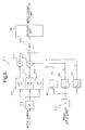
- a motor current limiter is indicated generally by the reference numeral 10.
- a portion of the controller 92 of FIG. 1 includes the motor current limiter 10.
- An input signal indicative of the measured or estimated electrical current consumption of the motor 94 of FIG. 1 is received and squared by a squarer 12.
- the resulting signal is then directed to a plurality of first-order low-pass filters ("LPF") 14, each of which has a different time constant ⁇ i .
- LPF first-order low-pass filters
- thermal systems are generally first order and are thus preferably treated to first-order filters
- higher order filters may be substituted in alternate embodiments where they may exhibit performance advantages for applications having unmodeled characteristics.
- An input signal indicative of motor speed (i.e., the absolute value of the motor angular velocity) is received by a comparator 18 and compared to a stall speed. If the motor speed is greater than the stall speed, an array of overload values corresponding to the plurality of LPFs 14 is set equal at assigner 20 to an array of maximum values allowable for a motor that is rotating. If on the other hand the motor speed is less than or equal to the stall speed, the array of overload values corresponding to the plurality of LPFs 14 is set equal at assigner 22 to an array of maximum values allowable for a motor that is substantially stalled.
- the comparator 18 and the assigners 20 and 22 together embody a binary-valued stall-detect vector function.
- the array of overload values is received, in turn, by the plurality of comparators 16 in a one-to-one correspondence with the plurality of associated LPFs 14.
- the array of comparators 16 determine whether any one of the squared and filtered signals received from LPFs 14 exceeds its corresponding overload value.
- a logical OR 24 enables a limit calculation function 26 if one or more of the array of overload values is exceeded.
- the limit calculation function 26, in turn, calculates a motor current limit corresponding to the squared and filtered signal that exceeded its overload value by an amount greater than that of each of the other squared and filtered signals. The motor current limit may then be used to limit the current supplied to the motor.
- an implementation of the motor current limiter 10 uses a signal indicative of motor current, which is squared and processed through the plurality of first-order low-pass filters.
- the filter rates differ by a factor of ten from filter to filter, with the longest time constant approaching 2000 seconds.
- the outputs of the filters are then compared to the square of the active duty-cycle requirement. Comparison to the square of the actual requirement obviates the need to take the square root of the filter outputs, and improves throughput.
- the active duty cycle requirement ("I maxi ") is either the stall requirement ("I max_stall ") or the non-stall requirement ("I max_rotate ").
- the decision on which requirement is set active depends upon the estimate or measurement of motor speed.
- the absolute value of this motor speed representation is compared to a calibratable value ("W stall ").
- the calibratable value represents a motor speed value which may be considered the "stall" condition, which is typically slightly greater than zero. Thus, any minor offsets in the measurement do not prevent the stall condition from being detected.
- a limit function is applied to the motor output command to reduce the motor current. When all of the filter outputs fall below the active requirement, the limit function is removed.
- the limit function is applied in a smooth and gradual manner to prevent abrupt hand-wheel effort changes.
- the amount of limiting is a linear function of the amount by which a filter output exceeds its active requirement.
- an alternate embodiment motor current limiter is indicated generally by the reference numeral 110.
- An input signal indicative of actual or estimated motor current is received and squared by a squarer 112.
- the resulting signal is then fed to a plurality of first-order low-pass filters ("LPF") 114, each of which has a different time constant ⁇ i .
- LPF first-order low-pass filters
- the squared and filtered signals are received, in turn, by a plurality of scaling functions 115.
- An input signal indicative of motor speed (i.e., the absolute value of the motor angular velocity) is received by a comparator 118 and compared to a stall speed. If the motor speed is greater than the stall speed, an array of scale factors corresponding to the plurality of LPFs 114 is set equal at assigner 120 to an array of values corresponding to a motor that is rotating. If on the other hand the motor speed is less than or equal to the stall speed, the array of scale factors corresponding to the plurality of LPFs 114 is set equal at assigner 122 to an array of values corresponding to a motor that is substantially stalled.
- the comparator 118 and the assigners 120 and 122 operate together as a binary-valued stall-detect vector function to produce the scale factors in this embodiment.
- the array of scale factors is received, in turn, by the plurality of scaling functions 115 in a one-to-one correspondence with the plurality of associated LPFs 114.
- the array of scaling functions 115 each multiply a scale factor with a corresponding one of the squared and filtered signals received from the LPFs 114.
- a maximum function 123 produces a signal indicative of the squared, filtered and scaled signal that is the maximum of all of the outputs of the scaling functions 115.
- a limit calculation function 126 receives the signal from the maximum function 123 in correspondence with the signal nearest to its limit or exceeding its limit by the greatest value. The limit calculation function 126, in turn, calculates a motor current limit corresponding to the received squared, filtered and scaled signal. The motor current limit may then be used to limit the current supplied to the motor.
- the motor current limit calculation function 110 uses scale factors K 1 through K n to scale the outputs of the low pass filters to a percentage value representing the square of the requirement value for each filter.
- all scale factor outputs range from 0-100% squared, and a single maximum function is used to choose the filter representing a particular system thermal time-constant that is showing the worst case usage (i.e., the time-constant that is closest to or exceeds its active requirement). That maximum scaled filter output value is used, in turn, to determine the amount of limiting required from the limit calculation function.
- the scale factors represent specific duty cycle requriements where different requirements will generate a different set of scale factors.
- the scale factors are binary-valued outputs of the stall-detect function.
- the motor current limiter 210 is similar to the motor current limiter 110, except that the scaling functions 215 here precede the LPFs 214.
- the motor current limiter 210 reverses the order of the scaling functions and the filters of the current limiter 110 in order to meet design criteria for smoother hand-wheel feel.
- the scale factors K 1 through K n were used in the limiter 110 to scale the outputs of the low pass filters to a percentage value representing the square of the requirement value for each filter.
- abrupt changes in the scale factors as the motor goes in and out of the stall condition may cause large changes in the limit value.
- the large changes in the limit value may, in turn, affect the driver effort level when the motor speed moves in and out of the stall condition by causing an abrupt and potentially noticeable change in hand-wheel effort.
- the order of the filters and scaling functions can be reversed to maintain equivalence, since they are both linear functions.
- the resulting motor current limiter 210 of FIG. 4 smoothes these sudden changes in the scale factor values by running them through the filters, which here follow the scale factors. Smoothing out the scale factor changes means that the motor current limit will change smoothly as well.
- this embodiment merely requires a reversal in the order of the filters and their corresponding scale factors, with no additional calculations.
- the slew rate limiter 128 limits the time-rate-of-change of the motor current limit produced by the limit calculation function 126.
- the slew rate limiter 128 resolves the behavior caused by abrupt changes in the scale factors that might otherwise lead to abrupt changes in the motor current limit output.
- the slew rate limiter may be placed on the output of the limit function 126.
- the slew rate limiter may also depend on whether the output of the limit function is increasing or decreasing. This prevents sudden changes in the active requirement from causing sudden changes in driver effort levels without smoothing the scale factor transitions at a different rate for each filter.
- a slew rate limit on the output of the limit calculation function allows for a different requirement at all filter time constants, and a uniform transition rate in limit values when transitioning in and out of stall conditions no matter which filter output is the highest.
- the slew rate approach may be used in embodiments where the scaling functions follow the filters.
- the motor current limiter 310 is similar to the motor current limiter 110 of FIG. 3. Accordingly, like features are numbered alike with the substitution of the numeral 3 for that of the numeral 1 in the hundreds position.
- the motor current limiter 310 differs from that of the motor current limiter 110 in that the comparator 118 and the assignment blocks 120 and 122 have been replaced with an absolute value block 319 and a plurality of speed-sensitive functions 321 that are each substantially smooth functions of motor speed.
- the absolute value block 319 and the plurality of speed-sensitive functions 321 together embody a piecewise-continuous speed-sensitive vector function.
- An input signal indicative of signed motor speed is received by the absolute value block 319, which, in turn, provides a non-negative signal to the plurality of speed-sensitive functions 321.
- Each of these speed-sensitive functions corresponds to one of the plurality of associated LPFs 314.
- a corresponding array of multipliers 317 receives the squared and filtered signals and multiplies each by the value of its corresponding speed-sensitive function.
- an advantage of the motor current limiter 310 is that each speed-sensitive function output or scale factor changes smoothly with motor speed between stall speed and a sufficient rotating motor speed.
- the motor current limiter 310 smooths the motor current limit output by using speed-sensitive functions K 1 ( ⁇ ) through K n ( ⁇ ) to produce scale factors that are substantially smooth functions of motor speed.
- the difference from the motor current limiter 110 shown in FIG. 3 is that each scale factor changes smoothly with motor speed between nearly zero motor speed or stall and a predefined rotating motor speed, rather than abruptly changing between two scale factor values.
- the order of the filters and the multipliers for alternate embodiments similar to the motor current limiter 310 may be reversed in the manner employed for the motor current limiter 210 in order to meet design criteria for even smoother hand-wheel feel.
- a thermistor or other suitable temperature device may be provided to a plurality of substantially smooth scaling functions that are dependent on temperature in addition to motor speed.
- the thermistor reading may also be used to provide a rough filter initialization based on temperature when the controller is reset, such as, for example, when the vehicle ignition is cycled on-off-on.
- the low-pass filters may be initialized in response to a thermistor reading when the vehicle ignition is turned on.
- these and other embodiments provide a thermal protection scheme that is based upon using a software variable representing motor current, either measured or estimated, squaring that variable or performing other suitable mathematical manipulations in order to provide a signal proportional to the heat generation rate of the system, and passing the signal through a plurality of low-pass filters representing the thermal time-constants in the system.
- the outputs of these filters are then either compared directly to values representing thermal duty-cycle requirements for the system, or scaled to a percentage of the duty-cycle requirement and compared to that requirement. If the requirement would be exceeded by any of the filter outputs, then the output of a limit calculation function is applied to the motor. When the filter outputs all fall below the requirement, the limit function is removed.
- the squaring of the variable representing measured or estimated motor current is performed in order to provide a signal proportional to the heat generation rate of the electric portion of the system.
- other mathematical processes may be used or substituted to provide a signal indicative of heat generated, such as, for example, multiplying a voltage drop by the current or dividing the squared voltage by the impedance.
- the motor current is limited based on usage, or duty cycle, without the need to install direct thermal measurement devices in the system to provide thermal protection.
- Thermal measurement devices add cost and complexity to the system in addition to requiring calibration.
- the system is tested or validated to the equivalent motor current usage, and the algorithm protects the system from exceeding the specified usage.
- the motor current limiter provides additional protection to the system by detecting stall conditions and further limiting the current applied to the motor in accordance with the speed of the motor.
- the detected stall versus non-stall conditions are used to compare the low-pass filter outputs to different duty cycle requirements for the stall and non-stall conditions.
- the stall duty cycle requirement preferably enforces a lower usage than the non-stall requirement.
- An advantage of the above-described and other embodiments is the protection provided against having elevated current levels for a substantially stalled motor condition, thus preventing unnecessary heating of the system components, while permitting elevated current levels for limited periods of time for normal rotating motor conditions in order to enhance responsiveness and performance of the EPS system.
- Another advantage of embodiments of the present disclosure is the substantial transparency of the assist torque level transitions that provide smooth changes in assist level for transitions in and out of limit conditions when moving in and out of the stall condition.
- a further advantage of these and other embodiments is that improved performance and thermal protection is provided by recognizing a stall condition and limiting assist in accordance with both the motor current and the motor speed levels.
Landscapes
- Engineering & Computer Science (AREA)
- Chemical & Material Sciences (AREA)
- Combustion & Propulsion (AREA)
- Transportation (AREA)
- Mechanical Engineering (AREA)
- Power Engineering (AREA)
- Control Of Electric Motors In General (AREA)
- Steering Control In Accordance With Driving Conditions (AREA)
- Power Steering Mechanism (AREA)
- Control Of Motors That Do Not Use Commutators (AREA)
- Protection Of Generators And Motors (AREA)
Abstract
Description
Claims (21)
- A controller (92) for a vehicular system (70) having an electric motor (94), the controller (92) comprising:a first function (18) responsive to a signal indicative of the speed of the electric motor;a filter (14) responsive to a signal indicative of the heat generation rate in the vehicular system;a second function (16) in signal communication with said first function and said filter; anda limit calculation function (26) in signal communication with said second function for providing a motor current limit responsive to said second function.
- A controller (92) as defined in Claim 1 wherein the signal indicative of the heat generation rate comprises a signal indicative of the current of the electric motor (94).
- A controller (92) as defined in Claim 2 wherein the signal indicative of the current of the electric motor (94) comprises a squared current signal further indicative of the rate of heat generation by the electric motor.
- A controller (92) as defined in Claim 2, further comprising a plurality of filters (14) that are each individually responsive to the signal indicative of the current of the electric motor (94) wherein said filters are low-pass filters (14) having a plurality of different time constants for spanning a range of system thermal time constants .
- A controller (92) as defined in Claim 4, further comprising a maximum function (123) in receivable signal communication with at least two of said plurality of filters (114) and in transmittable signal communication with said limit calculation function (126).
- A controller (92) as defined in Claim 4, further comprising a plurality of second functions (16) responsive to the signal indicative of the speed of the electric motor (94) wherein each of said plurality of second functions (16) corresponds to one of the plurality of different time constants.
- A controller (92) as defined in Claim 1 wherein said second function comprises a multiplier (115) in signal communication with said first function and said filter.
- A controller (92) as defined in Claim 1 wherein said first function has at least two possible values corresponding to the signal indicative of the speed of the electric motor (94) when said speed is considered relative to a stall speed.
- A controller (92) as defined in Claim 1 wherein said second function and said filter each comprise a linear function (215, 214).
- A controller (92) as defined in Claim 1 wherein said filter comprises a first-order filter (14).
- A controller (92) as defined in Claim 1 wherein said first function is a substantially smooth function of motor speed (321).
- A controller (92) as defined in Claim 1 wherein said first function comprises a binary-valued function (18).
- A controller (92) as defined in Claim 1 wherein said first function comprises a piecewise-continuous function (18).
- A controller (92) as defined in Claim 1 wherein said second function comprises a multiplier (317).
- A controller (92) as defined in Claim 1 wherein said second function comprises a comparator (16).
- A method for controlling a vehicular system (70) having an electric motor (94), the method comprising:receiving a signal indicative of the heat generation rate in the vehicular system;receiving a signal indicative of a speed of the electric motor;providing at least one of a scale factor and an overload value in response to the received signal indicative of speed;filtering the received signal indicative of heat generation rate in correspondence with a time constant;processing the filtered signal by executing at least one of a multiplication by the scale factor and a comparison with the overload value to produce a signal indicative of compliance with a duty cycle requirement; andcalculating a motor current limit in correspondence with the processed signal.
- A method as defined in Claim 16, further comprising choosing the maximum of a plurality of processed signals to obtain the signal representing the present maximum thermal loading of the system.
- A method as defined in Claim 16, further comprising adjusting a scale factor corresponding to a time constant in response to said received speed signal.
- A method as defined in Claim 16, further comprising filtering a signal corresponding to a motor current limit to smooth the motor current limit slew rate.
- A method as defined in Claim 16, further comprising limiting the current applied to the motor in correspondence with the calculated limit.
- Means for controlling a vehicular system (70) having an electric motor (94), said means comprising:means for receiving a signal indicative of the heat generation rate in the vehicular system (70);means for receiving a signal indicative of a speed of the electric motor (94);means for providing at least one of a scale factor and an overload value in response to the received signal indicative of speed;means for filtering the received signal indicative of heat generation rate in correspondence with a time constant;means for processing the filtered signal by executing at least one of a multiplication by the scale factor and a comparison with the overload value to produce a signal indicative of compliance with a duty cycle requirement; andmeans for calculating a motor current limit in correspondence with the processed signal.
Applications Claiming Priority (2)
| Application Number | Priority Date | Filing Date | Title |
|---|---|---|---|
| US896704 | 2001-06-29 | ||
| US09/896,704 US6548975B2 (en) | 2001-06-29 | 2001-06-29 | Stall detection and thermal protection of vehicular systems having an electric motor |
Publications (3)
| Publication Number | Publication Date |
|---|---|
| EP1271762A2 true EP1271762A2 (en) | 2003-01-02 |
| EP1271762A3 EP1271762A3 (en) | 2010-08-11 |
| EP1271762B1 EP1271762B1 (en) | 2011-10-05 |
Family
ID=25406678
Family Applications (1)
| Application Number | Title | Priority Date | Filing Date |
|---|---|---|---|
| EP02077179A Expired - Lifetime EP1271762B1 (en) | 2001-06-29 | 2002-06-03 | Stall detection and thermal protection for a vehicle with an electric motor |
Country Status (3)
| Country | Link |
|---|---|
| US (1) | US6548975B2 (en) |
| EP (1) | EP1271762B1 (en) |
| JP (1) | JP2003026029A (en) |
Cited By (4)
| Publication number | Priority date | Publication date | Assignee | Title |
|---|---|---|---|---|
| WO2004073154A1 (en) | 2003-02-14 | 2004-08-26 | Mitsuba Corporation | Motor control method and motor controller |
| WO2007120267A3 (en) * | 2005-11-30 | 2008-03-13 | Goodrich Corp | Controller for electromechanical braking system with power demand limitation and method |
| WO2009007681A3 (en) * | 2007-07-07 | 2009-06-18 | Trw Ltd | Electric motor control |
| US10574173B2 (en) | 2016-09-02 | 2020-02-25 | Kongsberg Inc. | Techniques for limiting electrical current provided to a motor in an electric power steering system |
Families Citing this family (12)
| Publication number | Priority date | Publication date | Assignee | Title |
|---|---|---|---|---|
| US6987655B2 (en) * | 2002-11-04 | 2006-01-17 | Delphi Technologies, Inc. | Thermal overload protection circuit for an automotive ignition system |
| FR2851541B1 (en) * | 2003-02-20 | 2006-01-27 | Soc Mecanique Irigny | METHOD FOR MANAGING THE THERMAL PROTECTION OF THE MOTOR OF AN ELECTRIC POWER STEERING OF A MOTOR VEHICLE |
| US7486489B2 (en) * | 2003-05-13 | 2009-02-03 | Siemens Canada Limited | System and method for speed control and stall protection combination for electric motors such as in engine cooling applications |
| JP4055003B2 (en) * | 2003-09-04 | 2008-03-05 | アイシン・エィ・ダブリュ株式会社 | Control device for motor for driving vehicle |
| JP4642544B2 (en) * | 2005-05-10 | 2011-03-02 | 本田技研工業株式会社 | Electric steering device |
| US8612094B2 (en) * | 2008-03-12 | 2013-12-17 | Steering Solutions Ip Holding Corporation | Systems and methods involving velocity dependent damping |
| US9780718B2 (en) | 2010-11-02 | 2017-10-03 | Whirlpool Corporation | Portable appliance motor control with speed-based current limitation |
| DE102019121795B4 (en) * | 2019-08-13 | 2022-01-20 | Infineon Technologies Ag | INTELLIGENT ELECTRONIC SWITCH |
| DE102020123149A1 (en) | 2020-09-04 | 2022-03-10 | Infineon Technologies Ag | CONTROL CIRCUIT FOR ELECTRONIC SWITCH |
| DE102022115165A1 (en) | 2021-06-18 | 2022-12-22 | Steering Solutions Ip Holding Corporation | OVERHEATING PROTECTION FOR FORCE FEEDBACK ACTUATOR WHEN STILL |
| DE102022115099B4 (en) | 2022-06-15 | 2025-05-22 | Infineon Technologies Ag | INTELLIGENT SEMICONDUCTOR SWITCH |
| US12556185B2 (en) | 2024-05-06 | 2026-02-17 | Infineon Technologies Ag | Blanking periods for safely executing external tristate requests |
Family Cites Families (5)
| Publication number | Priority date | Publication date | Assignee | Title |
|---|---|---|---|---|
| US4535378A (en) | 1982-11-16 | 1985-08-13 | Tokyo Shibaura Denki Kabushiki Kaisha | Overcurrent detector for an inverter |
| JPH0265601A (en) | 1988-08-29 | 1990-03-06 | Toshiba Corp | Power conversion device for vehicle |
| US4980624A (en) * | 1989-12-22 | 1990-12-25 | Eaton Corporation | Adaptive overload protection of electric motors and static switching drives |
| US5869752A (en) | 1990-12-10 | 1999-02-09 | Sensortech L.L.C. | Engine degradation detector |
| US6166502A (en) | 1999-04-01 | 2000-12-26 | Delphi Technologies, Inc. | Thermal current limiting apparatus and method for vehicle system with electric motor actuator |
-
2001
- 2001-06-29 US US09/896,704 patent/US6548975B2/en not_active Expired - Lifetime
-
2002
- 2002-06-03 EP EP02077179A patent/EP1271762B1/en not_active Expired - Lifetime
- 2002-06-14 JP JP2002173640A patent/JP2003026029A/en active Pending
Cited By (8)
| Publication number | Priority date | Publication date | Assignee | Title |
|---|---|---|---|---|
| WO2004073154A1 (en) | 2003-02-14 | 2004-08-26 | Mitsuba Corporation | Motor control method and motor controller |
| EP1596492A4 (en) * | 2003-02-14 | 2008-11-26 | Mitsuba Corp | Motor control method and motor controller |
| WO2007120267A3 (en) * | 2005-11-30 | 2008-03-13 | Goodrich Corp | Controller for electromechanical braking system with power demand limitation and method |
| WO2009007681A3 (en) * | 2007-07-07 | 2009-06-18 | Trw Ltd | Electric motor control |
| GB2463215A (en) * | 2007-07-07 | 2010-03-10 | Trw Ltd | Electric motor control |
| GB2463215B (en) * | 2007-07-07 | 2012-08-08 | Trw Ltd | Electric motor control |
| US8847529B2 (en) | 2007-07-07 | 2014-09-30 | Trw Limited | Electric motor control |
| US10574173B2 (en) | 2016-09-02 | 2020-02-25 | Kongsberg Inc. | Techniques for limiting electrical current provided to a motor in an electric power steering system |
Also Published As
| Publication number | Publication date |
|---|---|
| US20030001533A1 (en) | 2003-01-02 |
| US6548975B2 (en) | 2003-04-15 |
| EP1271762A3 (en) | 2010-08-11 |
| JP2003026029A (en) | 2003-01-29 |
| EP1271762B1 (en) | 2011-10-05 |
Similar Documents
| Publication | Publication Date | Title |
|---|---|---|
| EP1271762B1 (en) | Stall detection and thermal protection for a vehicle with an electric motor | |
| CN105555642B (en) | Control devices for power steering devices and vehicle-mounted equipment | |
| US5504403A (en) | Method and apparatus for controlling an electric assist steering system using an adaptive blending torque filter | |
| KR100592362B1 (en) | Method and apparatus for controlling an electric motor using a mixing filter | |
| US20020179362A1 (en) | Soft-disable damping for electric power steering | |
| EP2489576B1 (en) | Electric power steering control methods and systems | |
| EP2050655B1 (en) | Electric power steering system | |
| CA1216345A (en) | Road load insensitive electric power steering system | |
| US8560178B2 (en) | System and method for providing steering torque assistance to an electrically-powered steering apparatus of a vehicle | |
| KR20120029084A (en) | Electric power steering apparatus | |
| CN106029471A (en) | Power steering device and power steering device control device | |
| EP1518776B1 (en) | Control apparatus for an electrically driven power steering | |
| US20050043873A1 (en) | Current limit for an electric machine | |
| US6975493B2 (en) | Overvoltage transient protection for low side circuits | |
| EP0683086B1 (en) | Method and apparatus for controlling an electric assist steering system using an adaptive blending torque filter | |
| WO2001020412A1 (en) | End-of-travel impact management system | |
| EP1702831B1 (en) | Method and apparatus for controlling steering feel with diagnostics | |
| JP4067389B2 (en) | Tire lock judgment method | |
| KR102159339B1 (en) | Motor Driven Power Steering System and method thereof | |
| JP2838053B2 (en) | Method and apparatus for controlling electric assist steering system using adaptive mixed torque filter | |
| US20220169307A1 (en) | Input power health diagnostic for electric power steering | |
| KR102944878B1 (en) | Apparatus and method for controlling electronic power steering system | |
| JP2015009793A (en) | Electric power steering control device | |
| KR100355763B1 (en) | Electric power steering | |
| JPS61220967A (en) | Motor-driven type power steering gear |
Legal Events
| Date | Code | Title | Description |
|---|---|---|---|
| PUAI | Public reference made under article 153(3) epc to a published international application that has entered the european phase |
Free format text: ORIGINAL CODE: 0009012 |
|
| AK | Designated contracting states |
Kind code of ref document: A2 Designated state(s): AT BE CH CY DE DK ES FI FR GB GR IE IT LI LU MC NL PT SE TR |
|
| AX | Request for extension of the european patent |
Free format text: AL;LT;LV;MK;RO;SI |
|
| PUAL | Search report despatched |
Free format text: ORIGINAL CODE: 0009013 |
|
| AK | Designated contracting states |
Kind code of ref document: A3 Designated state(s): AT BE CH CY DE DK ES FI FR GB GR IE IT LI LU MC NL PT SE TR |
|
| AX | Request for extension of the european patent |
Extension state: AL LT LV MK RO SI |
|
| RIC1 | Information provided on ipc code assigned before grant |
Ipc: H02P 7/00 20060101AFI20020904BHEP Ipc: B62D 5/04 20060101ALI20100705BHEP |
|
| RAP1 | Party data changed (applicant data changed or rights of an application transferred) |
Owner name: GM GLOBAL TECHNOLOGY OPERATIONS, INC. |
|
| 17P | Request for examination filed |
Effective date: 20110104 |
|
| GRAP | Despatch of communication of intention to grant a patent |
Free format text: ORIGINAL CODE: EPIDOSNIGR1 |
|
| AKX | Designation fees paid |
Designated state(s): DE FR IT |
|
| RIC1 | Information provided on ipc code assigned before grant |
Ipc: H02P 7/00 20060101AFI20110315BHEP Ipc: B62D 5/04 20060101ALI20110315BHEP |
|
| RTI1 | Title (correction) |
Free format text: STALL DETECTION AND THERMAL PROTECTION FOR A VEHICLE WITH AN ELECTRIC MOTOR |
|
| RAP1 | Party data changed (applicant data changed or rights of an application transferred) |
Owner name: GM GLOBAL TECHNOLOGY OPERATIONS LLC |
|
| GRAS | Grant fee paid |
Free format text: ORIGINAL CODE: EPIDOSNIGR3 |
|
| GRAA | (expected) grant |
Free format text: ORIGINAL CODE: 0009210 |
|
| AK | Designated contracting states |
Kind code of ref document: B1 Designated state(s): DE FR IT |
|
| REG | Reference to a national code |
Ref country code: DE Ref legal event code: R096 Ref document number: 60241197 Country of ref document: DE Effective date: 20111208 |
|
| PLBE | No opposition filed within time limit |
Free format text: ORIGINAL CODE: 0009261 |
|
| STAA | Information on the status of an ep patent application or granted ep patent |
Free format text: STATUS: NO OPPOSITION FILED WITHIN TIME LIMIT |
|
| 26N | No opposition filed |
Effective date: 20120706 |
|
| PGFP | Annual fee paid to national office [announced via postgrant information from national office to epo] |
Ref country code: IT Payment date: 20120621 Year of fee payment: 11 |
|
| REG | Reference to a national code |
Ref country code: DE Ref legal event code: R097 Ref document number: 60241197 Country of ref document: DE Effective date: 20120706 |
|
| REG | Reference to a national code |
Ref country code: DE Ref legal event code: R082 Ref document number: 60241197 Country of ref document: DE Representative=s name: MANITZ, FINSTERWALD & PARTNER GBR, DE |
|
| REG | Reference to a national code |
Ref country code: DE Ref legal event code: R081 Ref document number: 60241197 Country of ref document: DE Owner name: GM GLOBAL TECHNOLOGY OPERATIONS LLC (N. D. GES, US Free format text: FORMER OWNER: GM GLOBAL TECHNOLOGY OPERATIONS LLC (N. D. GESETZEN DES STAATES DELAWARE), DETROIT, US Effective date: 20130313 Ref country code: DE Ref legal event code: R081 Ref document number: 60241197 Country of ref document: DE Owner name: STEERING SOLUTIONS IP HOLDING CORP., US Free format text: FORMER OWNER: DELPHI TECHNOLOGIES, INC., TROY, US Effective date: 20111019 Ref country code: DE Ref legal event code: R081 Ref document number: 60241197 Country of ref document: DE Owner name: STEERING SOLUTIONS IP HOLDING CORP., US Free format text: FORMER OWNER: GM GLOBAL TECHNOLOGY OPERATIONS LLC (N. D. GESETZEN DES STAATES DELAWARE), DETROIT, US Effective date: 20130313 Ref country code: DE Ref legal event code: R081 Ref document number: 60241197 Country of ref document: DE Owner name: GM GLOBAL TECHNOLOGY OPERATIONS LLC (N. D. GES, US Free format text: FORMER OWNER: DELPHI TECHNOLOGIES, INC., TROY, US Effective date: 20111019 Ref country code: DE Ref legal event code: R082 Ref document number: 60241197 Country of ref document: DE Representative=s name: MANITZ, FINSTERWALD & PARTNER GBR, DE Effective date: 20130313 Ref country code: DE Ref legal event code: R082 Ref document number: 60241197 Country of ref document: DE Representative=s name: MANITZ FINSTERWALD PATENTANWAELTE PARTMBB, DE Effective date: 20130313 Ref country code: DE Ref legal event code: R081 Ref document number: 60241197 Country of ref document: DE Owner name: GM GLOBAL TECHNOLOGY OPERATIONS LLC (N. D. GES, US Free format text: FORMER OWNER: DELPHI TECHNOLOGIES, INC., TROY, MICH., US Effective date: 20111019 Ref country code: DE Ref legal event code: R081 Ref document number: 60241197 Country of ref document: DE Owner name: GM GLOBAL TECHNOLOGY OPERATIONS LLC (N. D. GES, US Free format text: FORMER OWNER: GM GLOBAL TECHNOLOGY OPERATIONS LLC (N. D. GESETZEN DES STAATES DELAWARE), DETROIT, MICH., US Effective date: 20130313 Ref country code: DE Ref legal event code: R081 Ref document number: 60241197 Country of ref document: DE Owner name: STEERING SOLUTIONS IP HOLDING CORP., SAGINAW, US Free format text: FORMER OWNER: GM GLOBAL TECHNOLOGY OPERATIONS LLC (N. D. GESETZEN DES STAATES DELAWARE), DETROIT, MICH., US Effective date: 20130313 Ref country code: DE Ref legal event code: R081 Ref document number: 60241197 Country of ref document: DE Owner name: STEERING SOLUTIONS IP HOLDING CORP., SAGINAW, US Free format text: FORMER OWNER: DELPHI TECHNOLOGIES, INC., TROY, MICH., US Effective date: 20111019 |
|
| PG25 | Lapsed in a contracting state [announced via postgrant information from national office to epo] |
Ref country code: IT Free format text: LAPSE BECAUSE OF NON-PAYMENT OF DUE FEES Effective date: 20130603 |
|
| REG | Reference to a national code |
Ref country code: FR Ref legal event code: TQ Owner name: STEERING SOLUTIONS IP HOLDING CORPORATION, US Effective date: 20150723 Ref country code: FR Ref legal event code: TQ Owner name: GM GLOBAL TECHNOLOGY OPERATIONS LLC, US Effective date: 20150723 |
|
| REG | Reference to a national code |
Ref country code: FR Ref legal event code: PLFP Year of fee payment: 15 |
|
| PGFP | Annual fee paid to national office [announced via postgrant information from national office to epo] |
Ref country code: FR Payment date: 20160628 Year of fee payment: 15 |
|
| PGFP | Annual fee paid to national office [announced via postgrant information from national office to epo] |
Ref country code: DE Payment date: 20170628 Year of fee payment: 16 |
|
| REG | Reference to a national code |
Ref country code: FR Ref legal event code: ST Effective date: 20180228 |
|
| PG25 | Lapsed in a contracting state [announced via postgrant information from national office to epo] |
Ref country code: FR Free format text: LAPSE BECAUSE OF NON-PAYMENT OF DUE FEES Effective date: 20170630 |
|
| REG | Reference to a national code |
Ref country code: DE Ref legal event code: R119 Ref document number: 60241197 Country of ref document: DE |
|
| PG25 | Lapsed in a contracting state [announced via postgrant information from national office to epo] |
Ref country code: DE Free format text: LAPSE BECAUSE OF NON-PAYMENT OF DUE FEES Effective date: 20190101 |