EP1271759A2 - Speed control circuit for a brushless dc motor - Google Patents
Speed control circuit for a brushless dc motor Download PDFInfo
- Publication number
- EP1271759A2 EP1271759A2 EP02405534A EP02405534A EP1271759A2 EP 1271759 A2 EP1271759 A2 EP 1271759A2 EP 02405534 A EP02405534 A EP 02405534A EP 02405534 A EP02405534 A EP 02405534A EP 1271759 A2 EP1271759 A2 EP 1271759A2
- Authority
- EP
- European Patent Office
- Prior art keywords
- input terminal
- differential amplifier
- brushless
- control circuit
- speed
- Prior art date
- Legal status (The legal status is an assumption and is not a legal conclusion. Google has not performed a legal analysis and makes no representation as to the accuracy of the status listed.)
- Withdrawn
Links
Images

Classifications
-
- H—ELECTRICITY
- H02—GENERATION; CONVERSION OR DISTRIBUTION OF ELECTRIC POWER
- H02P—CONTROL OR REGULATION OF ELECTRIC MOTORS, ELECTRIC GENERATORS OR DYNAMO-ELECTRIC CONVERTERS; CONTROLLING TRANSFORMERS, REACTORS OR CHOKE COILS
- H02P6/00—Arrangements for controlling synchronous motors or other dynamo-electric motors using electronic commutation dependent on the rotor position; Electronic commutators therefor
- H02P6/08—Arrangements for controlling the speed or torque of a single motor
Definitions
- the present invention relates to a brushless DC fan motor suitable for a fan radiating heat from a housing of an electronic appliance, and more particularly to a speed control circuit thereof.
- a ventilation hole is provided in a wall or a ceiling of the housing, and a fan motor is mounted on the ventilation hole so as to radiate heat outside of the housing.
- the speed of the motor should be accurately controlled.
- Fig. 2 shows a speed control circuit of a conventional brushless DC fan motor meeting this request.
- numeral 21 denotes the speed control circuit of the brushless DC fan motor (circuit) 22.
- the two-phase motor 22 is employed here.
- the brushless DC fan motor 22 comprises field coils L1 and L2, switching elements SW1 and SW2, Zener diodes ZD1 and ZD2, resistors R1 to R4, a diode D1 and a drive circuit 22a.
- the field coils L1 and L2 are mounted on a stator (not shown) and electrified in an alternately switching manner to form the rotating magnetic field by the switching elements SW1 and SW2 alternately turning ON/OFF by the control signal from the drive circuit 22a.
- a rotor (not shown) is rotated by rotating a permanent magnet mounted thereon following the above rotating magnetic field.
- the position signals S1 and S2 from a sensor to detect the position of rotation of the rotor are inputted in the drive circuit 22a as the timing signal of switching and electrifying the field coils L1 and L2.
- the speed control circuit 21 comprises resistors R5 to R10 and an NPN transistor Q1.
- the signal (PWM signal) in which the temperature in a housing for an OA appliance (not shown) is Pulse-Width Modulated (PWM), i.e., the signal in which the temperature in the above housing is converted into the pulse width (time) ratio on the H (High) and L (Low) levels of the voltage is inputted as the input signal in an input terminal IN of the speed control circuit 21.
- PWM Pulse-Width Modulated
- the inverted signal of the above input signal is outputted from an output terminal OUT of the speed control circuit 21.
- the speed control circuit 21 either validates or invalidates the control signal to the switching elements SW1 and SW2 of the motor 22 in the drive circuit 22a by the voltage level of the output signal.
- the speed control circuit 21 validates the above control signal when the voltage Vb of the output terminal OUT (a control input terminal 22b of the drive circuit 22a) is less than a predetermined value (the L-level). As a result, the switching elements SW1 and SW2 are alternately turned ON/OFF. When the voltage Vb is not less than the predetermined value (the H-level), the speed control circuit invalidates the above control signal, and turns off the switching elements SW1 and SW2.
- the driving force is given to the rotor by alternately electifying the field coils L1 and L2, or the driving force is not removed from the rotor by shutting off the electrification to the field coils L1 and L2, and the rotational speed of the motor 22 is thus controlled.
- the L-level time of the input voltage in the drive circuit 22a i.e., the time in which the above control signal is valid is also increased, the time in which the driving force is continuously given to the rotor (not shown) is increased, and the rotational speed of the motor is thus increased.
- the heat radiation effect is improved so as to decrease the temperature in the above housing.
- the PWM signal in which the temperature in the housing is pulse-width modulated is set to be the input signal of the speed control circuit 21, the drive circuit 22a can be finely controlled by the ratio of the H-level to the L-level, the speed of the motor 22 can be accurately controlled such that the temperature in the housing can be efficiently adjusted.
- the PWM signal has been used for the input signal for the following reason. That is, an operational point is established on the voltage level in a rise characteristic curve of the transistor Q1 when the output voltage is taken out from a collector by using the voltage signal of the continuously changing level for the base input signal of the transistor Q1 like the temperature detecting output voltage from a thermistor.
- the transistor Q1 has a steep but non-linear rise characteristic, and is difficult to set the above operational point. Thus, it is difficult to improve the accuracy in controlling the speed by either validating or invalidating the control signal to the switching elements SW1 and SW2 with a predetermined temperature (the voltage level of the input signal) as a reference.
- the temperature is expressed by the pulse width, i.e., the length on the time axis, and thus, the above operational point need not be finely set, and the setting thereof can be simplified. Accordingly, the conventional speed control circuit 21 has used the PWM signal for the input signal.
- the conventional speed control circuit 21 requires an element to convert the original physical quantity used to control the speed, i.e., the temperature here into the electric signal, for example, an expensive oscillator for PWM to convert the electric signal into the electric signal in addition to the thermistor, and there occurs a problem, in that the cost required for a circuit of the prestage is considerably increased.
- an object of the present invention is to provide a speed control circuit of a brushless DC fan motor which can eliminate any expensive elements or circuits of the prestage, control the motor speed at a low cost with high accuracy, and efficiently adjust the temperature in a housing for an electronic appliance especially when applied for radiating heat outside of the housing.
- a speed control circuit of a brushless DC fan motor driven by a drive circuit, and controlled in the rotational speed thereof by controlling the voltage of a control input terminal of the drive circuit and comprises a differential amplifier in which the voltage signal for controlling the speed is inputted in a first input terminal and the reference voltage signal is inputted in a second input terminal, wherein the differential amplifier is linear in the input-output characteristic, and can set a rise characteristic of a desired gradient, and give the voltage signal from the output terminal of the differential amplifier to the control input terminal of the drive circuit.
- a speed control circuit of a brushless DC fan motor of the first aspect is characterized in that the reference voltage signal of the differential amplifier is given from a resistance voltage division point of a resistance voltage divider connected between a power source for driving the circuit and the ground, and the resistance of the resistance voltage divider is set to be an appropriate value in order to obtain a desired minimum rotational speed.
- a speed control circuit of a brushless DC fan motor is characterized in that the voltage signal for controlling the speed is inputted in the first input terminal of the differential amplifier via a first resistor for setting the amplification degree, a second resistor for setting the amplification degree is connected between the first input terminal and the output terminal of the differential amplifier, a desired amplification degree is obtained for the differential amplifier by suitably setting the resistance of the first and second resistors for setting the amplification degree, and a desired rate of change in the rotational speed is set.
- a speed control circuit of a brushless DC fan motor according to any one of the first to third aspects of the present invention is characterized in that the first input terminal and the second input terminal of the differential amplifier are grounded individually via a capacitor.
- a speed control circuit of a brushless DC fan motor according to any one of the first to fourth aspects of the present invention is characterized in that the voltage signal from the output terminal of the differential amplifier is given to the control input terminal of the drive circuit via a resistor for finely adjusting the rotational speed.
- a speed control circuit of a brushless DC fan motor according to any one of the first to fifth aspects of the present invention is characterized in that a voltage signal transmission line from the output terminal of the differential amplifier to the control input terminal of the drive circuit is grounded at a desired point via a capacitor.
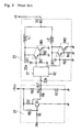
- Fig. 1 shows a speed control circuit of a brushless DC fan motor according to a first embodiment of the present invention.
- numeral 11 denotes a speed control circuit of a brushless DC fan motor (circuit) 22.
- a two-phase motor 32 is shown here.
- Symbols +V and +Vcc denote a power source for driving the motor and the speed control circuit, respectively.
- the above brushless DC fan motor 22 comprises field coils L1 and L2, switching elements SW1 and SW2, Zener diodes ZD1 and ZD2, resistors R1 to R4, a diode D1 and a drive circuit 22a.
- the field coils L1 and L2 are mounted on a stator (not shown), and electrified in an alternately switching manner to form the rotating magnetic field by the switching elements SW1 and SW2 which are alternately turned ON/OFF by the control signal from the drive circuit 22a.
- a rotor (not shown) is rotated by rotating a permanent magnet mounted thereon following the above rotating magnetic field.
- the position signals S 1 and S2 from a sensor to detect the position of rotation of the above rotor (the permanent magnet), for example, a Hall element, are inputted in the drive circuit 22a as the timing signal of switching and electrifying the field coils L1 and L2.
- the speed control circuit 21 comprises resistors R11 to R18, capacitors C1-C3, and a differential amplifier AMP.
- the speed control circuit 21 either validates or invalidates the control signal to the switching elements SW1 and SW2 of the motor 22 in the drive circuit 22a by the voltage level of the output signal therefrom.
- the speed control circuit 21 validates the above control signal when the voltage level Vb of the output terminal OUT (a control input terminal 22b of the drive circuit 22a) is less than a predetermined value (the L-level). As a result, the switching elements SW1 and SW2 are alternately turned ON/OFF. When the voltage level Vb is not less than the predetermined value (the H-level), the speed control circuit invalidates the above control signal, and turns off the switching elements SW1 and SW2.
- the speed control circuit 11 will be described below in detail.
- the differential amplifier AMP is linear in the input-output characteristic and easy in setting the rise characteristic (the amplification degree) of a desired gradient, and comprises an operational amplifier.
- the voltage signal Vi for controlling the rotational speed of the motor which is inputted in an input terminal IN is inputted in an inverting input terminal - of the differential amplifier (the operational amplifier) AMP via the resistor R13.
- the reference voltage signal Va with the voltage level set by the resistance voltage dividers (the resistors R11 and R12) connected between the above power source +Vcc and the ground is inputted in a non-inverting input terminal + of the differential amplifier AMP via the resistor R14.
- the above control voltage signal Vi is the voltage signal with the level thereof continuously changed according to the temperature in a housing of an OA appliance, for example, the temperature detecting output voltage signal by a thermistor (not shown).
- the reference voltage signal Va is the voltage corresponding to the preset temperature of detection, in other words, the voltage corresponding to the minimum rotational speed, and the minimum rotational speed of the motor 22 corresponding to the predetermined temperature of detection is set by the set value of this voltage.
- the resistor R15 is a resistor to set the amplification degree (the gradient of the rise characteristic) of the differential amplifier AMP, in other words, the rate of change of the rotational speed of the motor 22 together with the resistor R13, and connected by the inverting input terminal - and the output terminal of the differential amplifier AMP.
- the resistors R16 and R17 are resistors to set the voltage of the control input terminal 22b of the drive circuit 22a at a predetermined voltage level.
- the output signal Vo of the speed control circuit 21 controls the voltage level Vb of the output terminal OUT in a predetermined range with the voltage set by the above resistors R16 and R17 as the reference.
- the resistors R13 and R14 are set to be the same resistance. Symbols R13 and R14 also denote each resistance thereof, and symbols Vi and Va also denote each voltage (level) thereof.
- Vb -Va (R13/R15) ⁇ Vi + Va (R13/R15)
- the resistor R18 is inserted between an output terminal o of the differential amplifier AMP and the above control input terminal 22b in order to finely adjust the voltage level Vb of the control input terminal 22b of the drive circuit 22a, and is valid in finely adjusting the rotational speed of the motor.
- the capacitor C1 and the capacitor C2 are capacitors for removing noise which are inserted between the inverting input terminal - of the differential amplifier AMP and the ground, and between the non-inverting input terminal + of the differential amplifier AMP and the ground, respectively, and are effective to obtain the stable rotational speed.
- the capacitor C3 is a smoothing capacitor connected between the control input terminal 22b of the drive circuit 22a and the ground.
- the capacitor C3 is not essential in the speed control circuit 11 in accordance with the present invention.
- the PWM signal can be used for the input signal if this capacitor is added to the speed control circuit.
- the differential amplifier AMP outputs the voltage signal which is obtained by amplifying the difference in the voltage level between the control voltage signal Vi and the reference voltage signal Va at the amplification degree set by the resistors R13 and R15.
- the output voltage Vo of the differential amplifier AMP is reverse in polarity to the control voltage signal Vi (refer to the formula (1) above).
- the switching elements SW1 and SW2 of the motor 22 are alternately turned ON/OFF, the field coils L1 and L2 are alternately electrified, and the driving force is given to the rotor (not shown).
- the motor 22 is started or accelerated, and the radiation of heat in the housing is started or increased so as to drop the temperature in the housing.
- the switching elements SW1 and SW2 of the motor 22 are turned off, the electrification to the field coils L1 and L2 is shut off, and the driving force on the rotor is removed.
- the rotor is subjected to the inertial rotation, i.e., the decelerated rotation, the radiation of heat in the housing is gradually reduced, and soon, the rotor is stopped, and the heat radiation is completed.
- the field coils L1 and L2 are alternately electrified, and the driving force is given to the rotor, and the rotor is started or accelerated. As a result, heat is started to be radiated outside of the housing, or the radiation is increased, and the temperature in the housing is dropped. These operations are repeated to efficiently adjust the temperature in the housing to be within a predetermined range.
- the speed of the motor 22 can be accurately controlled without using any PWM signal for the input signal, and the temperature in the housing can be efficiently adjusted.
- the above embodiment describes a case in which the speed of the brushless DC fan motor is controlled by detecting the temperature, but the brushless DC fan motor may be controlled by other physical quantities including the humidity and the concentration of the smoke or the gas.
- the speed control circuit of the brushless DC fan motor in accordance with the present invention has advantages in that any expensive elements or circuits of the prestage are unnecessary, the motor speed can be controlled at a low cost with high accuracy, and the temperature in the housing can be efficiently adjusted particularly when the speed control circuit is used for radiating the heat in electronic appliances.
- the minimum rotational speed, the rate of change of the rotational speed, the fine adjustment of the rotational speed, and the stable rotational speed can be realized by a simple means by adding resistors and/or capacitors, or setting these values,
- the PWM signal can be used for the input signal.
Landscapes
- Engineering & Computer Science (AREA)
- Power Engineering (AREA)
- Control Of Motors That Do Not Use Commutators (AREA)
- Control Of Positive-Displacement Air Blowers (AREA)
Abstract
Description
Claims (6)
- A speed control circuit of a brushless DC fan motor which is driven by a drive circuit, and controlled in the rotational speed thereof by controlling the voltage of a control input terminal of the drive circuit comprising:wherein the differential amplifier is linear in the input-output characteristic, and can set a rise characteristic of a desired gradient, and give the voltage signal from the output terminal of the differential amplifier to the control input terminal of the drive circuit.a differential amplifier in which the voltage signal for controlling the speed is inputted in a first input terminal and the reference voltage signal is inputted in a second input terminal,
- A speed control circuit of a brushless DC fan motor according to Claim 1, wherein the reference voltage signal of the differential amplifier is given from a resistance voltage division point of a resistance voltage divider connected between a power source for driving the circuit and the ground, and the resistance of the resistance voltage divider is set to be an appropriate value in order to obtain a desired minimum rotational speed.
- A speed control circuit of a brushless DC fan motor according to Claim 1 or Claim 2, wherein the voltage signal for controlling the speed is inputted in the first input terminal of the differential amplifier via a first resistor for setting the amplification degree, a second resistor for setting the amplification degree is connected between the first input terminal and the output terminal of the differential amplifier, a desired amplification degree is obtained for the differential amplifier by suitably setting the resistance of the first and second resistors for setting the amplification degree, and a desired rate of change in the rotational speed is set.
- A speed control circuit of a brushless DC fan motor according to any one of Claims 1 to 3, wherein the first input terminal and the second input terminal of the differential amplifier are grounded individually via a capacitor.
- A speed control circuit of a brushless DC fan motor according to any one of Claims 1 to 4, wherein the voltage signal from the output terminal of the differential amplifier is given to the control input terminal of the drive circuit via a resistor for finely adjusting the rotational speed.
- A speed control circuit of a brushless DC fan motor according to any one of Claims 1 to 5, wherein a voltage signal transmission line from the output terminal of the differential amplifier to the control input terminal of the drive circuit is grounded at a desired point via a capacitor.
Applications Claiming Priority (2)
| Application Number | Priority Date | Filing Date | Title |
|---|---|---|---|
| JP2001191385 | 2001-06-25 | ||
| JP2001191385A JP2003003990A (en) | 2001-06-25 | 2001-06-25 | Speed controller for brushless direct current fan motor |
Publications (2)
| Publication Number | Publication Date |
|---|---|
| EP1271759A2 true EP1271759A2 (en) | 2003-01-02 |
| EP1271759A3 EP1271759A3 (en) | 2003-12-17 |
Family
ID=19030018
Family Applications (1)
| Application Number | Title | Priority Date | Filing Date |
|---|---|---|---|
| EP02405534A Withdrawn EP1271759A3 (en) | 2001-06-25 | 2002-06-25 | Speed control circuit for a brushless DC motor |
Country Status (4)
| Country | Link |
|---|---|
| US (2) | US20020197068A1 (en) |
| EP (1) | EP1271759A3 (en) |
| JP (1) | JP2003003990A (en) |
| CN (1) | CN1407711A (en) |
Cited By (1)
| Publication number | Priority date | Publication date | Assignee | Title |
|---|---|---|---|---|
| WO2005008878A1 (en) * | 2003-07-22 | 2005-01-27 | Sergio Adolfo Maiocchi | System for operating dc motors and power converters |
Families Citing this family (46)
| Publication number | Priority date | Publication date | Assignee | Title |
|---|---|---|---|---|
| MXPA02010777A (en) * | 2000-05-03 | 2003-03-27 | Horton Inc | A cooling system with brushless dc ring motor fan. |
| TWM243854U (en) * | 2003-02-24 | 2004-09-11 | Sunonwealth Electr Mach Ind Co | Speed control circuit for a brushless DC motor |
| JP2004364492A (en) | 2003-05-09 | 2004-12-24 | Sanyo Electric Co Ltd | Motor drive device and air conditioner |
| TW579123U (en) * | 2003-06-26 | 2004-03-01 | Delta Electronics Inc | Over spec protective device for DC motor |
| TW200400695A (en) * | 2003-07-28 | 2004-01-01 | Asia Vital Components Co Ltd | Pulse width modulation conversion control system of heat dissipation fan |
| CN1305214C (en) * | 2003-08-27 | 2007-03-14 | 建准电机工业股份有限公司 | Speed Control Circuit of Brushless DC Motor |
| US7089128B2 (en) * | 2004-09-24 | 2006-08-08 | Asia Vital Component Co., Ltd. | Control circuit of a DC fan motor for start with high voltage and high rotational speed with low voltage |
| CN100446402C (en) * | 2004-10-08 | 2008-12-24 | 鸿富锦精密工业(深圳)有限公司 | DC fan start circuit |
| CN100377491C (en) * | 2004-10-30 | 2008-03-26 | 鸿富锦精密工业(深圳)有限公司 | DC fan self-starting circuit |
| DE502006003009D1 (en) * | 2005-02-24 | 2009-04-16 | Ebm Papst St Georgen Gmbh & Co | METHOD FOR OPERATING A TWO-WAY ELECTRONICALLY COMMUTED ENGINE, AND MOTOR FOR CARRYING OUT SUCH A METHOD |
| TWI282208B (en) * | 2005-05-19 | 2007-06-01 | Delta Electronics Inc | Fan control device and method |
| US7621460B2 (en) * | 2005-09-29 | 2009-11-24 | Emc Corporation | Data storage system having cooling fan speed protection |
| CN100395955C (en) * | 2005-07-29 | 2008-06-18 | 鸿富锦精密工业(深圳)有限公司 | DC fan start circuit |
| JP2007068348A (en) * | 2005-08-31 | 2007-03-15 | Sanyo Electric Co Ltd | Motor speed control circuit |
| CN1928762A (en) * | 2005-09-09 | 2007-03-14 | 鸿富锦精密工业(深圳)有限公司 | Fan control circuit |
| CN100433538C (en) * | 2005-11-01 | 2008-11-12 | 建准电机工业股份有限公司 | PWM motor drive circuit |
| US7170242B1 (en) * | 2005-11-16 | 2007-01-30 | Sunonwealth Electric Machine Industry Co., Ltd. | Pulse-width-modulation motor drive circuit |
| US20070133955A1 (en) * | 2005-12-09 | 2007-06-14 | Wen Fuang Hsu | Fan Speed Control Circuit Simultaneously Controlled By Temperature And PWM |
| JP4801773B2 (en) * | 2007-03-30 | 2011-10-26 | 新電元工業株式会社 | Brushless motor, brushless motor control system, and brushless motor control method |
| CN101290524B (en) * | 2007-04-20 | 2011-07-27 | 富准精密工业(深圳)有限公司 | Fan circuit |
| EP2001119B1 (en) | 2007-06-06 | 2014-07-30 | Marko Schwoch | Control circuit for a DC motor |
| US20090108790A1 (en) * | 2007-10-31 | 2009-04-30 | Wen-Hui Chen | Control structure of an electric fan |
| US9207023B2 (en) | 2007-12-18 | 2015-12-08 | Sandia Corporation | Heat exchanger device and method for heat removal or transfer |
| US8228675B2 (en) * | 2007-12-18 | 2012-07-24 | Sandia Corporation | Heat exchanger device and method for heat removal or transfer |
| US8988881B2 (en) | 2007-12-18 | 2015-03-24 | Sandia Corporation | Heat exchanger device and method for heat removal or transfer |
| US7863849B2 (en) * | 2008-02-29 | 2011-01-04 | Standard Microsystems Corporation | Delta-sigma modulator for a fan driver |
| US9005417B1 (en) | 2008-10-01 | 2015-04-14 | Sandia Corporation | Devices, systems, and methods for microscale isoelectric fractionation |
| US8241008B2 (en) * | 2009-02-26 | 2012-08-14 | Standard Microsystems Corporation | RPM controller using drive profiles |
| CN101582679B (en) * | 2009-06-26 | 2010-12-08 | 哈尔滨工业大学 | Hybrid Power Converter with Linear Output and PWM Output |
| CN102052341A (en) * | 2009-10-30 | 2011-05-11 | 鸿富锦精密工业(深圳)有限公司 | Fan control system |
| TWI451687B (en) * | 2009-12-15 | 2014-09-01 | Hon Hai Prec Ind Co Ltd | Fan controlling system |
| CN102208889A (en) * | 2010-03-29 | 2011-10-05 | 美商恩杰有限公司 | Speed adjusting method for DC motor double-power supply |
| US8962346B2 (en) | 2010-07-08 | 2015-02-24 | Sandia Corporation | Devices, systems, and methods for conducting assays with improved sensitivity using sedimentation |
| US9795961B1 (en) | 2010-07-08 | 2017-10-24 | National Technology & Engineering Solutions Of Sandia, Llc | Devices, systems, and methods for detecting nucleic acids using sedimentation |
| US8945914B1 (en) | 2010-07-08 | 2015-02-03 | Sandia Corporation | Devices, systems, and methods for conducting sandwich assays using sedimentation |
| US9261100B2 (en) | 2010-08-13 | 2016-02-16 | Sandia Corporation | Axial flow heat exchanger devices and methods for heat transfer using axial flow devices |
| CN102400933A (en) * | 2010-09-17 | 2012-04-04 | 鸿富锦精密工业(深圳)有限公司 | Fan drive circuit |
| CN102454618A (en) * | 2010-10-19 | 2012-05-16 | 鸿富锦精密工业(深圳)有限公司 | Fan control system and method |
| US9244065B1 (en) | 2012-03-16 | 2016-01-26 | Sandia Corporation | Systems, devices, and methods for agglutination assays using sedimentation |
| JP2014023388A (en) * | 2012-07-23 | 2014-02-03 | Toshiba Corp | Motor drive circuit and motor drive system |
| CN102852843B (en) * | 2012-08-31 | 2014-10-08 | 北京机械设备研究所 | Temperature-controlled speed-regulating circuit for direct-current fan |
| TWI473416B (en) | 2012-09-14 | 2015-02-11 | Amtek Semiconductor Co Ltd | Motor driving device with speed control and driving method thereof |
| CN102996485B (en) * | 2012-11-30 | 2015-10-21 | 杭州顿力电器有限公司 | The isolation characteristic alignment circuit of electronic control type fan of outer rotor and speed regulating method |
| CN104467574A (en) * | 2013-09-23 | 2015-03-25 | 深圳市海洋王照明工程有限公司 | Speed control circuit of temperature control motor |
| CN104009681A (en) * | 2014-06-05 | 2014-08-27 | 惠州市蓝微电子有限公司 | Control method for drive control system of single-phase brushless direct-current motor |
| WO2024141929A1 (en) * | 2022-12-28 | 2024-07-04 | Atomberg Technologies Private Limited | A regulator detection system for a bldc fan and method thereof |
Family Cites Families (16)
| Publication number | Priority date | Publication date | Assignee | Title |
|---|---|---|---|---|
| US4337497A (en) * | 1980-10-23 | 1982-06-29 | Honeywell Information Systems Inc. | Device for detecting the direction and change of rotational speed of a rotating element |
| US4506199A (en) * | 1982-12-28 | 1985-03-19 | Asche Bernard J | Agricultural fan control system |
| US5245256A (en) * | 1991-02-15 | 1993-09-14 | Seagate Technology, Inc. | Closed loop control of a brushless DC motor at nominal speed |
| US5234050A (en) * | 1991-09-06 | 1993-08-10 | Interdynamics, Inc. | Automatic climate control system |
| US5197858A (en) * | 1991-10-23 | 1993-03-30 | Delta Electronics, Inc. | Thermal control variable speed DC brushless fan |
| US5457766A (en) * | 1992-05-23 | 1995-10-10 | Samsung Electronics Co., Ltd. | Fan speed control circuit |
| MY112702A (en) * | 1992-10-30 | 2001-08-30 | Sony Corp | Reproducing circuit for a magnetic head. |
| US5534854A (en) * | 1995-07-10 | 1996-07-09 | Bradbury; Rod J. | Fan failure alert for electronic equipment |
| US6040668A (en) * | 1996-11-14 | 2000-03-21 | Telcom Semiconductor, Inc. | Monolithic fan controller |
| US5991700A (en) * | 1997-10-15 | 1999-11-23 | Sherwood Services, A.G. | EMI stability indicator for tympanic thermometer |
| US5929581A (en) * | 1997-10-22 | 1999-07-27 | Hewlett-Packard Company | Proportional integral fan controller for computer |
| GB2333378B (en) * | 1998-01-16 | 1999-12-08 | Hsieh Hsin Mao | PWN control circuit for a DC brushless fan |
| US6285146B1 (en) * | 1998-08-07 | 2001-09-04 | Nidec America Corporation | Apparatus and method of regulating the speed of a brushless DC motor |
| US6188187B1 (en) * | 1998-08-07 | 2001-02-13 | Nidec America Corporation | Apparatus and method of regulating the speed of a DC brushless motor |
| US6135718A (en) * | 1999-03-25 | 2000-10-24 | System General Corporation | Interface apparatus for fan monitoring and control |
| US6385395B1 (en) * | 2001-02-14 | 2002-05-07 | Sunonwealth Electric Machine Industry Co., Ltd. | Fan motor with its speed controlled by operating periods of a pulse wave |
-
2001
- 2001-06-25 JP JP2001191385A patent/JP2003003990A/en active Pending
-
2002
- 2002-06-25 EP EP02405534A patent/EP1271759A3/en not_active Withdrawn
- 2002-06-25 US US10/178,732 patent/US20020197068A1/en not_active Abandoned
- 2002-06-25 CN CN02144386A patent/CN1407711A/en active Pending
-
2004
- 2004-02-23 US US10/782,809 patent/US6879120B2/en not_active Expired - Fee Related
Cited By (3)
| Publication number | Priority date | Publication date | Assignee | Title |
|---|---|---|---|---|
| WO2005008878A1 (en) * | 2003-07-22 | 2005-01-27 | Sergio Adolfo Maiocchi | System for operating dc motors and power converters |
| US7659678B2 (en) | 2003-07-22 | 2010-02-09 | Maiocchi Sergio A | System for operating DC motors and power converters |
| US8587238B2 (en) | 2003-07-22 | 2013-11-19 | Sergio A. Maiocchi | System for operating DC motors and power converters |
Also Published As
| Publication number | Publication date |
|---|---|
| US20020197068A1 (en) | 2002-12-26 |
| CN1407711A (en) | 2003-04-02 |
| JP2003003990A (en) | 2003-01-08 |
| US20040164692A1 (en) | 2004-08-26 |
| US6879120B2 (en) | 2005-04-12 |
| EP1271759A3 (en) | 2003-12-17 |
Similar Documents
| Publication | Publication Date | Title |
|---|---|---|
| US6879120B2 (en) | Speed control circuit of brushless DC fan motor | |
| US6779981B2 (en) | Fan control system using a microcontroller | |
| US5589751A (en) | Sensorless switched reluctance motor | |
| US6703803B2 (en) | Fan motor driving circuit | |
| US20040247449A1 (en) | Fan control system using a microcontroller | |
| US6674257B2 (en) | Current limiting circuit of brushless DC fan motor | |
| US6815916B2 (en) | Speed-control drive circuit for a D.C. brushless fan motor | |
| US6385395B1 (en) | Fan motor with its speed controlled by operating periods of a pulse wave | |
| US8203296B2 (en) | BLDC motors | |
| JP2789450B2 (en) | A device that drives a position adjustment member with a step motor | |
| US6515447B2 (en) | Fan motor with variable frequency/constant speed control | |
| KR20050077794A (en) | Motor driving apparatus, integrated circuit, and motor driving method | |
| KR20110133438A (en) | Drive device and driving method of blower | |
| JP4077995B2 (en) | Motor control device with soft start function for brushless motor | |
| JP4649934B2 (en) | Brushless DC motor control device and ceiling fan equipped with the same | |
| JP2002010667A (en) | DC motor rotation detection device and rotation control device | |
| JP2002101683A (en) | Phase angle control method of brushless dc motor | |
| US9344017B2 (en) | Driving circuit and driving method thereof | |
| JP4097320B2 (en) | Fan motor drive circuit | |
| KR20020032941A (en) | Low price type senseless detection circuit for motor | |
| JP2884584B2 (en) | DC fan | |
| KR930005383B1 (en) | Control circuit of 2-phase brushless motor | |
| JPS6011758Y2 (en) | Brushless motor forward/reverse rotation control device | |
| JP2024140992A (en) | MOTOR DRIVE CONTROL DEVICE, ACTUATOR, AND MOTOR DRIVE CONTROL METHOD | |
| JPS5836188A (en) | Brushless motor drive circuit |
Legal Events
| Date | Code | Title | Description |
|---|---|---|---|
| PUAI | Public reference made under article 153(3) epc to a published international application that has entered the european phase |
Free format text: ORIGINAL CODE: 0009012 |
|
| AK | Designated contracting states |
Kind code of ref document: A2 Designated state(s): AT BE CH CY DE DK ES FI FR GB GR IE IT LI LU MC NL PT SE TR |
|
| AX | Request for extension of the european patent |
Free format text: AL;LT;LV;MK;RO;SI |
|
| RTI1 | Title (correction) |
Free format text: SPEED CONTROL CIRCUIT FOR A BRUSHLESS DC MOTOR |
|
| PUAL | Search report despatched |
Free format text: ORIGINAL CODE: 0009013 |
|
| AK | Designated contracting states |
Kind code of ref document: A3 Designated state(s): AT BE CH CY DE DK ES FI FR GB GR IE IT LI LU MC NL PT SE TR |
|
| AX | Request for extension of the european patent |
Extension state: AL LT LV MK RO SI |
|
| 17P | Request for examination filed |
Effective date: 20040605 |
|
| AKX | Designation fees paid |
Designated state(s): DE GB |
|
| STAA | Information on the status of an ep patent application or granted ep patent |
Free format text: STATUS: THE APPLICATION HAS BEEN WITHDRAWN |
|
| 18W | Application withdrawn |
Effective date: 20080626 |