EP1271726A2 - Method for producing spark plug - Google Patents
Method for producing spark plug Download PDFInfo
- Publication number
- EP1271726A2 EP1271726A2 EP02254501A EP02254501A EP1271726A2 EP 1271726 A2 EP1271726 A2 EP 1271726A2 EP 02254501 A EP02254501 A EP 02254501A EP 02254501 A EP02254501 A EP 02254501A EP 1271726 A2 EP1271726 A2 EP 1271726A2
- Authority
- EP
- European Patent Office
- Prior art keywords
- glaze
- powder
- layer
- composition
- mol
- Prior art date
- Legal status (The legal status is an assumption and is not a legal conclusion. Google has not performed a legal analysis and makes no representation as to the accuracy of the status listed.)
- Granted
Links
Images


Classifications
-
- H—ELECTRICITY
- H01—ELECTRIC ELEMENTS
- H01T—SPARK GAPS; OVERVOLTAGE ARRESTERS USING SPARK GAPS; SPARKING PLUGS; CORONA DEVICES; GENERATING IONS TO BE INTRODUCED INTO NON-ENCLOSED GASES
- H01T13/00—Sparking plugs
- H01T13/52—Sparking plugs characterised by a discharge along a surface
-
- H—ELECTRICITY
- H01—ELECTRIC ELEMENTS
- H01T—SPARK GAPS; OVERVOLTAGE ARRESTERS USING SPARK GAPS; SPARKING PLUGS; CORONA DEVICES; GENERATING IONS TO BE INTRODUCED INTO NON-ENCLOSED GASES
- H01T21/00—Apparatus or processes specially adapted for the manufacture or maintenance of spark gaps or sparking plugs
- H01T21/02—Apparatus or processes specially adapted for the manufacture or maintenance of spark gaps or sparking plugs of sparking plugs
-
- Y—GENERAL TAGGING OF NEW TECHNOLOGICAL DEVELOPMENTS; GENERAL TAGGING OF CROSS-SECTIONAL TECHNOLOGIES SPANNING OVER SEVERAL SECTIONS OF THE IPC; TECHNICAL SUBJECTS COVERED BY FORMER USPC CROSS-REFERENCE ART COLLECTIONS [XRACs] AND DIGESTS
- Y10—TECHNICAL SUBJECTS COVERED BY FORMER USPC
- Y10T—TECHNICAL SUBJECTS COVERED BY FORMER US CLASSIFICATION
- Y10T29/00—Metal working
- Y10T29/49—Method of mechanical manufacture
- Y10T29/49229—Prime mover or fluid pump making
- Y10T29/49231—I.C. [internal combustion] engine making
Definitions
- This invention relates to a spark plug.
- a spark plug used for ignition of an internal engine of such as automobiles generally comprises a metal shell to which a ground electrode is fixed, an insulator made of alumina ceramics, and a center electrode which is disposed inside the insulator.
- the insulator projects from the rear opening of the metal shell in the axial direction.
- a terminal metal fixture is inserted into the projecting part of the insulator and is connected to the center electrode via a conductive glass seal layer which is formed by a glass sealing procedure or a resistor.
- a high voltage is applied to the terminal metal fixture to cause a spark over the gap between the ground electrode and the center electrode.
- No. 106234/1999 refers to the improved insulation resistance by joint addition of alkaline component in the glaze containing Si or B as vitreous skeletons, but does not pay sufficient attention to cancellation of difference in the linear expansion coefficient from the alumina based ceramics as a ceramics composing the insulator, and a level of the improved insulation resistance is not necessarily enough.
- the glaze not especially containing Pb for lessening the difference in the linear expansion coefficient from the alumina based ceramics, it is useful to increase oxide components as Si or Zn, but if employing such a composition, the dilatometric softening point of the glaze increases, and the fluidity when baking the glaze easily lacks.
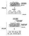
- non-adjusted glaze powder having the same composition as an average composition of a final glaze layer as shown in Fig. 2A
- the dilatometric softening point of the glaze goes up, so that the fluidity at glaze-baking especially lacks, and air bubbles might be caused to remain in the glaze layer.
- the above mentioned effect is particularly remarkably exhibited when such a glaze layer is formed where the dilatometric softening point of the non-adjusted glaze is easy to go up, and the Pb containing rate is 1 mol% or less in terms of PbO.
- the composition of the glaze has the vitreous skeleton being main of SiO 2 , the containing rate of the Si compound derived therefrom gives large influences to the dilatometric softening point of the glaze composition and the values of the liner expansion coefficient.
- ZnO is excellent in lowering the dilatometric softening point of the glaze by appropriately mixing it, reducing the liner expansion coefficient of the glaze, and lessening the difference of the liner expansion coefficient from the insulator composed of the alumina based ceramics.
- the composition of the adjusted glaze powder powders that is, the respective compositions of the element glaze powder powders and the mixing ratios therewith
- the liner expansion coefficient of the glaze layer 85 x 10 -7 /°C.
- the liner expansion coefficient of the glaze layer is made less than 50 x 10 -7 /°C, it is difficult to determine the composition of the adjusted glaze powder powders such that the fluidity at glaze-baking is sufficiently improved.
- Any one of the followings is prepared as a substance having a lower linear expansion coefficient than that of the main glaze composition and higher dilatometric softening point than that thereof.
- the element glaze powder containing the main glaze composition (referred to as “main element glaze powder” hereafter) is mixed with the element glaze powder of the sub-glaze composition (referred to as “sub-element glaze powder” hereafter) .
- the adjusted glaze powder is produced.
- the Pb component plays an important part as to adjustment of the dilatometric softening point (practically, appropriately lowering the dilatometric softening point of the glaze and securing the fluidity when baking the glaze) but in the leadless glaze, the B component (B 2 O 3 ) and the alkaline metal component have a deep relation with adjustment of the dilatometric softening point.
- the B component has a particularly convenient range for improving the glaze baking finish in relation with the content of the Si component, and if selecting this range, the fluidity when baking the glaze may be secured, and in turn the baking of the glaze is possible at relatively low temperatures, the glaze layer having an excellent and smooth baked surface is available.
- the Si component is difficult to secure the sufficient insulation property if being less than 25 mol%, and is difficult to bake the glaze if being more than 45 mol%
- the B component is less than 20 mol%
- the dilatometric softening point of the glaze rises and the baking of the glaze is difficult.
- the B component is more than 40 mol%
- crimping is easily created in the glaze.
- the Zn component is less than 5 mol%, coefficient of thermal expansion of the glaze layer is too large, and defects as crimping easily occurs in the glaze layer. Further, the Zn component works to lower the dilatometric softening point of the glaze, an if it is short, the glaze-baking is difficult.
- the Zn component exceeds 25 mol%, opacity is ready for issuing owing to devitrification.
- the total amount of the Zn component and Ba and/or Sr components is desirably 8 to 30 mol% in terms of oxide. If the total amount exceeds 30 mol%, the glaze layer will be slightly opaque. For example, on the outer surface of the insulator, visual information such as letters, figures or product numbers are printed and baked with color glazes for identifying makers and others, and owing to the slight opaqueness, the printed visual information is sometimes illegible. Or, if being less than 8 mol%, the dilatometric softening point exceedingly goes up to make the glaze baking difficult and cause bad external appearance. Thus, the total amount is more desirably 10 to 20 mol%.
- the total containing amount of alkaline metal components is 5 to 10 mol%. Being less than 5 mol%, the dilatometric softening point of the glaze goes up, and the glaze-baking might be impossible. On the other hand, being more than 10 mol%, the insulation property of the glaze goes down to probably spoil the anti-flashover. It is desirable to set the rate of the K component of the alkaline metal components of Na, K and Li in the mol% in terms of oxide to be 0.4 ⁇ K/(Na + K + Li) ⁇ 0.8. Thereby, the effect of improving the insulation property is more heightened. Only, if the value of K/(Na + K + Li) is less than 0.4, the effect thereof might be insufficient.
- the value of K/(Na + K + Li) is set to be 0.8 or less for securing the fluidity at the glaze-baking, and signifies that the alkaline metal component other K is jointly added in the range of the rest being 0.2 or more ( ⁇ 0.6).
- the value of K/ (Na + K + Li) is desirably adjusted within the range of 0.5 to 0.7.
- the rate of Li is less than 0.2, the heat expansion coefficient becomes too large as compared with the alumina substrate. As a result, the crazing may be easily produced to make the finished glaze-baking surface insufficient.
- the rate of Li component exceeds 0.5, because the Li ion is of a comparatively high degree of immigration among the alkaline metal ions, this may give an adverse influence to the insulation property of the glaze layer. It is preferable that the value of Li/ (Na + K + Li) is adjusted in the range of 0.3 to 0.45.
- the above mentioned glaze composition can secure the fluidity at glaze-baking under a better condition by containing one kind or more of Mo, W, Ni, Co, Fe and Mn 0.5 to 5 mol% in total in terms of MoO 3 , WO 3 , Ni 3 O 4 , Co 3 O 4 , Fe 2 O 3 and MnO 2 , respectively. If being less than 0.5 mol%, it is insufficient to accomplish an enough effect which improves the fluidity at glaze-baking, while being more than 5 mol%, the dilatometric softening point of the glaze exceedingly goes up, and the glaze-baking is difficult or impossible.
- the main element glaze powder when the main element glaze powder is preferentially fused at glaze-baking, it is delayed in going into a molten phase of the sub-element glaze powder, so that a time when a fused phase high in the fluidity is formed is extended. Consequently, air bubbles held among glaze powders are accelerated to get out, and the glaze layer excellent in the chipping resistance is made available.
- the mixing amount of the sub-element glaze powder in the adjusted glaze powders is desirably adjusted to be in a range of 5 to 30 weight%. Being less than 5 weight%, the linear expansion coefficient of the produced glaze layer is too large, and the difference of the linear expansion coefficient from the insulator made of the alumina based ceramic is large, so that defects as crazing easily occurs in the produced glaze layer.
- the above mentioned effect by mixing the sub-element glaze powder cannot be accomplished, and if exceeding 30 weight%, the fluidity at the glaze-baking is worsened, so that the effect of removing air bubbles cannot be fully exhibited.
- the linear expansion coefficient preferably ranges 50 x 10 -7 /°C to 80 x 10 -7 /°C. Accordingly, for the sub-glaze composition, it is necessary to employ a linear expansion coefficient smaller than said range, and if employing a linear expansion coefficient less than 50 x 10 -7 /°C, this is desirable in view of reducing average linear expansion coefficient in the produced glaze layer and restraining occurrence of defects as crimping.
- the Si component is less than 60 mol%, the B component exceeds 25 mol%, or the total amount of the alkaline metal components is more than 8 mol%, the linear expansion coefficient of the finally produced glaze layer cannot be fully lowered, and defects as crazing are easy to occur in the glaze layer.
- the Si component is more than 80 mol%, or the B component is less than 10 mol%, or the total amount of the alkaline metal components is less than 4 mol%, the transparency of the glaze layer is easily spoiled, and the fluidity of the fused phase occurring at glaze-baking is worsened depending on the mixing amount, so that the effect of the invention cannot be fully exhibited.
- the Zn component is less than 45 mol%, or the B component exceeds 50 mol%, the linear expansion coefficient of the finally produced glaze layer cannot be fully lowered, and defects as crazing are easy to occur in the glaze layer.
- the Zn component is more than 65 mol%, or the B component is less than 30 mol%, the transparency of the glaze layer is easily spoiled, the fluidity of the fused phase occurring at the glaze-baking is worsened depending on the mixing amount, so that the effect of the invention cannot be fully exhibited.
- Fig. 3 shows an example of the spark plug applied by the invention.
- the spark plug 100 has a cylindrical metal shell 1, an insulator 2 fitted in the inside of the metal shell 1 with its tip 21 projecting from the front end of the metal shell 1, a center electrode 3 disposed inside the insulator 2 with its ignition part 31 of a precious metal formed at the tip thereof, and a ground electrode 4 with its one end welded to the metal shell 1 and the other end bent inward such that a side of this end may face the tip of the center electrode 3.
- the ground electrode 4 has an ignition part 32 which faces the ignition part 31 to make a spark gap g between the facing ignition parts 32.
- the metal shell 1 is formed to be cylindrical of a metal such as a low carbon steel. It has a thread 7 and a hexagonal nut portion 1e therearound for screwing the spark plug 100 into an engine block (not shown).
- the insulator 2 has a through-hole 6 penetrating in the axial direction.
- a terminal fixture 13 is fixedly inserted in one end of the through-hole 6, and the center electrode 3 is fixedly inserted in the other end.
- a resistor 15 is disposed in the through-hole 6 between the terminal metal fixture 13 and the center electrode 3. The resistor 15 is electrically connected at both ends thereof to the center electrode 3 and the terminal metal fixture 13 via the conductive glass seal layers 16 and 17, respectively.
- the insulator 2 has a through-hole 6 for inserting the center electrode 3 along in the axial direction thereof , and is as a whole composed of an alumina based ceramic sintered body.
- the insulator 2 has a projection 2e projecting outwardly, e.g., flange-like on its periphery at the middle part in the axial direction, a rear portion 2b whose outer diameter is smaller than the projecting portion 2e, a first front portion 2g in front of the projecting portion 2e, whose outer diameter is smaller than the projecting portion 2e, and a second front portion 2i in front of the first front portion 2g, whose outer diameter is smaller than the first front portion 2g.
- the rear end part of the rear portion 2b is not formed with corrugations.
- the first front portion 2g is almost cylindrical, while the second front portion 2i is tapered toward the tip 21.
- the center electrode 3 has a smaller diameter than that of the resistor 15.
- the through-hole 6 of the insulator 2 is divided into a first portion 6a (front portion) having a circular cross section in which the center electrode 3 is fitted and a second portion 6b (rear portion) having a circular cross section with a larger diameter than that of the first portion 6a.
- the terminal metal fixture 13 and the resistor 15 are disposed in the second portion 6b, and the center electrode 3 is inserted in the first portion 6a.
- the center electrode 3 has an outward projection 3c around its periphery near the rear end thereof, with which it is fixed to the electrode.
- a first portion 6a and a second portion 6b of the through-hole 6 are connected each other in the first front portion 2g, and at the connecting part, a projection receiving face 6c is tapered or rounded for receiving the projection 3c for fixing the center electrode 3.
- the first front portion 2g and the second front portion 2i of the insulator 2 connect at a connecting part 2h, where a level difference is formed on the outer surface of the insulator 2.
- the metal shell 1 has a projection 1c on its inner wall at the position meeting the connecting part 2h so that the connecting part 2h fits the projection 1c via a gasket ring 63 thereby to prevent slipping in the axial direction.
- a gasket ring 62 is disposed between the inner wall of the metal shell 1 and the outer side of the insulator 2 at the rear of the flange-like projecting portion 2e, and a gasket ring 60 is provided in the rear of the gasket ring 62.
- the space between the two gaskets 60 and 62 is filled with a filler 61 such as talc.
- the insulator 2 is inserted into the metal shell 1 toward the front end thereof, and under this condition, the rear opening edge of the metal shell 1 is pressed inward the gasket 60 to form a crimping portion 1d, and the metal shell 1 is secured to the insulator 2.
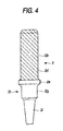
- the glaze layer 2d is formed on the surface of the insulator 2, actually as seen in Fig. 4, on the outer peripheral surface of a main body 2b.
- the glaze layer 2d desirably is smooth at a maximum height Ry being 10 ⁇ m or less in a curve of a surface roughness of the glaze layer 2d in accordance to the measurement prescribed by JIS:B0601 at the outer periphery of the base portion of the main body 2b.
- the formed thickness is 10 to 150 ⁇ m, desirably 10 to 50 ⁇ m.
- the spark plug 100 can be produced as follows.
- an alumina powder is mixed with raw material powders of a Si component, Ca component, Mg component, Ba component, and B component such that a predetermined mixing ratio is obtained in the above mentioned composition in terms of oxides after sintering, and the mixed powder is mixed with a predetermined amount of a binder (e.g., PVA) and a water to form matrix granules, so that an original figure of the insulator is prepared, and this is baked at 1400 to 1600°C.
- a binder e.g., PVA
- a glaze slurry is prepared as follows.
- raw material powders as sources of Si, Al, B, Zn, Ba, Na, Ka and Li are prepared (for example, the Si component is SiO 2 powder, the Al component is Al 2 O 3 powder, the B component is H 3 BO 3 powder, the Zn component is ZnO powder, the Ba component is BaCO 3 powder, Na is Na 2 CO 3 powder, K is K 2 CO 3 powder, and Li is Li 2 CO 3 powder) .
- these substances are compounded and mixed such that the main and sub-glaze compositions are obtained respectively .
- the mixture is heated and melted at, e.g., 1000 to 1500°C, and thrown into the water to rapidly cool for vitrification, followed by grinding into fine pulverization of average diameter being, e.g., 5 to 45 ⁇ m to be the main and sub-glaze powders .
- These powders are compounded such that the sub-glaze powders become 5 to 30 weight%, and mixed with appropriate amounts of clay mineral such as kaolin or gairome clay and organic binder, and a water group solvent is added thereto to prepare the glaze slurry.
- the adjusted glaze slurry is sprayed from a spray nozzle N to coat a required surface of the insulator 2, so that a glaze powder layer 2d' of an adjusted glaze powder is formed.
- the glaze powder layer 2d' becomes a glaze layer 2d as seen in Fig. 4.
- the main element glaze powder having a lower dilatometric softening point is early softened and melted, and then formed with a liquid phase (herein, the first glaze powder corresponds to the main element glaze powder, while the second glaze powder corresponds to the sub-element glaze powder).
- the earlier softened main element glaze powder (the first glaze powder) employs powders of the average smaller diameter (or those of larger specific surface value) than that of the sub-element glaze powder (the second glaze powder)
- the melting of the main element glaze powder can be accelerated when baking the glaze, and the fluidity at the glaze-baking can be more heightened.
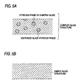
- the main glaze composition forming the main element glaze powder is uniformly mixed with the sub-glaze composition forming the sub-element glaze powder, and a simple glaze structure is produced as seen in Fig. 5B.
- a result is the same as using a non-adjusted glaze powder at the latter-half of the glaze-baking, so that the fluidity is spoiled and an enough smooth glaze layer might not be obtained (this results, for example, in bad external appearance or lowering the anti-flashover).
- the finally produced glaze layer can be, as shown in Fig. 5A, composed of the vitreous phase of a matrix glaze being the main of the glaze composition of the main element glaze powder and the dispersed glaze vitreous phase being the main of the glaze composition of the sub-element glaze powder.
- a smoother glaze layer can be realized, and beside the dispersed glaze vitreous phase plays a role of an aggregate during the glaze-baking, and such inconveniences are difficult to occur that the glaze exceedingly flows to cause the glaze to drop or become uneven.
- the average linear expansion coefficient of the glaze layer canbe more lessened than the case of using the non-adjusted glaze powder, in turn resulting to obtain an effect of more reducing the difference of the linear expansion coefficient from the insulator.
- the insulator 2 which is already coated with the glaze is set up with the metal shell 1 and a ground electrode 4, and the spark plug 100 is completed as shown in Fig. 3.
- the insulator 2 composed of alumina ceramic sintered substance embodied as shown in Fig. 3 was made through an ordinary process.
- Prepared raw materials were SiO 2 powder (purity: 99.5%), Al 2 O 3 powder (purity: 99.5%), H 3 BO 3 powder (purity: 98.5%), ZnO powder (purity: 99.5%), BaSO 3 powder (purity: 99.5%), SrO powder (purity: 99.5%), Na 2 CO 3 powder (purity: 99.5%), K 2 CO 3 powder (purity: 99%), Li 2 CO 3 powder (purity: 99%), MoO 3 powder (purity: 99%), Fe 2 O 3 powder (purity: 99%), ZrO 2 powder (purity: 99.5%), TiO 2 powder (purity: 99.5%), CaCO 3 powder (purity: 99.8%), MgO powder (purity: 99.5%), and Bi 2 O 3 powder (purity: 99%).
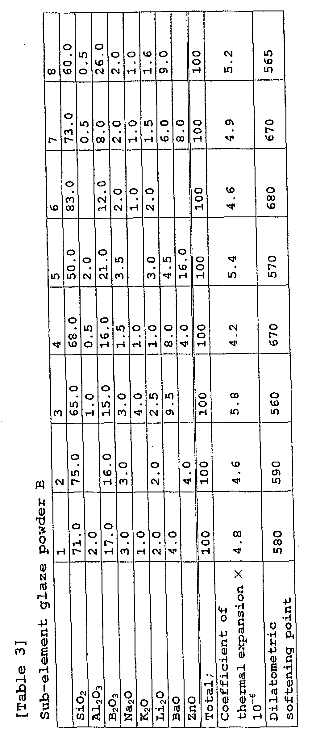
- the respective main element glaze powders were mixed with the respective sub-element glaze powders at the weight ratios shown in Tables 3 to 5 (No. 5 in Table 3 is a comparative example of mixing with no sub-element glaze powder) .
- To 100 weight parts of the mixture 3 parts by weight of New Zealand kaolin and 2 parts by weight of PVA as an organic binder were mixed, and the mixture was kneaded with 100 weight parts of the water to prepare the glaze slurry (the adjusted glaze powder).
- the above mentioned glaze slurry was sprayed on the insulator 2 from the spray nozzle, and dried to form the coated layer of the glaze slurry.
- the insulator 2 was immersed in the bath where the glaze slurry was thrown, and pulled up to form the glaze layer on the surface of the insulator 2.
- the coated thickness of the dried glaze was around 100 ⁇ m.
- the insulator 2 was subjected to the glaze-baking at 900°C for 30 minutes, and the formed state of the obtained glaze layer 2d was visually observed.
- the thermal shock resistance was evaluated as follows. The test that, the non-glaze coated part was covered with a silicone tube, kept at a constant temperature T (°C) higher than a room temperature in a chamber at high temperature, and thrown into a water at 20°C, was repeated as gradually increasing the keeping temperature, and the temperature T when cracks began in the glaze layer was measured, thereby to determine the difference T - 20°C of a limited cooling temperature.
- the chipping resistance of the glaze layer was evaluated as follows . The spark plug 100 was produced and the chip test was performed. That is, an attaching screw portion 7 of the spark plug was screwed into a threaded hole of a securing bed of the test piece, so that a main portion 2b of the insulator 2 was turned upward.
Landscapes
- Engineering & Computer Science (AREA)
- Manufacturing & Machinery (AREA)
- Spark Plugs (AREA)
- Glass Compositions (AREA)
Abstract
Description
a process of producing a plurality of kinds of element glaze powders where dilatometric softening points and linear expansion coefficient are different one another,
a process of forming a glaze powder layer by coating the surface of the insulator with the plurality of kinds of element glaze powders, and
a process of baking the glaze powder layer onto the surface of the insulator by heating the insulator so as to form the glaze layer.



| Number; | 1 | 2 | 3 | 4 | 5 | 6 | |
| A | Vitreous composition No. | A-1 | A-2 | A-3 | A-4 | A-5 | A-5 |
| Mixing ratio(%) | 93% | 75% | 96% | 65% | 93% | 93% | |
| B | Vitreous composition No. | B-1 | B-2 | B-2 | B-1 | B-1 | B-4 |
| Mixing ratio(%) | 7% | 25% | 4% | 35% | 7% | 7% | |
| C | Vitreous composition No. | - | - | - | - | - - | |
| Mixing ratio (%) | 0% | 0% | 0% | 0% | 0% | 0% | |
| D | SiO2 | 36.0 | 37.5 | 35.5 | 39.0 | 42.0 | 41.8 |
| Al2O3 | 2.0 | 2.0 | 2.0 | 2.0 | 2.0 | 1.9 | |
| B2O3 | 28.0 | 27.0 | 28.5 | 26.0 | 23.0 | 22.9 | |
| Na2O | 1.0 | 1.0 | 1.0 | 1.0 | 1.0 | 0.9 | |
| K2O | 4.5 | 4.5 | 4.5 | 4.5 | 4.5 | 4.5 | |
| Li2O | 2.0 | 2.0 | 2.0 | 2.0 | 2.0 | 1.9 | |
| BaO | 4.5 | 3.5 | 4.5 | 4.5 | 4.5 | 4.8 | |
| SrO | 1.0 | ||||||
| ZnO | 16.0 | 16.0 | 16.0 | 15.0 | 16.0 | 16.3 | |
| MoO3 | 1.0 | 1.0 | 1.0 | 1.0 | 1.0 | 1.0 | |
| Fe2O3 | |||||||
| CaO | 4.0 | 3.5 | 4.0 | 4.0 | 3.0 | 3.0 | |
| ZrO2 | 1.0 | 1.0 | 1.0 | 1.0 | 1.0 | 1.0 | |
| TiO2 | |||||||
| MgO | |||||||
| Total; | 100 | 100 | 100 | 100 | 100 | 100 | |
| K/(Na+Li+K) | 0.60 | 0.60 | 0.60 | 0.60 | 0.60 | 0.61 | |
| Li/(Na+Li+K) | 0.27 | 0.27 | 0.27 | 0.27 | 0.27 | 0.26 | |
| ZnO+BaO/SrO | 20.5 | 20.5 | 20.5 | 19.5 | 20.5 | 21.1 | |
| Linear expansion coefficient × 10-6 | 6.70 | 6.50 | 6.70 | 6.30 | 7.00 | 6.30 | |
| Dilatometric softening point | 575 | 580 | 570 | 605 | 570 | 605 | |
| External appearance | ○ | ○ | ○ | Δ E | ○ | Δ E | |
| Thermal shock resistance (Crack appearing temp. ΔT) | 240°C | 250°C | 200°C | 240°C | 230°C | 210°C | |
| Chipping resistance | 44° | 46° | 36° | 34° | 44° | 38° | |
| Void number (pieces) in the | 15 | 10 | 25 | 35 | 10 | 30 | |
| Special remark; | |||||||
| (Unit mol% : * is out of the inventive range;) A : Main element glaze powder A; B : Sub-element glaze powder B; C : Sub-element glaze powder C; D : Composition of the glaze powders after mixing E : A little insufficient glaze-melting |
| Number; | 7 | 8 | 9* | 10 | 11* | 12 | |
| A | Vitreous composition No. | A-5 | A-5 | A-6 | A-7 | A-8 | A-9 |
| Mixing ratio (%) | 93% | 93% | 100% | 92% | 100% | 75% | |
| B | Vitreous composition No. | B-6 | B-7 | - | - | - | B-1 |
| Mixing ratio(%) | 7% | 7% | 0% | 0% | 0% | 15% | |
| C | Vitreous composition No. | - | - | - | C-9 | - | C-9 |
| Mixing ratio (%) | 0% | 0% | 0% | 8% | 0% | 10% | |
| D | SiO2 | 42.8 | 42.1 | 42.0 | 28.0 | 28.0 | 37.0 |
| Al2O3 | 1.9 | 1.9 | 2.0 | 2.0 | 2.0 | 2.0 | |
| B2O3 | 22.7 | 22.4 | 23.0 | 37.0 | 37.0 | 27.0 | |
| Na2O | 0.9 | 0.9 | 1.0 | 1.0 | 1.0 | 1.0 | |
| K2O | 4.5 | 4.5 | 4.5 | 4.5 | 4.5 | 4.5 | |
| Li2O | 2.0 | 2.0 | 2.0 | 2.0 | 2.0 | 2.0 | |
| BaO | 4.2 | 4.6 | 4.5 | 4.5 | 4.5 | 4.0 | |
| SrO | |||||||
| ZnO | 16.0 | 16.6 | 16.0 | 16.0 | 16.0 | 17.0 | |
| MoO3 | 1.0 | 1.0 | 1.0 | 1.0 | 1.0 | 1.0 | |
| Fe2O3 | |||||||
| CaO | 3.0 | 3.0 | 3.0 | 3.0 | 3.0 | 2.0 | |
| ZrO2 | 1.0 | 1.0 | 1.0 | 1.0 | 1.0 | 1.0 | |
| TiO2 | 0.5 | ||||||
| MgO | 1.0 | ||||||
| Total; | 100 | 100 | 100 | 100 | 100 | 100 | |
| K/(Na+Li+K) | 0.61 | 0.61 | 0.60 | 0.60 | 0.60 | 0.60 | |
| Li/(Na+Li+K) | 0.27 | 0.27 | 0.27 | 0.27 | 0.27 | 0.27 | |
| ZnO+BaO/SrO | 20.2 | 21.2 | 20.5 | 20.5 | 20.5 | 21.0 | |
| Linear expansion coefficient × 10-6 | 6.40 | 6.40 | 6.95 | 7.20 | 7.15 | 6.40 | |
| Dilatometric softening point | 610 | 610 | 570 | 550 | 550 | 585 | |
| External appearance | Δ E | Δ E | ○ | ○ | ○ | ○ | |
| Thermal shock resistance (Crack appearing temp. ΔT) | 200°C | 210°C | 180°C | 220°C | 170°C | 240°C | |
| Chipping resistance | 34° | 38° | 30° | 40° | 28° | 44° | |
| Void number (pieces) in the Void number (pieces) in the glaze layer | 35 | 30 | 45 | 25 | 55 | 10 | |
| Special remark; | H Non | H Non |
| Number; | 13 | 14 | 15 | 16 | 17 | 18 | |
| A | Vitreous composition No. | A-10 | A-11 | A-12 | A-13 | A-14 | A-15 |
| Mixing ratio(%) | 80% | 96% | 80% | 68% | 91% | 78% | |
| B | Vitreous composition No. | - | - | - | B-1 | B-3 | B-5 |
| Mixing ratio(%) | 0% | 0% | 0% | 15% | 7% | 22% | |
| C | Vitreous composition No. | C-10 | C-9 | C-10 | C-9 | C-9 | - |
| Mixing ratio(%) | 20% | 4% | 20% | 17% | 2% | 0% | |
| D | SiO2 | 33.5 | 35.0 | 30.5 | 35.0 | 37.0 | 37.0 |
| Al2O3 | 2.0 | 2.0 | 2.0 | 2.0 | 2.0 | 2.0 | |
| B2O3 | 28.5 | 28.5 | 27.5 | 27.0 | 26.0 | 27.0 | |
| Na2O | 1.0 | 1.0 | 1.0 | 1.0 | 1.5 | 1.0 | |
| K2O | 4.5 | 4.5 | 3.5 | 4.5 | 5.0 | 4.0 | |
| Li2O | 2.0 | 2.0 | 2.0 | 2.0 | 2.5 | 2.0 | |
| BaO | 4.5 | 4.5 | 4.5 | 4.5 | 3.5 | 4.5 | |
| SrO | |||||||
| ZnO | 18.0 | 16.5 | 27.0 | 19.0 | 18.0 | 17.0 | |
| MoO3 | 1.0 | 1.0 | 1.0 | 1.0 | 1.0 | 1.0 | |
| Fe2O3 | 0.5 | ||||||
| CaO | 4.0 | 0.0 | 3.0 | 2.0 | 3.5 | ||
| ZrO2 | 1.0 | 1.0 | 1.0 | 1.0 | 1.0 | 1.0 | |
| TiO2 | 0.5 | ||||||
| MgO | 3.5 | ||||||
| Total; | 100 | 100 | 100 | 100 | 100 | 100 | |
| K/(Na+Li+K) | 0.60 | 0.60 | 0.54 | 0.60 | 0.56 | 0.57 | |
| Li/(Na+Li+K) | 0.27 | 0.27 | 0.31 | 0.27 | 0.28 | 0.29 | |
| ZnO+BaO/SrO | 22.5 | 21.0 | 31.5 | 23.5 | 21.5 | 21.5 | |
| Linear expansion coefficient × 10-6 | 6.50 | 7.00 | 6.20 | 6.20 | 6.95 | 6.90 | |
| Dilatometric softening point | 580 | 570 | 595 | 600 | 575 | 580 | |
| External appearance | ○ | ○ | ΔF | Δ E | ○ | ○ | |
| Thermal shock resistance (Crack appearing temp. ΔT) | 260°C | 200°C | 250°C | 240°C | 200°C | 210°C | |
| Chipping resistance | 46° | 38° | 42° | 38° | 40° | 42° | |
| Void number (pieces) in the Void number (pieces) in the | 7 | 25 | 35 | 30 | 25 | 20 | |
| Special remark; | G | ||||||
| (Unit mol% : * is out of the inventive range;) A : Main element glaze powder A; B : Sub-element glaze powder B; C : Sub-element glaze powder C; D : Composition of the glaze powders after mixing E : A little insufficient glaze-melting F : A little de-vitrification G : A little dropping (uneven coating) |
| Number; | 19 | 20 | 21 | 22 | 23 | |
| A | Vitreous composition No. | A-16 | A-17 | A-18 | A-19 | A-20 |
| Mixing ratio(%) | 92% | 85% | 83% | 85% | 90% | |
| B | Vitreous composition No. | B-8 | - | B-1 | - | - |
| Mixing ratio(%) | 8% | 0% | 7% | 0% | 0% | |
| C | Vitreous composition No. | - | C-11 | C-12 | C-13 | C-14 |
| Mixing ratio(%) | 0% | 15% | 10% | 15% | 10% | |
| D | SiO2 | 38.0 | 32.0 | 38.0 | 37.0 | 36.0 |
| Al2O3 | 2.0 | 2.0 | 1.5 | 2.0 | 2.0 | |
| B2O3 | 29.0 | 28.0 | 30.0 | 29.0 | 30.0 | |
| Na2O | 1.0 | 1.0 | 1.0 | 1.0 | 0.5 | |
| K2O | 4.5 | 4.0 | 3.5 | 3.0 | 3.0 | |
| Li2O | 2.0 | 2.0 | 0.5 | 2.0 | 1.0 | |
| BaO | 4.5 | 4.5 | 4.5 | 3.0 | 4.5 | |
| SrO | ||||||
| ZnO | 14.0 | 21.0 | 17.0 | 17.0 | 17.0 | |
| MoO3 | 1.0 | 1.0 | 1.0 | 1.0 | 1.0 | |
| Fe2O3 | ||||||
| CaO | 3.0 | 3.5 | 2.5 | 4.0 | 4.0 | |
| ZrO2 | 1.0 | 0.5 | 1.0 | 1.0 | ||
| TiO2 | 1.0 | |||||
| MgO | ||||||
| Total; | 100 | 100 | 100 | 100 | 100 | |
| K/(Na+Li+K) | 0.60 | 0.57 | 0.70 | 0.50 | 0.67 | |
| Li/(Na+Li+K) | 0.27 | 0.29 | 0.10 | 0.33 | 0.22 | |
| ZnO+BaO/SrO | 18.5 | 25.5 | 21.5 | 20.0 | 21.5 | |
| Linear expansion coefficient × 10-6 | 7.00 | 6.50 | 6.90 | 6.90 | 6.95 | |
| Dilatometric softening point | 570 | 580 | 585 | 585 | 580 | |
| External appearance | ○ | Δ F | Δ E | Δ E | ○ | |
| Thermal shock resistance (Crack appearing temp. ΔT) | 200°C | 240°C | 200°C | 210°C | 200°C | |
| Chipping resistance | 38° | 34° | 38° | 40° | 38° | |
| Void number (pieces) in the glaze layer | 25 | 35 | 30 | 25 | 30 | |
| Special remark; | G | |||||
| (Unit mol% : * is out of the inventive range;) A : Main element glaze powder A; B : Sub-element glaze powder B; C : Sub-element glaze powder C; D : Composition of the glaze powders after mixing E : A little insufficient glaze-melting F : A little de-vitrification G : A little dropping (uneven coating) |
Claims (20)
- A method for producing a spark plug, the spark plug comprising a center electrode, a metal shell and an alumina ceramic insulator disposed between the center electrode and the metal shell, wherein at least part of the surface of the insulator is covered with a glaze layer,
the method comprising the steps of:preparing a plurality of kinds of element glaze powders wherein each kind of the element glaze powders has a different dilatometric softening point and a different linear expansion coefficient compared to other kinds of element glaze powders;coating a surface of the insulator with the plurality of kinds of element glaze powders so as to form a glaze powder layer; andbaking the glaze powder layer to the surface of the insulator so as to form the glaze layer by heating the glaze powder layer. - The method according to claim 1, which further comprises the step of mixing the plurality of kinds of element glaze powders before the coating step.
- The method according to claim 1 or 2, wherein the glaze layer is formed so that the glaze layer comprises 1 mol% or less of Pb in terms of PbO.
- The method according to any one of claims 1 to 3, wherein the element glaze powders comprise a main glaze composition and a sub-glaze composition, at least one of containing rates of a Si component and a Zn component are different between the main glaze composition and the sub-glaze composition, and the sub-glaze composition has a lower linear expansion coefficient than that of the main glaze composition and has a higher dilatometric softening point than that of the main glaze composition.
- The method according to any one of claims 1 to 4, which further comprises the step of adjusting a composition of the plurality of kinds of element glaze powders so that a linear expansion coefficient of the glaze layer is 50 x 10-7/°C to 85 x 10-7/°C.
- The method according to claim 4, wherein the glaze layer is formed so that the glaze layer comprises 1 mol% or less of Pb in terms of PbO,
the main glaze composition comprises:25 to 45 mol% of a Si component in terms of SiO2;20 to 40 mol% of a B component in terms of B2O3;5 to 25 mol% of a Zn component in terms of ZnO;0.5 to 15 mol% in total of at least one of Ba and Sr components in terms of BaO and SrO; and5 to 10 mol% in total of at least one of alkaline metal components of Na, K and Li in terms Na2O, K2O, and Li2O, respectively,the sub-glaze composition comprises one of:a first sub-glaze composition comprising 60 to 80 mol% of a Si component in terms of SiO2, 10 to 25 mol% of a B component in terms of B2O3 and 4 to 8 mol% in total of at least one of alkaline metal components of Na, K and Li in terms Na2O, K2O, and Li2O, respectively; anda second sub-glaze composition comprising 45 to 65 mol% of a Zn component in terms of ZnO and 30 to 50 mol% of a B component in terms of B2O3, andthe method further comprises the step of mixing the element glaze powder of the main glaze composition with the element glaze powder of the sub-glaze composition. - The method according to claim 6, wherein the plurality of kinds of element glaze powders in the preparing step comprise 5 to 30 % by weight of the sub-element glaze powder.
- The method according to claim 6 or 7, wherein the sub-element glaze composition has 50 x 10-7/°C or less of a linear expansion coefficient.
- The method according to any one of claims 6 to 8, wherein the element glaze powder of the main glaze composition has a smaller average diameter than that of the element glaze powder of the sub-glaze composition.
- A method for producing a spark plug, the spark plug comprising a center electrode, a metal shell and an alumina ceramic insulator disposed between the center electrode and the metal shell, wherein at least part of the surface of the insulator is covered with a glaze layer,
the method comprising the steps of:preparing a first element glaze powder and a second element glaze powder, the second element glaze powder having a higher dilatometric softening point than that of the first element glaze powder;coating a surface of the insulator with the first and second element glaze powders so as to form a glaze powder layer; andbaking the glaze powder layer to the surface of the insulator so as to form the glaze layer by heating the glaze powder layer. - The method according to claim 10, wherein the second element glaze powder comprises larger amount of Si components than that of the first element glaze powder.
- The method according to claim 10 or 11, wherein the second element glaze powder comprises larger amount of Zn components than that of the first element glaze powder.
- The method according to any one of claims 10 to 12, wherein the first element glaze powder has a smaller average diameter than that of the second element glaze powder.
- The method according to any one of claims 10 to 13, which further comprises the step of mixing the first and second element glaze powders before the coating step.
- The method according to any one of claims 10 to 14, wherein the glaze layer has at least part of the second element glaze powder remaining incompletely fused.
- A method for producing a spark plug, the spark plug comprising a center electrode, a metal shell and an alumina ceramic insulator disposed between the center electrode and the metal shell, wherein at least part of the surface of the insulator is covered with a glaze layer,
the method comprising the steps of:preparing a first element glaze powder and a second element glaze powder, the second element glaze powder having a smaller linear expansion coefficient than that of the first element glaze powder;coating a surface of the insulator with the first and second element glaze powders so as to form a glaze powder layer; andbaking the glaze powder layer to the surface of the insulator so as to form the glaze layer by heating the glaze powder layer. - The method according to claim 16, wherein the second element glaze powder comprises larger amount of Si components than that of the first element glaze powder.
- The method according to claim 16 or 17, wherein the second element glaze powder comprises larger amount of Zn components than that of the first element glaze powder.
- The method according to any one of claims 16 to 18, which further comprises the step of mixing the first and second element glaze powders before the coating step.
- The method according to any one of claims 16 to 19, wherein the glaze layer has at least part of the second element glaze powder remaining incompletely fused.
Applications Claiming Priority (2)
| Application Number | Priority Date | Filing Date | Title |
|---|---|---|---|
| JP2001193094A JP2003007425A (en) | 2001-06-26 | 2001-06-26 | Spark plug manufacturing method |
| JP2001193094 | 2001-06-26 |
Publications (3)
| Publication Number | Publication Date |
|---|---|
| EP1271726A2 true EP1271726A2 (en) | 2003-01-02 |
| EP1271726A3 EP1271726A3 (en) | 2004-09-08 |
| EP1271726B1 EP1271726B1 (en) | 2009-02-25 |
Family
ID=19031443
Family Applications (1)
| Application Number | Title | Priority Date | Filing Date |
|---|---|---|---|
| EP02254501A Expired - Lifetime EP1271726B1 (en) | 2001-06-26 | 2002-06-26 | Method for producing spark plug |
Country Status (8)
| Country | Link |
|---|---|
| US (1) | US7081274B2 (en) |
| EP (1) | EP1271726B1 (en) |
| JP (1) | JP2003007425A (en) |
| KR (1) | KR100600124B1 (en) |
| CN (1) | CN100428595C (en) |
| BR (1) | BR0202421A (en) |
| CA (1) | CA2391686C (en) |
| DE (1) | DE60231275D1 (en) |
Cited By (1)
| Publication number | Priority date | Publication date | Assignee | Title |
|---|---|---|---|---|
| CN112429966A (en) * | 2019-08-26 | 2021-03-02 | Oppo广东移动通信有限公司 | Structural member and method of making same |
Families Citing this family (14)
| Publication number | Priority date | Publication date | Assignee | Title |
|---|---|---|---|---|
| JP4369963B2 (en) * | 2007-06-22 | 2009-11-25 | 日本特殊陶業株式会社 | Inspecting method of insulator for spark plug |
| US8013617B2 (en) * | 2008-03-10 | 2011-09-06 | Ngk Spark Plug Co., Ltd. | Test method and apparatus for spark plug ceramic insulator |
| EP2306606B1 (en) * | 2008-06-18 | 2020-10-28 | Ngk Spark Plug Co., Ltd. | Spark plug for internal combustion engine and method of manufacturing the same |
| DE102009054572A1 (en) * | 2009-12-11 | 2011-06-16 | Robert Bosch Gmbh | spark plug |
| JP5179545B2 (en) * | 2010-07-06 | 2013-04-10 | 日本特殊陶業株式会社 | Gas sensor |
| DE112011104036T5 (en) * | 2010-12-06 | 2013-10-24 | Fram Group Ip Llc | Anti-sooting spark plug and method of making same |
| JP2013545257A (en) * | 2010-12-06 | 2013-12-19 | フラム・グループ・アイピー・エルエルシー | Fouling prevention spark plug and manufacturing method |
| US20130300278A1 (en) * | 2012-05-11 | 2013-11-14 | Uci/Fram Group | Fouling resistant spark plug |
| CN102731167A (en) * | 2012-06-29 | 2012-10-17 | 广东高微晶科技有限公司 | Production technology for minimizing glass ceramic sandwich bubbles |
| KR101549118B1 (en) | 2012-12-06 | 2015-09-14 | 주식회사 유라테크 | Spark plug for method of making |
| CN107408795A (en) * | 2015-01-29 | 2017-11-28 | 弗拉明集团知识产权有限责任公司 | Spark plug insulator with ant-scaling coating and for making the minimum method of fouling |
| US10418789B2 (en) * | 2016-07-27 | 2019-09-17 | Federal-Mogul Ignition Llc | Spark plug with a suppressor that is formed at low temperature |
| US10992112B2 (en) | 2018-01-05 | 2021-04-27 | Fram Group Ip Llc | Fouling resistant spark plugs |
| DE102019216340A1 (en) * | 2019-02-07 | 2020-08-13 | Robert Bosch Gmbh | Spark plug connector and spark plug |
Family Cites Families (13)
| Publication number | Priority date | Publication date | Assignee | Title |
|---|---|---|---|---|
| JPS4935322B1 (en) | 1970-12-07 | 1974-09-21 | ||
| JP2959404B2 (en) | 1994-07-27 | 1999-10-06 | 松下電器産業株式会社 | Method for producing article formed with vitreous coating layer |
| JPH10115424A (en) * | 1996-01-31 | 1998-05-06 | Ngk Spark Plug Co Ltd | Spark plug |
| JPH10236845A (en) | 1997-02-26 | 1998-09-08 | Iwaki Glass Kk | Low melting point leadless glass composition |
| JPH1143351A (en) * | 1997-07-24 | 1999-02-16 | Nippon Electric Glass Co Ltd | Glass composition for glaze |
| JPH11106234A (en) | 1997-09-30 | 1999-04-20 | Nippon Electric Glass Co Ltd | Glass composition for glazing agent |
| US5995264A (en) * | 1998-01-20 | 1999-11-30 | University Of Washington | Counter balanced optical scanner |
| JP2000048931A (en) * | 1998-05-22 | 2000-02-18 | Ngk Spark Plug Co Ltd | Spark plug and manufacturing method thereof |
| US6166481A (en) * | 1999-02-11 | 2000-12-26 | Federal-Mogul World Wide, Inc. | Anti-carbon fouling spark plug |
| JP2000313681A (en) | 1999-02-26 | 2000-11-14 | Noritake Co Ltd | Lead-free glaze composition for alumina and glazed alumina |
| JP4474724B2 (en) * | 1999-05-24 | 2010-06-09 | 株式会社デンソー | Lead-free glaze and spark plug |
| JP2002056950A (en) * | 2000-05-31 | 2002-02-22 | Ngk Spark Plug Co Ltd | Spark plug |
| JP2003039733A (en) * | 2001-08-03 | 2003-02-13 | Ricoh Co Ltd | Optical scanning device and image forming apparatus |
-
2001
- 2001-06-26 JP JP2001193094A patent/JP2003007425A/en active Pending
-
2002
- 2002-06-25 KR KR1020020035536A patent/KR100600124B1/en not_active Expired - Fee Related
- 2002-06-26 DE DE60231275T patent/DE60231275D1/en not_active Expired - Lifetime
- 2002-06-26 US US10/179,888 patent/US7081274B2/en not_active Expired - Fee Related
- 2002-06-26 CN CNB021498865A patent/CN100428595C/en not_active Expired - Fee Related
- 2002-06-26 CA CA002391686A patent/CA2391686C/en not_active Expired - Fee Related
- 2002-06-26 EP EP02254501A patent/EP1271726B1/en not_active Expired - Lifetime
- 2002-06-26 BR BR0202421-7A patent/BR0202421A/en not_active Application Discontinuation
Cited By (1)
| Publication number | Priority date | Publication date | Assignee | Title |
|---|---|---|---|---|
| CN112429966A (en) * | 2019-08-26 | 2021-03-02 | Oppo广东移动通信有限公司 | Structural member and method of making same |
Also Published As
| Publication number | Publication date |
|---|---|
| CA2391686C (en) | 2007-05-01 |
| KR100600124B1 (en) | 2006-07-13 |
| EP1271726B1 (en) | 2009-02-25 |
| US7081274B2 (en) | 2006-07-25 |
| EP1271726A3 (en) | 2004-09-08 |
| US20030051341A1 (en) | 2003-03-20 |
| CN100428595C (en) | 2008-10-22 |
| JP2003007425A (en) | 2003-01-10 |
| BR0202421A (en) | 2003-04-29 |
| CN1409450A (en) | 2003-04-09 |
| DE60231275D1 (en) | 2009-04-09 |
| CA2391686A1 (en) | 2002-12-26 |
| KR20030001342A (en) | 2003-01-06 |
Similar Documents
| Publication | Publication Date | Title |
|---|---|---|
| US6765340B2 (en) | Spark plug | |
| EP1816714B1 (en) | Spark plug | |
| EP1271726B1 (en) | Method for producing spark plug | |
| EP1130728B1 (en) | Spark plug | |
| EP1193817B1 (en) | Spark plug | |
| EP1168546A1 (en) | Spark plug | |
| EP1160942B1 (en) | Spark plug | |
| EP1193816B1 (en) | Spark plug | |
| EP1160943B1 (en) | Spark plug | |
| JP2001319755A (en) | Spark plug | |
| JP4108047B2 (en) | Manufacturing method of spark plug | |
| JP2000095557A (en) | Alumina-based insulator for spark plug, method of manufacturing the same, and spark plug using the same |
Legal Events
| Date | Code | Title | Description |
|---|---|---|---|
| PUAI | Public reference made under article 153(3) epc to a published international application that has entered the european phase |
Free format text: ORIGINAL CODE: 0009012 |
|
| AK | Designated contracting states |
Kind code of ref document: A2 Designated state(s): AT BE CH CY DE DK ES FI FR GB GR IE IT LI LU MC NL PT SE TR |
|
| AX | Request for extension of the european patent |
Free format text: AL;LT;LV;MK;RO;SI |
|
| PUAL | Search report despatched |
Free format text: ORIGINAL CODE: 0009013 |
|
| AK | Designated contracting states |
Kind code of ref document: A3 Designated state(s): AT BE CH CY DE DK ES FI FR GB GR IE IT LI LU MC NL PT SE TR |
|
| AX | Request for extension of the european patent |
Extension state: AL LT LV MK RO SI |
|
| RIC1 | Information provided on ipc code assigned before grant |
Ipc: 7H 01T 21/02 A Ipc: 7H 01T 13/38 B |
|
| 17P | Request for examination filed |
Effective date: 20041112 |
|
| AKX | Designation fees paid |
Designated state(s): DE FR GB IT |
|
| 17Q | First examination report despatched |
Effective date: 20070226 |
|
| GRAP | Despatch of communication of intention to grant a patent |
Free format text: ORIGINAL CODE: EPIDOSNIGR1 |
|
| GRAS | Grant fee paid |
Free format text: ORIGINAL CODE: EPIDOSNIGR3 |
|
| GRAA | (expected) grant |
Free format text: ORIGINAL CODE: 0009210 |
|
| AK | Designated contracting states |
Kind code of ref document: B1 Designated state(s): DE FR GB IT |
|
| REG | Reference to a national code |
Ref country code: GB Ref legal event code: FG4D |
|
| REF | Corresponds to: |
Ref document number: 60231275 Country of ref document: DE Date of ref document: 20090409 Kind code of ref document: P |
|
| PLBE | No opposition filed within time limit |
Free format text: ORIGINAL CODE: 0009261 |
|
| STAA | Information on the status of an ep patent application or granted ep patent |
Free format text: STATUS: NO OPPOSITION FILED WITHIN TIME LIMIT |
|
| 26N | No opposition filed |
Effective date: 20091126 |
|
| GBPC | Gb: european patent ceased through non-payment of renewal fee |
Effective date: 20090626 |
|
| PG25 | Lapsed in a contracting state [announced via postgrant information from national office to epo] |
Ref country code: GB Free format text: LAPSE BECAUSE OF NON-PAYMENT OF DUE FEES Effective date: 20090626 |
|
| PG25 | Lapsed in a contracting state [announced via postgrant information from national office to epo] |
Ref country code: IT Free format text: LAPSE BECAUSE OF FAILURE TO SUBMIT A TRANSLATION OF THE DESCRIPTION OR TO PAY THE FEE WITHIN THE PRESCRIBED TIME-LIMIT Effective date: 20090225 |
|
| REG | Reference to a national code |
Ref country code: FR Ref legal event code: PLFP Year of fee payment: 15 |
|
| REG | Reference to a national code |
Ref country code: FR Ref legal event code: PLFP Year of fee payment: 16 |
|
| REG | Reference to a national code |
Ref country code: FR Ref legal event code: PLFP Year of fee payment: 17 |
|
| PGFP | Annual fee paid to national office [announced via postgrant information from national office to epo] |
Ref country code: DE Payment date: 20180612 Year of fee payment: 17 |
|
| PGFP | Annual fee paid to national office [announced via postgrant information from national office to epo] |
Ref country code: FR Payment date: 20180511 Year of fee payment: 17 |
|
| REG | Reference to a national code |
Ref country code: DE Ref legal event code: R119 Ref document number: 60231275 Country of ref document: DE |
|
| PG25 | Lapsed in a contracting state [announced via postgrant information from national office to epo] |
Ref country code: DE Free format text: LAPSE BECAUSE OF NON-PAYMENT OF DUE FEES Effective date: 20200101 |
|
| PG25 | Lapsed in a contracting state [announced via postgrant information from national office to epo] |
Ref country code: FR Free format text: LAPSE BECAUSE OF NON-PAYMENT OF DUE FEES Effective date: 20190630 |