EP1271722A1 - Semiconductor laser structure and method of manufacturing same - Google Patents
Semiconductor laser structure and method of manufacturing same Download PDFInfo
- Publication number
- EP1271722A1 EP1271722A1 EP01305504A EP01305504A EP1271722A1 EP 1271722 A1 EP1271722 A1 EP 1271722A1 EP 01305504 A EP01305504 A EP 01305504A EP 01305504 A EP01305504 A EP 01305504A EP 1271722 A1 EP1271722 A1 EP 1271722A1
- Authority
- EP
- European Patent Office
- Prior art keywords
- layer
- semiconductor laser
- layers
- semi
- blocking layer
- Prior art date
- Legal status (The legal status is an assumption and is not a legal conclusion. Google has not performed a legal analysis and makes no representation as to the accuracy of the status listed.)
- Withdrawn
Links
Images


Classifications
-
- B—PERFORMING OPERATIONS; TRANSPORTING
- B82—NANOTECHNOLOGY
- B82Y—SPECIFIC USES OR APPLICATIONS OF NANOSTRUCTURES; MEASUREMENT OR ANALYSIS OF NANOSTRUCTURES; MANUFACTURE OR TREATMENT OF NANOSTRUCTURES
- B82Y20/00—Nanooptics, e.g. quantum optics or photonic crystals
-
- H—ELECTRICITY
- H01—ELECTRIC ELEMENTS
- H01S—DEVICES USING THE PROCESS OF LIGHT AMPLIFICATION BY STIMULATED EMISSION OF RADIATION [LASER] TO AMPLIFY OR GENERATE LIGHT; DEVICES USING STIMULATED EMISSION OF ELECTROMAGNETIC RADIATION IN WAVE RANGES OTHER THAN OPTICAL
- H01S5/00—Semiconductor lasers
- H01S5/20—Structure or shape of the semiconductor body to guide the optical wave ; Confining structures perpendicular to the optical axis, e.g. index or gain guiding, stripe geometry, broad area lasers, gain tailoring, transverse or lateral reflectors, special cladding structures, MQW barrier reflection layers
- H01S5/22—Structure or shape of the semiconductor body to guide the optical wave ; Confining structures perpendicular to the optical axis, e.g. index or gain guiding, stripe geometry, broad area lasers, gain tailoring, transverse or lateral reflectors, special cladding structures, MQW barrier reflection layers having a ridge or stripe structure
- H01S5/227—Buried mesa structure ; Striped active layer
-
- H—ELECTRICITY
- H01—ELECTRIC ELEMENTS
- H01S—DEVICES USING THE PROCESS OF LIGHT AMPLIFICATION BY STIMULATED EMISSION OF RADIATION [LASER] TO AMPLIFY OR GENERATE LIGHT; DEVICES USING STIMULATED EMISSION OF ELECTROMAGNETIC RADIATION IN WAVE RANGES OTHER THAN OPTICAL
- H01S2304/00—Special growth methods for semiconductor lasers
- H01S2304/04—MOCVD or MOVPE
-
- H—ELECTRICITY
- H01—ELECTRIC ELEMENTS
- H01S—DEVICES USING THE PROCESS OF LIGHT AMPLIFICATION BY STIMULATED EMISSION OF RADIATION [LASER] TO AMPLIFY OR GENERATE LIGHT; DEVICES USING STIMULATED EMISSION OF ELECTROMAGNETIC RADIATION IN WAVE RANGES OTHER THAN OPTICAL
- H01S5/00—Semiconductor lasers
- H01S5/20—Structure or shape of the semiconductor body to guide the optical wave ; Confining structures perpendicular to the optical axis, e.g. index or gain guiding, stripe geometry, broad area lasers, gain tailoring, transverse or lateral reflectors, special cladding structures, MQW barrier reflection layers
- H01S5/22—Structure or shape of the semiconductor body to guide the optical wave ; Confining structures perpendicular to the optical axis, e.g. index or gain guiding, stripe geometry, broad area lasers, gain tailoring, transverse or lateral reflectors, special cladding structures, MQW barrier reflection layers having a ridge or stripe structure
- H01S5/2205—Structure or shape of the semiconductor body to guide the optical wave ; Confining structures perpendicular to the optical axis, e.g. index or gain guiding, stripe geometry, broad area lasers, gain tailoring, transverse or lateral reflectors, special cladding structures, MQW barrier reflection layers having a ridge or stripe structure comprising special burying or current confinement layers
- H01S5/2222—Structure or shape of the semiconductor body to guide the optical wave ; Confining structures perpendicular to the optical axis, e.g. index or gain guiding, stripe geometry, broad area lasers, gain tailoring, transverse or lateral reflectors, special cladding structures, MQW barrier reflection layers having a ridge or stripe structure comprising special burying or current confinement layers having special electric properties
- H01S5/2224—Structure or shape of the semiconductor body to guide the optical wave ; Confining structures perpendicular to the optical axis, e.g. index or gain guiding, stripe geometry, broad area lasers, gain tailoring, transverse or lateral reflectors, special cladding structures, MQW barrier reflection layers having a ridge or stripe structure comprising special burying or current confinement layers having special electric properties semi-insulating semiconductors
-
- H—ELECTRICITY
- H01—ELECTRIC ELEMENTS
- H01S—DEVICES USING THE PROCESS OF LIGHT AMPLIFICATION BY STIMULATED EMISSION OF RADIATION [LASER] TO AMPLIFY OR GENERATE LIGHT; DEVICES USING STIMULATED EMISSION OF ELECTROMAGNETIC RADIATION IN WAVE RANGES OTHER THAN OPTICAL
- H01S5/00—Semiconductor lasers
- H01S5/20—Structure or shape of the semiconductor body to guide the optical wave ; Confining structures perpendicular to the optical axis, e.g. index or gain guiding, stripe geometry, broad area lasers, gain tailoring, transverse or lateral reflectors, special cladding structures, MQW barrier reflection layers
- H01S5/22—Structure or shape of the semiconductor body to guide the optical wave ; Confining structures perpendicular to the optical axis, e.g. index or gain guiding, stripe geometry, broad area lasers, gain tailoring, transverse or lateral reflectors, special cladding structures, MQW barrier reflection layers having a ridge or stripe structure
- H01S5/2205—Structure or shape of the semiconductor body to guide the optical wave ; Confining structures perpendicular to the optical axis, e.g. index or gain guiding, stripe geometry, broad area lasers, gain tailoring, transverse or lateral reflectors, special cladding structures, MQW barrier reflection layers having a ridge or stripe structure comprising special burying or current confinement layers
- H01S5/2222—Structure or shape of the semiconductor body to guide the optical wave ; Confining structures perpendicular to the optical axis, e.g. index or gain guiding, stripe geometry, broad area lasers, gain tailoring, transverse or lateral reflectors, special cladding structures, MQW barrier reflection layers having a ridge or stripe structure comprising special burying or current confinement layers having special electric properties
- H01S5/2226—Structure or shape of the semiconductor body to guide the optical wave ; Confining structures perpendicular to the optical axis, e.g. index or gain guiding, stripe geometry, broad area lasers, gain tailoring, transverse or lateral reflectors, special cladding structures, MQW barrier reflection layers having a ridge or stripe structure comprising special burying or current confinement layers having special electric properties semiconductors with a specific doping
-
- H—ELECTRICITY
- H01—ELECTRIC ELEMENTS
- H01S—DEVICES USING THE PROCESS OF LIGHT AMPLIFICATION BY STIMULATED EMISSION OF RADIATION [LASER] TO AMPLIFY OR GENERATE LIGHT; DEVICES USING STIMULATED EMISSION OF ELECTROMAGNETIC RADIATION IN WAVE RANGES OTHER THAN OPTICAL
- H01S5/00—Semiconductor lasers
- H01S5/20—Structure or shape of the semiconductor body to guide the optical wave ; Confining structures perpendicular to the optical axis, e.g. index or gain guiding, stripe geometry, broad area lasers, gain tailoring, transverse or lateral reflectors, special cladding structures, MQW barrier reflection layers
- H01S5/22—Structure or shape of the semiconductor body to guide the optical wave ; Confining structures perpendicular to the optical axis, e.g. index or gain guiding, stripe geometry, broad area lasers, gain tailoring, transverse or lateral reflectors, special cladding structures, MQW barrier reflection layers having a ridge or stripe structure
- H01S5/227—Buried mesa structure ; Striped active layer
- H01S5/2275—Buried mesa structure ; Striped active layer mesa created by etching
-
- H—ELECTRICITY
- H01—ELECTRIC ELEMENTS
- H01S—DEVICES USING THE PROCESS OF LIGHT AMPLIFICATION BY STIMULATED EMISSION OF RADIATION [LASER] TO AMPLIFY OR GENERATE LIGHT; DEVICES USING STIMULATED EMISSION OF ELECTROMAGNETIC RADIATION IN WAVE RANGES OTHER THAN OPTICAL
- H01S5/00—Semiconductor lasers
- H01S5/30—Structure or shape of the active region; Materials used for the active region
- H01S5/305—Structure or shape of the active region; Materials used for the active region characterised by the doping materials used in the laser structure
- H01S5/3072—Diffusion blocking layer, i.e. a special layer blocking diffusion of dopants
-
- H—ELECTRICITY
- H01—ELECTRIC ELEMENTS
- H01S—DEVICES USING THE PROCESS OF LIGHT AMPLIFICATION BY STIMULATED EMISSION OF RADIATION [LASER] TO AMPLIFY OR GENERATE LIGHT; DEVICES USING STIMULATED EMISSION OF ELECTROMAGNETIC RADIATION IN WAVE RANGES OTHER THAN OPTICAL
- H01S5/00—Semiconductor lasers
- H01S5/30—Structure or shape of the active region; Materials used for the active region
- H01S5/34—Structure or shape of the active region; Materials used for the active region comprising quantum well or superlattice structures, e.g. single quantum well [SQW] lasers, multiple quantum well [MQW] lasers or graded index separate confinement heterostructure [GRINSCH] lasers
- H01S5/343—Structure or shape of the active region; Materials used for the active region comprising quantum well or superlattice structures, e.g. single quantum well [SQW] lasers, multiple quantum well [MQW] lasers or graded index separate confinement heterostructure [GRINSCH] lasers in AIIIBV compounds, e.g. AlGaAs-laser, InP-based laser
- H01S5/34306—Structure or shape of the active region; Materials used for the active region comprising quantum well or superlattice structures, e.g. single quantum well [SQW] lasers, multiple quantum well [MQW] lasers or graded index separate confinement heterostructure [GRINSCH] lasers in AIIIBV compounds, e.g. AlGaAs-laser, InP-based laser emitting light at a wavelength longer than 1000nm, e.g. InP based 1300 and 1500nm lasers
Definitions
- the present invention refers to semiconductor lasers and, more specifically, to semiconductor laser structures of the kind called for in the preamble of claim 1.
- SIBH Semi-Insulating Buried Heterojunction
- reference numeral 1 denotes a n-type substrate defining a mesa like structure laterally confined by an Fe-InP semi-insulating layer 2.
- Reference numeral 3 denotes the MQW active (i.e. lasing) layers over which a further p layer 4 and a SiO 2 mask 5 are provided.
- reference numeral 6 indicates an n-InP layer superposed to the Fe-InP semi-insulating layers and adjoining the sides of mask 5 as an anti-diffusion layer to prevent Zn-Fe interdiffusion.
- the captioned structure is conventional in the art and may be resorted to for manufacturing, i.a. SIBH-DFB (Distributed Feed Back) lasers operating e.g. in the 1.3 micrometer wavelength range.
- SIBH-DFB Distributed Feed Back
- the Fe-InP layers are in contact with the MQW active layers, the Fe atoms will diffuse into the MQW layers and the p-InP layer (denoted 4 in figure 1) located above the MQW layers. This results both in reduced reliability and in high series resistance. Specifically, a 0.2-0.3 micrometer diffusion region of Fe into the MQW region can be observed by low temperature cathode luminescence. Also, a 0.2-0.3 equivalent reduction of the p-InP width (layer 4) caused by Fe-Zn interdiffusion can be detected by series resistance measurements.
- the leakage current can thus be greatly reduced due to a large turn-on voltage of the wide-bandgap material (e.g. a thin InGaP layer).
- the wide-bandgap material e.g. a thin InGaP layer.
- the main disadvantage of that arrangement is related in the growth of the wide-bandgap layer by means of MOCVD (Metal Organic Chemical Vapor Deposition).
- MOCVD Metal Organic Chemical Vapor Deposition
- the high mismatch between InP and InGaP does not in fact permit an InGaP layer to be grown even in the range of 100 nanometers, which causes reliability deterioration under high temperature working conditions.
- the object of the present invention is thus to provide a further improved solution overcoming the disadvantages outlined in the foregoing.
- the exemplary, presently preferred embodiment of the invention shown in figure 2 provides for a thin (e.g. 0.2-0.3 micrometer) p layer 10 being provided to separate the Fe-InP layers 2 from the n layer 1, the MQW layers 3 and the P-InP layer 4 comprising the basic layer structure.
- a thin (e.g. 0.2-0.3 micrometer) p layer 10 being provided to separate the Fe-InP layers 2 from the n layer 1, the MQW layers 3 and the P-InP layer 4 comprising the basic layer structure.
- layer 10 - which extends over the Fe-InP layers in direct contact therewith - is a p-InP layer doped with zinc (Zn) to 2.10 +18 /cm 3 .
- Provision of the p layer involves several advantages over the structures of the prior art.
- the leakage current at high temperatures is reduced to the point of being almost negligible while the p-InP layer 10, being intrinsically thin, improves series resistance behaviour.
- the mesa width will be in the range of 1.5 micrometers and the series resistance may be increased due to Zn-Fe interdiffusion between layer 4 and layer 2.
- the equivalent interdiffusion region is 0.2-0.3 micrometers.
- the Zn doping level in layer 10 should be high enough, in the range of 2x10 18 cm -3 , while the Fe doping level in layer 2 is optimised around 5x10 16 cm -3 , with a trade-off between high resistivity (high Fe doping level) and minimal Fe-diffusion effect (low Fe doping level).
- the reduced thickness of layer 10 also has little impact on the basic structure of figure 1 insofar as the Fe-InP layer 2 is concerned. Specifically, by resorting to current MOCVD growth techniques, a thicker Fe-InP layer can be easily grown to a thickness from between 1.0 and 2.0 micrometers, that is values currently required for 10 Gbit/s direct modulation, without being affected by the insertion of the thin P-InP layer 10.
- the structure of the invention is intrinsically simple to manufacture while also providing an extensive degree of freedom in controlling the mesa width and the Fe-InP thickness, reducing both series resistance and parasitic capacitance.
- Figure 3 essentially shows a n substrate over which the MQW active layers (jointly designated 3) and a thin (about 0.5 micrometers) p cladding layer 4 are grown.
- a typical mesa structure of about 2 micrometer width is formed by a first reactive ion etching (RIE) step (figure 4). This is followed by a slight wet chemical etch to form an "underetch” of typically less than 0.5 micrometer under mask 5 (figure 5).
- RIE reactive ion etching
- the highly doped thin p-InP layer 10, the Fe-InP semi-insulating layers 2 and the n-InP layers 6, having a thickness in the range of 0.5 micrometers and a doping level (Sn) of 1-2x10 +18 cm -3 are subsequently grown by MOCVD (figure 6).
- p-InP and p-InGaAs cladding and contact layers 7 and 8 are grown to complete the structure. This is subsequently subjected to deposition of p-metal, backside thinning and deposition of n-metal according to conventional finishing steps (not shown).
- Figure 8 shows that high temperature performance of the structure of the invention is comparable - and significantly better for high current values - with respect to low temperature performance of the conventional prior art structure of the figure 1.
- the improved performance of the arrangement of the invention may perhaps be explained by considering that the arrangement of the invention gives rise to electron paths which enter into the mesa structure from below to give rise to a sort of funnel effect.
- the heavily p-doped layer 10, grown laterally - and under - the semi-insulating Fe regions 2 prevents electrons from leaking into the Fe-layer, effectively driving them into the MQW active layers also at high temperature.
- the arrangement of the invention solves the problem of resistivity loss in the Fe-InP layer at high temperature without giving rise to any limitation in growing the Fe-InP blocking layer, thus permitting e.g. a thin n-layer to be grown above the p-doped layer, without affecting performance.
Landscapes
- Physics & Mathematics (AREA)
- Optics & Photonics (AREA)
- Nanotechnology (AREA)
- Engineering & Computer Science (AREA)
- Chemical & Material Sciences (AREA)
- General Physics & Mathematics (AREA)
- Life Sciences & Earth Sciences (AREA)
- Biophysics (AREA)
- Electromagnetism (AREA)
- Condensed Matter Physics & Semiconductors (AREA)
- Crystallography & Structural Chemistry (AREA)
- Geometry (AREA)
- Semiconductor Lasers (AREA)
Abstract
Description
- The present invention refers to semiconductor lasers and, more specifically, to semiconductor laser structures of the kind called for in the preamble of
claim 1. - Exemplary of such a structure is the arrangement shown in figure 1, which is currently referred to as a SIBH (Semi-Insulating Buried Heterojunction) structure.
- Specifically, in figure 1
reference numeral 1 denotes a n-type substrate defining a mesa like structure laterally confined by an Fe-InPsemi-insulating layer 2.Reference numeral 3 denotes the MQW active (i.e. lasing) layers over which afurther p layer 4 and a SiO2 mask 5 are provided. Finally,reference numeral 6 indicates an n-InP layer superposed to the Fe-InP semi-insulating layers and adjoining the sides ofmask 5 as an anti-diffusion layer to prevent Zn-Fe interdiffusion. - The captioned structure is conventional in the art and may be resorted to for manufacturing, i.a. SIBH-DFB (Distributed Feed Back) lasers operating e.g. in the 1.3 micrometer wavelength range.
- A problem currently encountered with such structures is that, while being fully effective at room temperature (or lower), at higher temperatures (around 80°C or above) the semi-insulating behaviour of the Fe-InP layers is no longer satisfactory. This is essentially due to a fairly large leakage current being established across the Fe-InP regions.
- Furthermore, since the Fe-InP layers are in contact with the MQW active layers, the Fe atoms will diffuse into the MQW layers and the p-InP layer (denoted 4 in figure 1) located above the MQW layers. This results both in reduced reliability and in high series resistance. Specifically, a 0.2-0.3 micrometer diffusion region of Fe into the MQW region can be observed by low temperature cathode luminescence. Also, a 0.2-0.3 equivalent reduction of the p-InP width (layer 4) caused by Fe-Zn interdiffusion can be detected by series resistance measurements.
- In order to reduce the leakage current, an alternative SIBH structure has been proposed where a wide-bandgap layer is arranged between the original mesa arrangement and the semi-insulating layer: see S. Asada et al., "Analysis of Leakage Current in Buried Heterostructure Lasers with Semiinsulating Blocking Layers", IEEE Journal of Quantum Electronics, Vol. 25, No. 6, June 1989, pp. 1362-1368.
- The leakage current can thus be greatly reduced due to a large turn-on voltage of the wide-bandgap material (e.g. a thin InGaP layer).
- The main disadvantage of that arrangement is related in the growth of the wide-bandgap layer by means of MOCVD (Metal Organic Chemical Vapor Deposition). The high mismatch between InP and InGaP does not in fact permit an InGaP layer to be grown even in the range of 100 nanometers, which causes reliability deterioration under high temperature working conditions.
- The object of the present invention is thus to provide a further improved solution overcoming the disadvantages outlined in the foregoing.
- According to the present invention, that object is achieved by means of a semiconductor laser structure having the features called for in the annexed claims. The invention also relates to the corresponding manufacturing method.
- The invention will now be described, by way of example only, with reference to the annexed drawings, where:
- figure 1, related to the prior art, has been already described in the foregoing,
- figure 2 shows an exemplary embodiment of the invention by way of direct comparison to the prior art arrangement shown in figure 1,
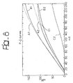
- figures 3 to 7 schematically show subsequent steps in the manufacturing process of a semiconductor laser structure according to the invention, and
- figure 8 is a diagram showing the behaviour of the solution of the invention in comparison with prior art arrangements.
- In figures 2 to 7 parts and components of a SIBH-DFB semiconductor laser structure which are identical or functionally equivalent to those already described in connection with figure 1 were designated with the same reference numerals appearing in figure 1.
- The exemplary, presently preferred embodiment of the invention shown in figure 2, provides for a thin (e.g. 0.2-0.3 micrometer)
p layer 10 being provided to separate the Fe-InP layers 2 from then layer 1, theMQW layers 3 and the P-InP layer 4 comprising the basic layer structure. - Preferably, layer 10 - which extends over the Fe-InP layers in direct contact therewith - is a p-InP layer doped with zinc (Zn) to 2.10+18/cm3.
- Provision of the p layer involves several advantages over the structures of the prior art.
- First of all, the leakage current at high temperatures is reduced to the point of being almost negligible while the p-
InP layer 10, being intrinsically thin, improves series resistance behaviour. - For a 1.3 micrometer wavelength SIBH laser, the mesa width will be in the range of 1.5 micrometers and the series resistance may be increased due to Zn-Fe interdiffusion between
layer 4 andlayer 2. The equivalent interdiffusion region is 0.2-0.3 micrometers. - However, with the insertion of the highly-doped P-InP layer 10 (0.2-0.3 micrometers) this Zn-Fe interdiffusion region is shifted out of the original mesa, whereby series resistance is unaffected by the interdiffusion effect. To minimise the Fe-Zn interdiffusion effects the Zn doping level in
layer 10 should be high enough, in the range of 2x1018 cm-3, while the Fe doping level inlayer 2 is optimised around 5x1016 cm-3, with a trade-off between high resistivity (high Fe doping level) and minimal Fe-diffusion effect (low Fe doping level). - The reduced thickness of
layer 10 also has little impact on the basic structure of figure 1 insofar as the Fe-InP layer 2 is concerned. Specifically, by resorting to current MOCVD growth techniques, a thicker Fe-InP layer can be easily grown to a thickness from between 1.0 and 2.0 micrometers, that is values currently required for 10 Gbit/s direct modulation, without being affected by the insertion of the thin P-InP layer 10. - Furthermore, in the arrangement of the invention direct contact between the Fe-InP layers and the MQW layers is avoided, thus avoiding Fe diffusion into the MQW layers.
- Finally, the structure of the invention is intrinsically simple to manufacture while also providing an extensive degree of freedom in controlling the mesa width and the Fe-InP thickness, reducing both series resistance and parasitic capacitance.
- The process of manufacturing a laser structure according to the invention will now be briefly discussed with reference to figures 3 to 7. Those skilled in the art will promptly appreciate that the various steps referred to are carried out by resorting to standard technologies and processes, thus rendering any detailed description of such technologies and processes unnecessary within the framework of the present description.
- Figure 3 essentially shows a n substrate over which the MQW active layers (jointly designated 3) and a thin (about 0.5 micrometers)
p cladding layer 4 are grown. - Again, those skilled in the art will promptly appreciate that relative proportions of the various layers involved were not strictly reproduced to scale in figures 3 to 7 in order to facilitate understanding of the steps described.
- After forming a SiO2 (or Si3N4) mask on top of the layers already provided, a typical mesa structure of about 2 micrometer width is formed by a first reactive ion etching (RIE) step (figure 4). This is followed by a slight wet chemical etch to form an "underetch" of typically less than 0.5 micrometer under mask 5 (figure 5).
- The highly doped thin p-
InP layer 10, the Fe-InPsemi-insulating layers 2 and the n-InP layers 6, having a thickness in the range of 0.5 micrometers and a doping level (Sn) of 1-2x10+18 cm-3 are subsequently grown by MOCVD (figure 6). - Finally, after removing
mask 5, p-InP and p-InGaAs cladding andcontact layers 7 and 8 are grown to complete the structure. This is subsequently subjected to deposition of p-metal, backside thinning and deposition of n-metal according to conventional finishing steps (not shown). - In the diagram of figure 8, power v. current (P-I) curves are shown which were derived for the laser structure of the invention (curves A1 and A2) referring to operation at nearly ambient temperature i.e. 27°C and 90°C, respectively.
- Corresponding curves are also shown in figure 8 for the structure of figure 1 (curves C1 and C2, again referring to operation at 27°C and 90°C, respectively) and for a similar arrangement using a p-n junction as the lateral blocking layer (curves B1 - 27°C and B2 - 90°C).
- Figure 8 shows that high temperature performance of the structure of the invention is comparable - and significantly better for high current values - with respect to low temperature performance of the conventional prior art structure of the figure 1.
- In comparison to both the sets of curves B1, B2 and C1, C2, the P-I curves of the invention (curves A1, A2) demonstrate improved performance both in terms absolute value and - more to the point - in terms of linearity.
- Even without wishing to be bound to any specific theory in that respect, the improved performance of the arrangement of the invention may perhaps be explained by considering that the arrangement of the invention gives rise to electron paths which enter into the mesa structure from below to give rise to a sort of funnel effect.
- Specifically, in the arrangement of the invention, the heavily p-doped
layer 10, grown laterally - and under - thesemi-insulating Fe regions 2 prevents electrons from leaking into the Fe-layer, effectively driving them into the MQW active layers also at high temperature. - Essentially, the arrangement of the invention solves the problem of resistivity loss in the Fe-InP layer at high temperature without giving rise to any limitation in growing the Fe-InP blocking layer, thus permitting e.g. a thin n-layer to be grown above the p-doped layer, without affecting performance.
- Of course, the basic principle of the invention remaining the same, the details and embodiments may vary with respect to the exemplary embodiment shown herein without departing from the scope of the invention as defined in the annexed claims.
Claims (13)
- A semiconductor laser structure including a region (1, 3, 4) comprising at least one active laser layer (3), said region being confined by at least one metal-doped lateral semi-insulating layer (2), characterised in that it includes a p layer (10) interposed as a blocking layer between said region (1, 3, 4) and said at least one lateral semi-insulating layer (2).
- The semiconductor laser of claim 1, characterised in that said p blocking layer (10) extends in direct contact with said at least one lateral semi-insulating layer (2).
- The semiconductor laser of either of claims 1 or 2, characterised in that said region is in the form of a mesa structure (1, 3, 4) confined by opposed lateral semi-insulating layers (2) and in that respective p layers are interposed as blocking layers (10) between said mesa structure (1, 3, 4) and said lateral semi-insulating layers (2).
- The semiconductor laser of any of claims 1 to 3, characterised in that said p blocking layer (10) also extends at the lower surface of said at least one lateral semi-insulating layer (2).
- The semiconductor laser of any of the preceding claims, characterised in that said p blocking layer (10) has a thickness of between 0.2 and 0.3 micrometers.
- The semiconductor laser of claim 1, characterised in that said p blocking layer (10) is a p-InP layer.
- The semiconductor laser of either of claims 1 or 6, characterised in that said p blocking layer (10) is doped with a density in the range of 2.1018/cm3.
- The semiconductor laser of any of claims 1, 6 or 7, characterised in that said p blocking layer (10) is doped with zinc.
- The semiconductor laser of any of the preceding claims, characterised in that said at least one lateral semi-insulating layer (2) is a Fe doped semi-insulating layer.
- The semiconductor laser of any of the preceding claims, characterised in that said at least one lateral semi-insulating layer (2) is doped with a Fe level of 5x1016 cm-3.
- The semiconductor laser of any of claims 1, 9 or 10, characterised in that said at least one lateral semi-insulating layer (2) has a thickness between 1.0 and 2.0 micrometers.
- A method of manufacturing the semiconductor laser according to any of claims 1 to 11, characterised in that it includes the steps of:providing said region (1, 3, 4) including said at least one active laser layer (3),growing said p blocking layer (10) over said region (1, 3, 4),growing said at least one lateral semi-insulating layer (2) over said p blocking layer (10), andgrowing at least one lateral n-InP blocking layer (6) over said at least one lateral semi-insulating layer (2).
- The method of claim 12, wherein said p blocking layer (10) is grown by metal organic chemical vapour deposition (MOCVD).
Priority Applications (2)
| Application Number | Priority Date | Filing Date | Title |
|---|---|---|---|
| EP01305504A EP1271722A1 (en) | 2001-06-25 | 2001-06-25 | Semiconductor laser structure and method of manufacturing same |
| US10/178,793 US6775309B2 (en) | 2001-06-25 | 2002-06-25 | Semiconductor laser structure and method of manufacturing same |
Applications Claiming Priority (1)
| Application Number | Priority Date | Filing Date | Title |
|---|---|---|---|
| EP01305504A EP1271722A1 (en) | 2001-06-25 | 2001-06-25 | Semiconductor laser structure and method of manufacturing same |
Publications (1)
| Publication Number | Publication Date |
|---|---|
| EP1271722A1 true EP1271722A1 (en) | 2003-01-02 |
Family
ID=8182055
Family Applications (1)
| Application Number | Title | Priority Date | Filing Date |
|---|---|---|---|
| EP01305504A Withdrawn EP1271722A1 (en) | 2001-06-25 | 2001-06-25 | Semiconductor laser structure and method of manufacturing same |
Country Status (2)
| Country | Link |
|---|---|
| US (1) | US6775309B2 (en) |
| EP (1) | EP1271722A1 (en) |
Families Citing this family (7)
| Publication number | Priority date | Publication date | Assignee | Title |
|---|---|---|---|---|
| US20050141800A1 (en) * | 2002-09-17 | 2005-06-30 | Mitsubishi Denki Kabushiki Kaisha | Waveguide semiconductor optical device and process of fabricating the device |
| US6778581B1 (en) * | 2002-09-24 | 2004-08-17 | Finisar Corporation | Tunable vertical cavity surface emitting laser |
| JP5803366B2 (en) * | 2011-07-14 | 2015-11-04 | 住友電気工業株式会社 | Method of manufacturing buried heterostructure semiconductor laser and buried heterostructure semiconductor laser |
| JP2015233093A (en) * | 2014-06-10 | 2015-12-24 | 住友電気工業株式会社 | Semiconductor device and manufacturing method thereof |
| JP2017188558A (en) * | 2016-04-05 | 2017-10-12 | 日本電信電話株式会社 | Semiconductor optical element |
| JP2018006590A (en) * | 2016-07-04 | 2018-01-11 | 日本電信電話株式会社 | Optical semiconductor element |
| JP7010546B2 (en) * | 2017-10-11 | 2022-01-26 | 住友電工デバイス・イノベーション株式会社 | Optical semiconductor devices and their manufacturing methods |
Citations (3)
| Publication number | Priority date | Publication date | Assignee | Title |
|---|---|---|---|---|
| JPH09214045A (en) * | 1996-01-30 | 1997-08-15 | Fujitsu Ltd | Semiconductor laser and manufacturing method thereof |
| US5822349A (en) * | 1995-03-15 | 1998-10-13 | Kabushiki Kaisha Toshiba | Semiconductor device and method of manufacturing the same |
| JP2000216500A (en) * | 1999-01-21 | 2000-08-04 | Hitachi Ltd | Semiconductor optical device, semiconductor optical device array, and optical communication system using the same |
Family Cites Families (9)
| Publication number | Priority date | Publication date | Assignee | Title |
|---|---|---|---|---|
| US4829347A (en) * | 1987-02-06 | 1989-05-09 | American Telephone And Telegraph Company, At&T Bell Laboratories | Process for making indium gallium arsenide devices |
| JPH05167191A (en) * | 1991-12-18 | 1993-07-02 | Furukawa Electric Co Ltd:The | Buried type semiconductor laser element |
| DE69404367T2 (en) * | 1993-03-25 | 1998-02-26 | Nippon Electric Co | Planar buried heterostructure laser diode with two channels and low leakage current |
| JPH07254732A (en) * | 1994-03-15 | 1995-10-03 | Toshiba Corp | Semiconductor light emitting device |
| JP3729210B2 (en) * | 1994-07-26 | 2005-12-21 | 富士通株式会社 | Manufacturing method of semiconductor device |
| US6198863B1 (en) * | 1995-10-06 | 2001-03-06 | British Telecommunications Public Limited Company | Optical filters |
| JP3941296B2 (en) * | 1999-09-20 | 2007-07-04 | 三菱電機株式会社 | Modulator, semiconductor laser device with modulator, and manufacturing method thereof |
| US6437372B1 (en) * | 2000-01-07 | 2002-08-20 | Agere Systems Guardian Corp. | Diffusion barrier spikes for III-V structures |
| US6556605B1 (en) * | 2000-02-29 | 2003-04-29 | Triquent Technology Holding, Co. | Method and device for preventing zinc/iron interaction in a semiconductor laser |
-
2001
- 2001-06-25 EP EP01305504A patent/EP1271722A1/en not_active Withdrawn
-
2002
- 2002-06-25 US US10/178,793 patent/US6775309B2/en not_active Expired - Lifetime
Patent Citations (3)
| Publication number | Priority date | Publication date | Assignee | Title |
|---|---|---|---|---|
| US5822349A (en) * | 1995-03-15 | 1998-10-13 | Kabushiki Kaisha Toshiba | Semiconductor device and method of manufacturing the same |
| JPH09214045A (en) * | 1996-01-30 | 1997-08-15 | Fujitsu Ltd | Semiconductor laser and manufacturing method thereof |
| JP2000216500A (en) * | 1999-01-21 | 2000-08-04 | Hitachi Ltd | Semiconductor optical device, semiconductor optical device array, and optical communication system using the same |
Non-Patent Citations (6)
| Title |
|---|
| ASADA S ET AL: "Analysis of leakage current in buried heterostructure lasers with semiinsulating blocking layers", IEEE JOURNAL OF QUANTUM ELECTRONICS, JUNE 1989, USA, vol. 25, no. 6, pages 1362 - 1368, XP001042078, ISSN: 0018-9197 * |
| HARLOW M J ET AL: "CHROMIUM-DOPED SEMI-INSULATING INP GROWN BY METALORGANIC VAPOUR PHASE EPITAXY", JOURNAL OF CRYSTAL GROWTH, NORTH-HOLLAND PUBLISHING CO. AMSTERDAM, NL, vol. 140, no. 1/2, 1 June 1994 (1994-06-01), pages 19 - 27, XP000469692, ISSN: 0022-0248 * |
| HARLOW M.J. ET AL.: "Journal of crystal growth", vol. 140, 1 June 1994, NORTH-HOLLAND PUBLISHING CO., article "Chromium-doped semi-insulating InP grown by metalorganic vapour phase epitaxy", pages: 19 - 27 |
| PATENT ABSTRACTS OF JAPAN vol. 1997, no. 12 25 December 1997 (1997-12-25) * |
| PATENT ABSTRACTS OF JAPAN vol. 2000, no. 11 3 January 2001 (2001-01-03) * |
| S. ASADA ET AL.: "Analysis of Leakage Current in Buried Heterostructure Lasers with Semiinsulating Blocking Layers", IEEE JOURNAL OF QUANTUM ELECTRONICS, vol. 25, no. 6, June 1989 (1989-06-01), pages 1362 - 1368 |
Also Published As
| Publication number | Publication date |
|---|---|
| US6775309B2 (en) | 2004-08-10 |
| US20030007529A1 (en) | 2003-01-09 |
Similar Documents
| Publication | Publication Date | Title |
|---|---|---|
| US6317444B1 (en) | Optical device including carbon-doped contact layers | |
| EP0259026B1 (en) | Double-heterostructure semiconductor laser with mesa stripe waveguide | |
| US6664605B1 (en) | Dopant diffusion blocking for optoelectronic devices using InAlAs and/or InGaAlAs | |
| US5717707A (en) | Index guided semiconductor laser diode with reduced shunt leakage currents | |
| US20090203161A1 (en) | Semiconductor laser diode with a ridge structure buried by a current blocking layer made of un-doped semiconductor grown at a low temperature and method for producing the same | |
| US6556605B1 (en) | Method and device for preventing zinc/iron interaction in a semiconductor laser | |
| KR100254005B1 (en) | Semiconductor device and manufacturing method thereof | |
| US6775309B2 (en) | Semiconductor laser structure and method of manufacturing same | |
| JP2005286192A (en) | Optical integrated device | |
| CN118783230B (en) | Photonic integrated chip structure and manufacturing method thereof | |
| EP0915542A2 (en) | Semiconductor laser having improved current blocking layers and method of forming the same | |
| US5887011A (en) | Semiconductor laser | |
| JP2780275B2 (en) | Embedded semiconductor laser | |
| US20250079803A1 (en) | Semiconductor device and method for manufacturing same | |
| US6653162B2 (en) | Fabrication method of optical device having current blocking layer of buried ridge structure | |
| KR100279734B1 (en) | Planar Embedded Semiconductor Laser Structure and Manufacturing Method Thereof | |
| JP3146501B2 (en) | Semiconductor laser and method of manufacturing the same | |
| JP2002026455A (en) | Semiconductor optical device and method of manufacturing the same | |
| JPH0851255A (en) | Semiconductor laser and manufacturing method thereof | |
| JP2001085795A (en) | Semiconductor device and semiconductor light emitting device | |
| JPH05190970A (en) | Semiconductor laser manufacturing method | |
| JP2555984B2 (en) | Semiconductor laser and manufacturing method thereof | |
| US20050189552A1 (en) | Semiconductor light-emitting device | |
| US20060243992A1 (en) | Semiconductor light-emitting device | |
| JPS6237557B2 (en) |
Legal Events
| Date | Code | Title | Description |
|---|---|---|---|
| PUAI | Public reference made under article 153(3) epc to a published international application that has entered the european phase |
Free format text: ORIGINAL CODE: 0009012 |
|
| AK | Designated contracting states |
Kind code of ref document: A1 Designated state(s): AT BE CH CY DE DK ES FI FR GB GR IE IT LI LU MC NL PT SE TR |
|
| AX | Request for extension of the european patent |
Free format text: AL;LT;LV;MK;RO;SI |
|
| 17P | Request for examination filed |
Effective date: 20030702 |
|
| AKX | Designation fees paid |
Designated state(s): DE FR GB |
|
| RAP1 | Party data changed (applicant data changed or rights of an application transferred) |
Owner name: AVAGO TECHNOLOGIES FIBER IP (SINGAPORE) PTE. LTD. |
|
| 17Q | First examination report despatched |
Effective date: 20081014 |
|
| STAA | Information on the status of an ep patent application or granted ep patent |
Free format text: STATUS: THE APPLICATION IS DEEMED TO BE WITHDRAWN |
|
| 18D | Application deemed to be withdrawn |
Effective date: 20120104 |