EP1271710A1 - Liaison de continuité électrique - Google Patents
Liaison de continuité électrique Download PDFInfo
- Publication number
- EP1271710A1 EP1271710A1 EP02100708A EP02100708A EP1271710A1 EP 1271710 A1 EP1271710 A1 EP 1271710A1 EP 02100708 A EP02100708 A EP 02100708A EP 02100708 A EP02100708 A EP 02100708A EP 1271710 A1 EP1271710 A1 EP 1271710A1
- Authority
- EP
- European Patent Office
- Prior art keywords
- contact
- ring
- connector
- housing
- connector according
- Prior art date
- Legal status (The legal status is an assumption and is not a legal conclusion. Google has not performed a legal analysis and makes no representation as to the accuracy of the status listed.)
- Granted
Links
- 239000012212 insulator Substances 0.000 claims description 7
- 239000007787 solid Substances 0.000 claims 1
- 239000004020 conductor Substances 0.000 description 7
- 230000000717 retained effect Effects 0.000 description 5
- 239000002184 metal Substances 0.000 description 4
- 230000000295 complement effect Effects 0.000 description 3
- 229920006335 epoxy glue Polymers 0.000 description 2
- 239000000758 substrate Substances 0.000 description 2
- 230000037431 insertion Effects 0.000 description 1
- 238000003780 insertion Methods 0.000 description 1
- 238000003754 machining Methods 0.000 description 1
- 238000004519 manufacturing process Methods 0.000 description 1
- 210000002105 tongue Anatomy 0.000 description 1
Images
Classifications
-
- H—ELECTRICITY
- H01—ELECTRIC ELEMENTS
- H01R—ELECTRICALLY-CONDUCTIVE CONNECTIONS; STRUCTURAL ASSOCIATIONS OF A PLURALITY OF MUTUALLY-INSULATED ELECTRICAL CONNECTING ELEMENTS; COUPLING DEVICES; CURRENT COLLECTORS
- H01R13/00—Details of coupling devices of the kinds covered by groups H01R12/70 or H01R24/00 - H01R33/00
- H01R13/648—Protective earth or shield arrangements on coupling devices, e.g. anti-static shielding
- H01R13/658—High frequency shielding arrangements, e.g. against EMI [Electro-Magnetic Interference] or EMP [Electro-Magnetic Pulse]
- H01R13/6581—Shield structure
- H01R13/6585—Shielding material individually surrounding or interposed between mutually spaced contacts
-
- H—ELECTRICITY
- H01—ELECTRIC ELEMENTS
- H01R—ELECTRICALLY-CONDUCTIVE CONNECTIONS; STRUCTURAL ASSOCIATIONS OF A PLURALITY OF MUTUALLY-INSULATED ELECTRICAL CONNECTING ELEMENTS; COUPLING DEVICES; CURRENT COLLECTORS
- H01R24/00—Two-part coupling devices, or either of their cooperating parts, characterised by their overall structure
- H01R24/38—Two-part coupling devices, or either of their cooperating parts, characterised by their overall structure having concentrically or coaxially arranged contacts
- H01R24/40—Two-part coupling devices, or either of their cooperating parts, characterised by their overall structure having concentrically or coaxially arranged contacts specially adapted for high frequency
-
- H—ELECTRICITY
- H01—ELECTRIC ELEMENTS
- H01R—ELECTRICALLY-CONDUCTIVE CONNECTIONS; STRUCTURAL ASSOCIATIONS OF A PLURALITY OF MUTUALLY-INSULATED ELECTRICAL CONNECTING ELEMENTS; COUPLING DEVICES; CURRENT COLLECTORS
- H01R9/00—Structural associations of a plurality of mutually-insulated electrical connecting elements, e.g. terminal strips or terminal blocks; Terminals or binding posts mounted upon a base or in a case; Bases therefor
- H01R9/03—Connectors arranged to contact a plurality of the conductors of a multiconductor cable, e.g. tapping connections
- H01R9/05—Connectors arranged to contact a plurality of the conductors of a multiconductor cable, e.g. tapping connections for coaxial cables
Definitions
- the present invention relates to an electrical continuity link. It finds more particularly its use in the field of connectors designed to receive coaxial cables for which a continuity of the mass must be ensured.
- she finds a application in connectors intended to be mounted on devices on board, for example at the rear of aircraft dashboards. Indeed, we provides, on board aircraft, electrical and electronic devices in front be permanently powered and properly connected to each other. But, such an aeronautical environment creates significant vibrations at the level of each of these devices. Micro-cuts cannot be tolerated in such an environment.
- the advantage of the invention is to propose a connector ensuring an efficient connection even in the presence of vibration.
- a connector comprising a metal contact extending through an insulating body of the connector.
- Contact receives on the one hand a cable and on the other hand has a connection end.
- the contact is arranged in a channel of the insulating body in which it is retained by means of an elastic lock.
- This elastic lock is for example constituted by elastic tongues deviating from the trunk of the contact to come into abutment against an interior recess in the channel. So it provides a mechanical and electrical connection of the contact with the housing.
- the elastic lock can for example be presented on a mounted insert around the contact.
- a connector comprising cables mounted in coaxial contacts, each contact being arranged in an insulating support retained inside a housing of the connector.
- An electrical connection between an outer perimeter of each of these contacts and the housing is produced by means of a plate conductive, arranged perpendicular to a connection axis of the contact.
- this plate has holes to let the contacts, and on the other hand has a dimension equivalent to that of the housing of the connector.
- the conductive plate preferably comes to connect with the contacts by means of elastic tabs arranged on a periphery inside the holes allowing these contacts to pass. For each hole, the legs elastic of the hole are oriented towards a center of this hole, so that when the contact is inserted into such a hole, the tabs are constraints on an outside periphery of the contact.
- Such a plate is obtained by machining. Indeed, we cut this plate so as to form a "lace" of legs (on each inner circumference of each hole). Then it is necessary to bend slightly in the same direction each of these legs to obtain elastic legs which can be constrained.
- the main problem with these connectors is that when they are used in devices subject to significant vibration regimes, the connections are themselves subject to micro-cuts. Now these micro-cuts cannot be tolerated insofar as the devices onboard must remain efficient no matter what.
- this risk of micro cuts is accentuated in the field of cable connectors coaxial since there are two connections to be made. Indeed, from except a connection must be ensured between the cable core and the contact, and on the other hand, a connection must be ensured between an outer braid of the cable and an outer periphery of the connector also ensuring continuity massive.
- the object of the invention is to remedy the problems cited by proposing a link ensuring continuity of mass.
- the solution provided by the invention comprises a connector comprising a housing and a substrate in this housing, such as a contact of this connector passes through the substrate to present on the one hand a cable end, and on the other hand an end of connection.
- the connector is more particularly intended to receive a coaxial cable.
- the contact has an inner circumference to come in contact with the core of the cable, an insulating intermediate layer for separate the inner perimeter of the contact from a conductive outer perimeter of that same contact.
- the conductive outer periphery of the contact is provided for be connected to a ground braid of the cable. So the contact provides double conduction: conduction of the main signal and conduction of mass signal.
- the invention provides that continuity of mass is ensured by the bias of an intermediate element disposed between the contact and a periphery inside of the case.
- This intermediate element is preferably connected with on the one hand a first ring and on the other hand a second ring.
- the invention particularly provides that the contact is surrounded by the first conductive ring so that this ring conductor is in electrical contact with the outer periphery of the contact conveying the mass contact.
- the first ring is itself brought into contact with the intermediate element.
- the intermediate element is no longer in contact through the second ring with the perimeter inside of the case.
- the continuity of the mass is thus ensured from the outer periphery of the contact up to the inner wall of the housing.
- the advantage presented by the invention is that it offers a means to ensure the continuity of the simple mass, easy to implement, by giving better results with regard to the appearance of micro-cuts electrical signals conveyed.
- one second ring mounted around an outer periphery of the element intermediate is constrained between the inside periphery of the case and the element intermediate.
- contact is guaranteed, and mass continuity too.
- the production of these rings is easy: they are of simple structure. And they can be easily machined.
- the invention therefore relates to a connector comprising a housing, a coaxial contact can be connected to a coaxial cable, an insulator for retain this contact in the housing, a means to ensure a connection between a ground braid of the cable and the housing, characterized in that the medium includes a first ring mounted around the contact, an insert conductor crossed by the contact surrounded by the ring, and a second ring surrounding the insert and pressed against an interior wall of the housing.
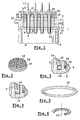
- FIG. 1 shows a connector 1 according to the invention.
- Connector 1 has a housing 2 in which is disposed a contact 3.
- the contact 3 is designed to preferably receive a coaxial cable (not shown).
- the connector 1 has a first side 4 of wiring and a second connection side 5.
- the coaxial cable is therefore introduced into the connector 1 from wiring face 4, so as to be connected with contact 3.
- a coaxial cable generally has an inner core conveying an electrical signal, this core being surrounded by a sheath insulating, and a metal braid on an outer periphery of the sheath insulating. The metal braid is used to convey a ground signal.
- the contact 3 has a socket 6 to receive the cable.
- This socket 6 is provided so that has a 7 conductor inner circumference which can be connected with the cable core.
- Contact 3 includes an insulating intermediate layer 8 surrounding the inner periphery 7.
- the contact 3 has a circumference outer 9 conductor to come into contact with the ground braid of the cable.
- the intermediate layer 8 makes it possible to isolate the inner periphery 7 of the outer edge 9. Thus the main electrical signal can be separated from the mass signal.
- This structure of contact 3 therefore ensures the ground continuity at the connection of a ground braid of a coaxial cable on a coaxial contact.
- the contact 3 is preferably mounted in an insulating support 10 of so as to be retained inside a cavity 11 of the housing 2.
- This insulator 10 is retained on the side of the wiring face 4 by an insulating plate 12 cooperating with a recess 13 of an inner periphery 14 of the cavity 11.
- the insulator 10 and the insulating plate 12 have channels for let the contacts pass through 3.
- the contacts 3 are retained in these channels, at the wiring face 4 by cooperation between the periphery outer 9 and an inner periphery of the channels formed respectively in the insulator 10 and the insulating plate 12.
- the contact 3 is arranged in this insulator 10 and respectively in this plate 12 so that a certain length of contact 3 protrudes from a rear surface 15 of the plate insulating 12, so as to be stretched in the direction of the wiring face 4.
- the connector 1 includes a conductive insert 16.
- This insert 16 is mounted in the cavity 11 by being inserted from the front connection face 5.
- This insert 16 has at least one channel for passing contact 3 and thus authorize the passing of one end 17 of contact 3 on the side of the connection front face 5.
- the insert 16 is an intermediate element conductor to ensure earth continuity.
- the insert 16 includes a outer collar 18.
- This outer collar 18 has a periphery exterior of a geometry complementary to a geometry of the wall interior 14. In a central part, interior to this collar 18, the insert 16 has a greater thickness. In this greater thickness are formed of channels 19 to allow contacts such as 3 to pass.
- Figure 2 shows an embodiment of an insert 16 according to the invention.
- the insert 16 comprises preferably several channels 19 to allow passage multiple contacts such as 3.
- first ring 20 around contact 3.
- This ring 20 is arranged so that it sinks inside the channel 19.
- the first ring 20 is forcibly mounted around the contact 3 and in the channel 19, so as to be forced both against the outer periphery 9 and against an inner wall 21 of this channel 19.
- These rings are preferably made of metal.
- a second ring 22 is provided.
- This second ring 22 is preferably mounted above the flange 18, and preferably inserted in force between an outer periphery 23 of the conductive insert 16 and the inner wall 14 of the housing 2.
- the continuity mass is ensured between the outer periphery 9 of the contact 3 and the wall inner 14 of the housing 2 through the first ring 20, the insert conductor 16 and the second ring 22.
- the connector 1 preferably comprises an insulator 24 at the level of the connection front face 5. Indeed, once the conductive insert 16, the first ring 20 and the second ring 22 in place to ensure the mass continuity, we then fill the space still free on the side of the face before connection 5 with epoxy glue.
- This layer of epoxy glue 24 is arranged so that only the end 17 of contact 3 protrudes the connection front face 5. This end 17 conveys the electrical signal main, and is a continuation of the inner periphery 7. Furthermore, the outer periphery conductor 9 ends inside the insert 16. And even the insulating intermediate layer ends at the layer insulating 24.
- Figure 3 shows a first embodiment of the connection allowing mass continuity between the outer periphery 9 and the wall inner 14 of the housing 2, wherein the first ring 20 has according to a transverse section plane, a circular section.
- the two rings 20 and 22 have a same circular section.
- the first ring 20 and or the second ring 22 have, according to a cutting plane longitudinal, a section in the shape of a truncated circle, or semicircle, or half oval.
- the semicircle can be hollowed out. Alternatively, this semicircle may be full.
- FIG. 5 presents a top view of an embodiment of the ring 22, this ring being closed and truncated according to a cutting plane transverse, thus giving it the shape of a truncated torus, possibly semicircle, and presenting a full interior.
- the first ring 20 and / or the second ring 22 can be open rings.
- the open ring is also a truncated ring according to a plane perpendicular to a connection axis 25 of the connector 1. And in the example shown in Figure 6, this open, truncated ring also has a partially hollowed out interior.
- a truncation surface 26 is preferably oriented towards the connection front face 5 for facilitate the insertion of this ring into the insert 16, either inside a channel 19, or around the collar 18.
Landscapes
- Coupling Device And Connection With Printed Circuit (AREA)
- Details Of Connecting Devices For Male And Female Coupling (AREA)
- Multi-Conductor Connections (AREA)
- Conductive Materials (AREA)
- Seal Device For Vehicle (AREA)
- Vehicle Body Suspensions (AREA)
- Contacts (AREA)
Abstract
Description
- Figure 1 : Une vue en coupe longitudinale d'un connecteur selon l'invention ;
- Figure 2 : Une vue de dessus d'un élément intermédiaire d'un connecteur selon l'invention ;
- Figure 3 : Une vue en coupe longitudinale d'une portion du connecteur selon l'invention ;
- Figure 4 : Une vue en coupe longitudinale d'un deuxième mode de réalisation de cette portion du connecteur selon l'invention ;
- Figure 5 : Une vue de dessus d'un anneau d'un connecteur selon l'invention ;
- Figure 6 : Une vue de dessus d'un deuxième mode de réalisation d'un anneau d'un connecteur selon l'invention.
Claims (9)
- Connecteur (1) comportant un boítier (2), un contact (3) coaxial pouvant être connecté à un câble coaxial, un isolant (10, 12) pour retenir ce contact dans le boítier, un moyen pour assurer une connexion entre une tresse de masse du câble et le boítier, caractérisé en ce que le moyen comporte un premier anneau (20) monté autour du contact, un insert conducteur (17) traversé par le contact entouré de l'anneau, et un deuxième anneau (22) entourant l'insert et appuyé contre une paroi intérieure (14) du boítier.
- Connecteur selon la revendication 1 caractérisé en ce que le contact coaxial comporte une pourtour intérieur (7) conducteur pour venir au contact d'une âme conductrice du câble, une couche intermédiaire isolante (8), et un pourtour extérieur (9) pour venir au contact de la tresse de masse du câble.
- Connecteur selon l'une des revendications 1 à 2 caractérisé en ce que le premier anneau est inséré en force entre le contact et un canal (19) de l'insert laissant passer le contact.
- Connecteur selon l'une des revendications 1 à 3 caractérisé en ce que le deuxième anneau est inséré en force entre l'insert et la paroi intérieure du boítier.
- Connecteur selon l'une des revendications 1 à 4 caractérisé en ce qu'au moins un anneau comporte une section pleine, circulaire ou ovale, selon un plan de coupe longitudinal.
- Connecteur selon l'une des revendications 1 à 5 caractérisé en ce qu'au moins un anneau comporte une section évidée en son centre selon un plan de coupe longitudinal.
- Connecteur selon l'une des revendications 1 à 6 caractérisé en ce qu'au moins un anneau est tronqué perpendiculairement à un axe de connexion (25) du connecteur.
- Connecteur selon l'une des revendications 1 à 7 caractérisé en ce qu'au moins un anneau est ouvert.
- Connecteur selon l'une des revendications 1 à 8 caractérisé en ce que les anneaux sont métalliques.
Applications Claiming Priority (2)
| Application Number | Priority Date | Filing Date | Title |
|---|---|---|---|
| FR0108217 | 2001-06-21 | ||
| FR0108217A FR2826514B1 (fr) | 2001-06-21 | 2001-06-21 | Liaison de continuite electrique |
Publications (2)
| Publication Number | Publication Date |
|---|---|
| EP1271710A1 true EP1271710A1 (fr) | 2003-01-02 |
| EP1271710B1 EP1271710B1 (fr) | 2003-11-26 |
Family
ID=8864629
Family Applications (1)
| Application Number | Title | Priority Date | Filing Date |
|---|---|---|---|
| EP02100708A Expired - Lifetime EP1271710B1 (fr) | 2001-06-21 | 2002-06-13 | Liaison de continuité électrique |
Country Status (4)
| Country | Link |
|---|---|
| EP (1) | EP1271710B1 (fr) |
| AT (1) | ATE255289T1 (fr) |
| DE (1) | DE60200100T2 (fr) |
| FR (1) | FR2826514B1 (fr) |
Citations (4)
| Publication number | Priority date | Publication date | Assignee | Title |
|---|---|---|---|---|
| US3569915A (en) * | 1968-09-16 | 1971-03-09 | Itt | Grounding foil |
| US3825874A (en) * | 1973-07-05 | 1974-07-23 | Itt | Electrical connector |
| US4382653A (en) * | 1980-12-04 | 1983-05-10 | Avco Corporation | Connector |
| US4598969A (en) * | 1984-12-12 | 1986-07-08 | Automation Industries, Inc. | Termination means |
-
2001
- 2001-06-21 FR FR0108217A patent/FR2826514B1/fr not_active Expired - Lifetime
-
2002
- 2002-06-13 EP EP02100708A patent/EP1271710B1/fr not_active Expired - Lifetime
- 2002-06-13 DE DE60200100T patent/DE60200100T2/de not_active Expired - Fee Related
- 2002-06-13 AT AT02100708T patent/ATE255289T1/de not_active IP Right Cessation
Patent Citations (4)
| Publication number | Priority date | Publication date | Assignee | Title |
|---|---|---|---|---|
| US3569915A (en) * | 1968-09-16 | 1971-03-09 | Itt | Grounding foil |
| US3825874A (en) * | 1973-07-05 | 1974-07-23 | Itt | Electrical connector |
| US4382653A (en) * | 1980-12-04 | 1983-05-10 | Avco Corporation | Connector |
| US4598969A (en) * | 1984-12-12 | 1986-07-08 | Automation Industries, Inc. | Termination means |
Also Published As
| Publication number | Publication date |
|---|---|
| DE60200100T2 (de) | 2004-08-19 |
| DE60200100D1 (de) | 2004-01-08 |
| EP1271710B1 (fr) | 2003-11-26 |
| FR2826514B1 (fr) | 2003-10-17 |
| FR2826514A1 (fr) | 2002-12-27 |
| ATE255289T1 (de) | 2003-12-15 |
Similar Documents
| Publication | Publication Date | Title |
|---|---|---|
| EP0692845B1 (fr) | Elément coudé de connecteur coaxial apte à être fixé à une carte imprimée | |
| EP2545616B1 (fr) | Dispositif de connexion electrique etanche a travers une paroi et procede de realisation correspondant | |
| EP2912725B1 (fr) | Contact électrique et circuit électronique | |
| EP0271413B1 (fr) | Connecteur par déplacement d'isolant pour câble monoconducteur | |
| EP0663706A1 (fr) | Connecteur coaxial microminiature à verrouillage par encliquetage | |
| CA2377781C (fr) | Tete de connexion pour casque d'ecoute stereophonique | |
| FR2814598A1 (fr) | Connecteur muni de contacts montes dans un isolant adapte | |
| FR2935072A1 (fr) | Element de connecteur multicontacts | |
| FR2850488A1 (fr) | Module photovoltaique comportant des bornes de connexion avec l'exterieur | |
| EP1540775B1 (fr) | Systeme d'etancheite pour connecteur electrique multi-broche | |
| FR2914788A1 (fr) | Ensemble porte-contacts electriques | |
| FR2937801A1 (fr) | Ensemble de connexion a verrouillage rapide et procede d'accouplement et de desaccouplement de l'ensemble | |
| EP1271710B1 (fr) | Liaison de continuité électrique | |
| EP3477789B1 (fr) | Adaptateur pour connecteur blindé, connecteur blindé et procédé de montage d'un connecteur blindé | |
| FR2989524A1 (fr) | Systeme de connexion monovoie rapide | |
| FR2783099A1 (fr) | Ensemble de connexion hermetique | |
| CA2434592A1 (fr) | Dispositif de liaison entre un cable et un element de contact | |
| EP2690734B1 (fr) | Joint d'étanchéité pour le passage de câbles | |
| FR2901644A1 (fr) | Procede de realisation d'une traversee filaire hermetique de cloison, et traversee obtenue | |
| EP3190668A1 (fr) | Connecteur résistant aux décharges partielles | |
| EP1422790A1 (fr) | Connecteur coaxial, notamment connecteur normalisé 7/16 | |
| EP1657749A2 (fr) | Boitier microelectroniques multiplans avec blindage interne | |
| EP2272135B1 (fr) | Dispositif pour prévenir l'établissement d'un arc électrique entre deux éléments conducteurs | |
| FR2740920A1 (fr) | Dispositif de raccord arriere pour connecteur electrique | |
| EP0340066B1 (fr) | Connecteur électrique |
Legal Events
| Date | Code | Title | Description |
|---|---|---|---|
| PUAI | Public reference made under article 153(3) epc to a published international application that has entered the european phase |
Free format text: ORIGINAL CODE: 0009012 |
|
| AK | Designated contracting states |
Kind code of ref document: A1 Designated state(s): AT BE CH CY DE DK ES FI FR GB GR IE IT LI LU MC NL PT SE TR |
|
| AX | Request for extension of the european patent |
Free format text: AL;LT;LV;MK;RO;SI |
|
| GRAH | Despatch of communication of intention to grant a patent |
Free format text: ORIGINAL CODE: EPIDOS IGRA |
|
| 17P | Request for examination filed |
Effective date: 20030417 |
|
| GRAS | Grant fee paid |
Free format text: ORIGINAL CODE: EPIDOSNIGR3 |
|
| AKX | Designation fees paid |
Designated state(s): AT BE CH CY DE DK ES FI FR GB GR IE IT LI LU MC NL PT SE TR |
|
| GRAA | (expected) grant |
Free format text: ORIGINAL CODE: 0009210 |
|
| AK | Designated contracting states |
Kind code of ref document: B1 Designated state(s): AT BE CH CY DE DK ES FI FR GB GR IE IT LI LU MC NL PT SE TR |
|
| PG25 | Lapsed in a contracting state [announced via postgrant information from national office to epo] |
Ref country code: TR Free format text: LAPSE BECAUSE OF FAILURE TO SUBMIT A TRANSLATION OF THE DESCRIPTION OR TO PAY THE FEE WITHIN THE PRESCRIBED TIME-LIMIT Effective date: 20031126 Ref country code: NL Free format text: LAPSE BECAUSE OF FAILURE TO SUBMIT A TRANSLATION OF THE DESCRIPTION OR TO PAY THE FEE WITHIN THE PRESCRIBED TIME-LIMIT Effective date: 20031126 Ref country code: IT Free format text: LAPSE BECAUSE OF FAILURE TO SUBMIT A TRANSLATION OF THE DESCRIPTION OR TO PAY THE FEE WITHIN THE PRESCRIBED TIME-LIMIT;WARNING: LAPSES OF ITALIAN PATENTS WITH EFFECTIVE DATE BEFORE 2007 MAY HAVE OCCURRED AT ANY TIME BEFORE 2007. THE CORRECT EFFECTIVE DATE MAY BE DIFFERENT FROM THE ONE RECORDED. Effective date: 20031126 Ref country code: IE Free format text: LAPSE BECAUSE OF FAILURE TO SUBMIT A TRANSLATION OF THE DESCRIPTION OR TO PAY THE FEE WITHIN THE PRESCRIBED TIME-LIMIT Effective date: 20031126 Ref country code: FI Free format text: LAPSE BECAUSE OF FAILURE TO SUBMIT A TRANSLATION OF THE DESCRIPTION OR TO PAY THE FEE WITHIN THE PRESCRIBED TIME-LIMIT Effective date: 20031126 Ref country code: ES Free format text: LAPSE BECAUSE OF FAILURE TO SUBMIT A TRANSLATION OF THE DESCRIPTION OR TO PAY THE FEE WITHIN THE PRESCRIBED TIME-LIMIT Effective date: 20031126 Ref country code: CY Free format text: LAPSE BECAUSE OF FAILURE TO SUBMIT A TRANSLATION OF THE DESCRIPTION OR TO PAY THE FEE WITHIN THE PRESCRIBED TIME-LIMIT Effective date: 20031126 Ref country code: AT Free format text: LAPSE BECAUSE OF FAILURE TO SUBMIT A TRANSLATION OF THE DESCRIPTION OR TO PAY THE FEE WITHIN THE PRESCRIBED TIME-LIMIT Effective date: 20031126 |
|
| REG | Reference to a national code |
Ref country code: GB Ref legal event code: FG4D Free format text: NOT ENGLISH |
|
| REG | Reference to a national code |
Ref country code: CH Ref legal event code: EP |
|
| REF | Corresponds to: |
Ref document number: 60200100 Country of ref document: DE Date of ref document: 20040108 Kind code of ref document: P |
|
| REG | Reference to a national code |
Ref country code: IE Ref legal event code: FG4D Free format text: FRENCH |
|
| GBT | Gb: translation of ep patent filed (gb section 77(6)(a)/1977) |
Effective date: 20040121 |
|
| PG25 | Lapsed in a contracting state [announced via postgrant information from national office to epo] |
Ref country code: SE Free format text: LAPSE BECAUSE OF FAILURE TO SUBMIT A TRANSLATION OF THE DESCRIPTION OR TO PAY THE FEE WITHIN THE PRESCRIBED TIME-LIMIT Effective date: 20040226 Ref country code: GR Free format text: LAPSE BECAUSE OF FAILURE TO SUBMIT A TRANSLATION OF THE DESCRIPTION OR TO PAY THE FEE WITHIN THE PRESCRIBED TIME-LIMIT Effective date: 20040226 Ref country code: DK Free format text: LAPSE BECAUSE OF FAILURE TO SUBMIT A TRANSLATION OF THE DESCRIPTION OR TO PAY THE FEE WITHIN THE PRESCRIBED TIME-LIMIT Effective date: 20040226 |
|
| NLV1 | Nl: lapsed or annulled due to failure to fulfill the requirements of art. 29p and 29m of the patents act | ||
| PGFP | Annual fee paid to national office [announced via postgrant information from national office to epo] |
Ref country code: FR Payment date: 20040503 Year of fee payment: 3 |
|
| PGFP | Annual fee paid to national office [announced via postgrant information from national office to epo] |
Ref country code: DE Payment date: 20040526 Year of fee payment: 3 |
|
| PG25 | Lapsed in a contracting state [announced via postgrant information from national office to epo] |
Ref country code: LU Free format text: LAPSE BECAUSE OF NON-PAYMENT OF DUE FEES Effective date: 20040613 |
|
| PG25 | Lapsed in a contracting state [announced via postgrant information from national office to epo] |
Ref country code: MC Free format text: LAPSE BECAUSE OF NON-PAYMENT OF DUE FEES Effective date: 20040630 Ref country code: BE Free format text: LAPSE BECAUSE OF NON-PAYMENT OF DUE FEES Effective date: 20040630 |
|
| REG | Reference to a national code |
Ref country code: IE Ref legal event code: FD4D |
|
| PLBE | No opposition filed within time limit |
Free format text: ORIGINAL CODE: 0009261 |
|
| STAA | Information on the status of an ep patent application or granted ep patent |
Free format text: STATUS: NO OPPOSITION FILED WITHIN TIME LIMIT |
|
| 26N | No opposition filed |
Effective date: 20040827 |
|
| BERE | Be: lapsed |
Owner name: *FCI Effective date: 20040630 |
|
| PG25 | Lapsed in a contracting state [announced via postgrant information from national office to epo] |
Ref country code: DE Free format text: LAPSE BECAUSE OF NON-PAYMENT OF DUE FEES Effective date: 20060103 |
|
| PG25 | Lapsed in a contracting state [announced via postgrant information from national office to epo] |
Ref country code: FR Free format text: LAPSE BECAUSE OF NON-PAYMENT OF DUE FEES Effective date: 20060228 |
|
| REG | Reference to a national code |
Ref country code: FR Ref legal event code: ST Effective date: 20060228 |
|
| PGFP | Annual fee paid to national office [announced via postgrant information from national office to epo] |
Ref country code: GB Payment date: 20060530 Year of fee payment: 5 |
|
| PG25 | Lapsed in a contracting state [announced via postgrant information from national office to epo] |
Ref country code: LI Free format text: LAPSE BECAUSE OF NON-PAYMENT OF DUE FEES Effective date: 20060630 Ref country code: CH Free format text: LAPSE BECAUSE OF NON-PAYMENT OF DUE FEES Effective date: 20060630 |
|
| REG | Reference to a national code |
Ref country code: CH Ref legal event code: PL |
|
| PG25 | Lapsed in a contracting state [announced via postgrant information from national office to epo] |
Ref country code: PT Free format text: LAPSE BECAUSE OF NON-PAYMENT OF DUE FEES Effective date: 20040426 |
|
| GBPC | Gb: european patent ceased through non-payment of renewal fee |
Effective date: 20070613 |
|
| PG25 | Lapsed in a contracting state [announced via postgrant information from national office to epo] |
Ref country code: GB Free format text: LAPSE BECAUSE OF NON-PAYMENT OF DUE FEES Effective date: 20070613 |