EP1271672A1 - Secondary cell and method for bonding lead thereof, and battery power supply - Google Patents
Secondary cell and method for bonding lead thereof, and battery power supply Download PDFInfo
- Publication number
- EP1271672A1 EP1271672A1 EP01912369A EP01912369A EP1271672A1 EP 1271672 A1 EP1271672 A1 EP 1271672A1 EP 01912369 A EP01912369 A EP 01912369A EP 01912369 A EP01912369 A EP 01912369A EP 1271672 A1 EP1271672 A1 EP 1271672A1
- Authority
- EP
- European Patent Office
- Prior art keywords
- battery
- circuit board
- rechargeable
- power source
- rechargeable batteries
- Prior art date
- Legal status (The legal status is an assumption and is not a legal conclusion. Google has not performed a legal analysis and makes no representation as to the accuracy of the status listed.)
- Withdrawn
Links
Images















Classifications
-
- H—ELECTRICITY
- H01—ELECTRIC ELEMENTS
- H01M—PROCESSES OR MEANS, e.g. BATTERIES, FOR THE DIRECT CONVERSION OF CHEMICAL ENERGY INTO ELECTRICAL ENERGY
- H01M10/00—Secondary cells; Manufacture thereof
- H01M10/42—Methods or arrangements for servicing or maintenance of secondary cells or secondary half-cells
- H01M10/425—Structural combination with electronic components, e.g. electronic circuits integrated to the outside of the casing
-
- H—ELECTRICITY
- H01—ELECTRIC ELEMENTS
- H01M—PROCESSES OR MEANS, e.g. BATTERIES, FOR THE DIRECT CONVERSION OF CHEMICAL ENERGY INTO ELECTRICAL ENERGY
- H01M50/00—Constructional details or processes of manufacture of the non-active parts of electrochemical cells other than fuel cells, e.g. hybrid cells
- H01M50/20—Mountings; Secondary casings or frames; Racks, modules or packs; Suspension devices; Shock absorbers; Transport or carrying devices; Holders
- H01M50/204—Racks, modules or packs for multiple batteries or multiple cells
- H01M50/207—Racks, modules or packs for multiple batteries or multiple cells characterised by their shape
- H01M50/211—Racks, modules or packs for multiple batteries or multiple cells characterised by their shape adapted for pouch cells
-
- H—ELECTRICITY
- H01—ELECTRIC ELEMENTS
- H01M—PROCESSES OR MEANS, e.g. BATTERIES, FOR THE DIRECT CONVERSION OF CHEMICAL ENERGY INTO ELECTRICAL ENERGY
- H01M50/00—Constructional details or processes of manufacture of the non-active parts of electrochemical cells other than fuel cells, e.g. hybrid cells
- H01M50/50—Current conducting connections for cells or batteries
- H01M50/502—Interconnectors for connecting terminals of adjacent batteries; Interconnectors for connecting cells outside a battery casing
- H01M50/503—Interconnectors for connecting terminals of adjacent batteries; Interconnectors for connecting cells outside a battery casing characterised by the shape of the interconnectors
-
- H—ELECTRICITY
- H01—ELECTRIC ELEMENTS
- H01M—PROCESSES OR MEANS, e.g. BATTERIES, FOR THE DIRECT CONVERSION OF CHEMICAL ENERGY INTO ELECTRICAL ENERGY
- H01M50/00—Constructional details or processes of manufacture of the non-active parts of electrochemical cells other than fuel cells, e.g. hybrid cells
- H01M50/50—Current conducting connections for cells or batteries
- H01M50/502—Interconnectors for connecting terminals of adjacent batteries; Interconnectors for connecting cells outside a battery casing
- H01M50/505—Interconnectors for connecting terminals of adjacent batteries; Interconnectors for connecting cells outside a battery casing comprising a single busbar
-
- H—ELECTRICITY
- H01—ELECTRIC ELEMENTS
- H01M—PROCESSES OR MEANS, e.g. BATTERIES, FOR THE DIRECT CONVERSION OF CHEMICAL ENERGY INTO ELECTRICAL ENERGY
- H01M50/00—Constructional details or processes of manufacture of the non-active parts of electrochemical cells other than fuel cells, e.g. hybrid cells
- H01M50/50—Current conducting connections for cells or batteries
- H01M50/502—Interconnectors for connecting terminals of adjacent batteries; Interconnectors for connecting cells outside a battery casing
- H01M50/509—Interconnectors for connecting terminals of adjacent batteries; Interconnectors for connecting cells outside a battery casing characterised by the type of connection, e.g. mixed connections
-
- H—ELECTRICITY
- H01—ELECTRIC ELEMENTS
- H01M—PROCESSES OR MEANS, e.g. BATTERIES, FOR THE DIRECT CONVERSION OF CHEMICAL ENERGY INTO ELECTRICAL ENERGY
- H01M50/00—Constructional details or processes of manufacture of the non-active parts of electrochemical cells other than fuel cells, e.g. hybrid cells
- H01M50/50—Current conducting connections for cells or batteries
- H01M50/502—Interconnectors for connecting terminals of adjacent batteries; Interconnectors for connecting cells outside a battery casing
- H01M50/509—Interconnectors for connecting terminals of adjacent batteries; Interconnectors for connecting cells outside a battery casing characterised by the type of connection, e.g. mixed connections
- H01M50/51—Connection only in series
-
- H—ELECTRICITY
- H01—ELECTRIC ELEMENTS
- H01M—PROCESSES OR MEANS, e.g. BATTERIES, FOR THE DIRECT CONVERSION OF CHEMICAL ENERGY INTO ELECTRICAL ENERGY
- H01M50/00—Constructional details or processes of manufacture of the non-active parts of electrochemical cells other than fuel cells, e.g. hybrid cells
- H01M50/50—Current conducting connections for cells or batteries
- H01M50/502—Interconnectors for connecting terminals of adjacent batteries; Interconnectors for connecting cells outside a battery casing
- H01M50/509—Interconnectors for connecting terminals of adjacent batteries; Interconnectors for connecting cells outside a battery casing characterised by the type of connection, e.g. mixed connections
- H01M50/512—Connection only in parallel
-
- H—ELECTRICITY
- H01—ELECTRIC ELEMENTS
- H01M—PROCESSES OR MEANS, e.g. BATTERIES, FOR THE DIRECT CONVERSION OF CHEMICAL ENERGY INTO ELECTRICAL ENERGY
- H01M50/00—Constructional details or processes of manufacture of the non-active parts of electrochemical cells other than fuel cells, e.g. hybrid cells
- H01M50/50—Current conducting connections for cells or batteries
- H01M50/502—Interconnectors for connecting terminals of adjacent batteries; Interconnectors for connecting cells outside a battery casing
- H01M50/514—Methods for interconnecting adjacent batteries or cells
- H01M50/516—Methods for interconnecting adjacent batteries or cells by welding, soldering or brazing
-
- H—ELECTRICITY
- H01—ELECTRIC ELEMENTS
- H01M—PROCESSES OR MEANS, e.g. BATTERIES, FOR THE DIRECT CONVERSION OF CHEMICAL ENERGY INTO ELECTRICAL ENERGY
- H01M50/00—Constructional details or processes of manufacture of the non-active parts of electrochemical cells other than fuel cells, e.g. hybrid cells
- H01M50/50—Current conducting connections for cells or batteries
- H01M50/502—Interconnectors for connecting terminals of adjacent batteries; Interconnectors for connecting cells outside a battery casing
- H01M50/521—Interconnectors for connecting terminals of adjacent batteries; Interconnectors for connecting cells outside a battery casing characterised by the material
- H01M50/522—Inorganic material
-
- H—ELECTRICITY
- H01—ELECTRIC ELEMENTS
- H01M—PROCESSES OR MEANS, e.g. BATTERIES, FOR THE DIRECT CONVERSION OF CHEMICAL ENERGY INTO ELECTRICAL ENERGY
- H01M50/00—Constructional details or processes of manufacture of the non-active parts of electrochemical cells other than fuel cells, e.g. hybrid cells
- H01M50/50—Current conducting connections for cells or batteries
- H01M50/543—Terminals
- H01M50/547—Terminals characterised by the disposition of the terminals on the cells
- H01M50/55—Terminals characterised by the disposition of the terminals on the cells on the same side of the cell
-
- H—ELECTRICITY
- H01—ELECTRIC ELEMENTS
- H01M—PROCESSES OR MEANS, e.g. BATTERIES, FOR THE DIRECT CONVERSION OF CHEMICAL ENERGY INTO ELECTRICAL ENERGY
- H01M50/00—Constructional details or processes of manufacture of the non-active parts of electrochemical cells other than fuel cells, e.g. hybrid cells
- H01M50/50—Current conducting connections for cells or batteries
- H01M50/543—Terminals
- H01M50/552—Terminals characterised by their shape
- H01M50/553—Terminals adapted for prismatic, pouch or rectangular cells
-
- H—ELECTRICITY
- H01—ELECTRIC ELEMENTS
- H01M—PROCESSES OR MEANS, e.g. BATTERIES, FOR THE DIRECT CONVERSION OF CHEMICAL ENERGY INTO ELECTRICAL ENERGY
- H01M50/00—Constructional details or processes of manufacture of the non-active parts of electrochemical cells other than fuel cells, e.g. hybrid cells
- H01M50/50—Current conducting connections for cells or batteries
- H01M50/543—Terminals
- H01M50/562—Terminals characterised by the material
-
- H—ELECTRICITY
- H01—ELECTRIC ELEMENTS
- H01M—PROCESSES OR MEANS, e.g. BATTERIES, FOR THE DIRECT CONVERSION OF CHEMICAL ENERGY INTO ELECTRICAL ENERGY
- H01M10/00—Secondary cells; Manufacture thereof
- H01M10/05—Accumulators with non-aqueous electrolyte
- H01M10/052—Li-accumulators
-
- H—ELECTRICITY
- H01—ELECTRIC ELEMENTS
- H01M—PROCESSES OR MEANS, e.g. BATTERIES, FOR THE DIRECT CONVERSION OF CHEMICAL ENERGY INTO ELECTRICAL ENERGY
- H01M10/00—Secondary cells; Manufacture thereof
- H01M10/42—Methods or arrangements for servicing or maintenance of secondary cells or secondary half-cells
- H01M10/46—Accumulators structurally combined with charging apparatus
-
- H—ELECTRICITY
- H01—ELECTRIC ELEMENTS
- H01M—PROCESSES OR MEANS, e.g. BATTERIES, FOR THE DIRECT CONVERSION OF CHEMICAL ENERGY INTO ELECTRICAL ENERGY
- H01M2200/00—Safety devices for primary or secondary batteries
-
- H—ELECTRICITY
- H01—ELECTRIC ELEMENTS
- H01M—PROCESSES OR MEANS, e.g. BATTERIES, FOR THE DIRECT CONVERSION OF CHEMICAL ENERGY INTO ELECTRICAL ENERGY
- H01M2200/00—Safety devices for primary or secondary batteries
- H01M2200/10—Temperature sensitive devices
- H01M2200/106—PTC
-
- Y—GENERAL TAGGING OF NEW TECHNOLOGICAL DEVELOPMENTS; GENERAL TAGGING OF CROSS-SECTIONAL TECHNOLOGIES SPANNING OVER SEVERAL SECTIONS OF THE IPC; TECHNICAL SUBJECTS COVERED BY FORMER USPC CROSS-REFERENCE ART COLLECTIONS [XRACs] AND DIGESTS
- Y02—TECHNOLOGIES OR APPLICATIONS FOR MITIGATION OR ADAPTATION AGAINST CLIMATE CHANGE
- Y02E—REDUCTION OF GREENHOUSE GAS [GHG] EMISSIONS, RELATED TO ENERGY GENERATION, TRANSMISSION OR DISTRIBUTION
- Y02E60/00—Enabling technologies; Technologies with a potential or indirect contribution to GHG emissions mitigation
- Y02E60/10—Energy storage using batteries
Definitions
- the present invention relates to a rechargeable battery storing a power generating element in an outer case made of a laminated sheet, and having positive and negative electrodes extended as a metallic foil lead.
- the invention also relates to a battery power source device such as a battery pack including such a rechargeable battery and a circuit board having a battery protection circuit or the like.
- More lightweight, compact and thinner mobile information equipment and audio equipment such as a mobile phone and a mobile computer are in demand so that they can more comfortably be carried around. It should be no exaggeration to say that battery power source devices such as a battery pack hold the key to these improvements. There are demands in particular for more lightweight and thinner power source devices using rechargeable batteries.
- rechargeable batteries must be reduced in weight and thickness, and there are commercially available rechargeable batteries having a power generating element enclosed in a packaging material of a laminated sheet made by coating both sides of a metal layer with a resin layer.
- a rechargeable battery is surely more lightweight and thinner than the conventional rechargeable battery with a metallic case, while it has less mechanical strength or less heat resistance.
- the positive and negative electrodes are extended as a metallic foil lead, the rechargeable batteries must be handled with considerable care particularly when they are connected in parallel to obtain large battery capacity or when they are connected in series to obtain high voltage.
- a battery power source device using rechargeable batteries, especially lithium-based rechargeable batteries must have a battery protection device to protect the rechargeable batteries from being overcharged/overdischarged, and therefore how to connect the rechargeable batteries and the battery protection device must be considered as well.
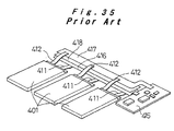
- Fig. 35 is a view of a conventional battery pack including a parallel-connection of three lithium polymer rechargeable batteries 401 having an outer case of a laminated sheet, and the batteries are connected to a circuit board 415 having a battery protection circuit.
- the battery pack is stored in a pack case to complete the battery pack.
- the positive and negative electrodes of the rechargeable battery 401 are both formed as a metallic foil lead having a thickness of at most 0.1 mm.
- the positive electrode lead 411 is of aluminum and the negative electrode lead 412 is of copper. It is difficult to wire the leads or connect them with a wiring lead. Consequently, in the conventional arrangement, a positive electrode metal plate 416 and a negative electrode metal plate 417 are provided on the sides of an insulating material 418, and the positive electrode leads 411 of the rechargeable batteries 401 are connected to the positive electrode metal plate 416, while the negative electrode leads 412 are connected to the negative electrode metal plate 417.
- the positive and negative electrode metal plates 416 and 417 are connected to the circuit board 415 having the battery protection circuit, so that the rechargeable batteries 401 are connected in parallel and power is input/output through the battery protection circuit.
- the positive and negative electrode leads 411 and 412 extended from the rechargeable batteries 401 cannot be connected on the same plane, therefore the workability is low and the positive and negative electrode leads 411 and 412 could be damaged during the working.
- the connection of the positive electrode leads 411 to the positive electrode metal plate 416 and the connection of the negative electrode leads 412 to the negative electrode metal plate 417 are in the front-back relation, the positive electrode leads 411 and the negative electrode leads 412 could be in contact with the negative electrode metal plate 417 and the positive electrode metal plate 416, respectively.
- the insulation between the positive electrodes and the negative electrodes must be enhanced.
- the metal plates 416 and 417 for the positive and negative electrodes are contacted with the rechargeable batteries 401 because of impact or vibration, the outer case made of a laminated sheet could be damaged.
- the rechargeable batteries 401 and the positive and negative electrode metal plates 416 and 417 must be secured.
- an insulating member or a securing member must be provided at the pack case, which increases the number of necessary members and the number of steps.
- a battery power source device includes rechargeable batteries having an outer case made of a soft laminated sheet and is subjected to impact or vibration
- the rechargeable batteries could be moved by the weight of the power generating element, which could break off or bend the foil lead extended to the outside from the outer case or the outer case could be damaged. It is therefore a common practice to secure the rechargeable battery to the inner surface of the pack case with a double-faced adhesive tape.
- the strength of securing the power generating element by the outer case is lower than a rechargeable battery storing a power generating element in a metallic case.
- the power generating element stored inside could move, which could cause the leads extended from the positive and negative electrode plates to break off or bend in the outer case.
- the double-faced adhesive tape used to secure the rechargeable battery at the mounting position often damages or scars the outer case when a lining sheet is removed from the tape, and the appearance or reliability of the rechargeable battery could be degraded.
- the work of removing the lining sheet lowers the workability.
- the rechargeable battery becomes thicker because the outer case is made of a soft material.
- the pack case storing the rechargeable battery could deform or the device provided with the battery pack could adversely be affected.
- the soft outer body tends to be scarred or deformed.
- a battery power source device is constituted with a plurality of rechargeable batteries
- the rechargeable batteries and a circuit board having a battery protection circuit and the like must be integrated, and the elements therefor must be stored in a pack case, which impedes further reduction in the thickness and weight of the battery power source device.
- the positive and negative electrode leads are made of a metal foil, and therefore the leads could be disconnected by vibration in ultrasonic welding to join them to the circuit board.
- the added thickness of the circuit board reduces the advantage that the rechargeable batteries are thin.
- combining the circuit board also increases the plane space, and the size of a device to install such a battery pack could not be reduced as desired accordingly.
- An object of the present invention is to provide a rechargeable battery directed to a solution to the above-described disadvantages when a battery power source device is composed of a rechargeable battery having an outer case made of a laminated sheet, a method of joining leads therefor, and a battery power source device using such rechargeable batteries.
- a battery power source device includes a plurality of rechargeable batteries storing a power generating element in an outer case made of a laminated sheet and formed in a flat, approximately prismatic shape. Positive and negative electrode leads of the rechargeable batteries are extended in the same direction from the same lead extended edge of the outer case thermally sealed.
- the plurality of rechargeable batteries are arranged in parallel so that their lead extended edges are in the same direction, and the device includes a circuit board including a conductive pattern and a battery protection device formed thereon.
- the circuit board is provided on the lead extended edge of each rechargeable battery, the positive and negative electrode leads of each rechargeable battery are joined to a prescribed conductive pattern formed in the extending direction of each lead on the same surface of the circuit board, so that a connection circuit formed by the conductive pattern on the circuit board connects each rechargeable battery to an input/output terminal through the battery protection device.
- the positive and negative electrode leads of the plurality of rechargeable batteries are connected to the conductive pattern formed in the lead extending direction, on the same plane on the circuit board, so that the foil type leads having little strength are free from bending or torsion.
- a battery power source device includes a plurality of rechargeable batteries stored in a pack case.
- the rechargeable battery stores a power generating element in an outer case made of a laminated sheet and is formed in a flat, approximately prismatic shape.
- the positive and negative electrode leads of the batteries are extended in the same direction from the same lead extended edge of the outer case.
- the plurality of rechargeable batteries are positioned and provided in parallel in the pack case so that their lead extending directions are in the same direction.
- a circuit board including a conductive pattern and a battery protection device thereon is positioned and provided on the lead extended edge of the rechargeable batteries, and the positive and negative electrode leads of each rechargeable battery are joined to a prescribed conductive pattern formed in the extending direction of each lead on the same surface of the circuit board, so that a connection circuit formed by the conductive pattern on the circuit board connects each the rechargeable battery to an input/output terminal through the battery protection device.
- the positive and negative electrode leads of the plurality of rechargeable batteries are connected to the conductive pattern formed in the lead extending direction on the same plane on the circuit board provided on the lead extended edge, so that the leads are not subjected to bending force shifted from the extending direction, and the leads having low mechanical strength are free from damages.
- the leads By connecting the leads to the circuit board, the leads are connected to the input/output terminal through the battery protection device by the connection circuit based on the conductive pattern formed on the board, and therefore the disadvantages associated with poor workability or insulation using wiring members such as wiring leads or metal plates for connecting the positive and negative electrodes of the plurality of rechargeable batteries are solved.
- the circuit as a battery pack is formed at well.
- a battery power source device includes a plurality of rechargeable batteries stored in a pack case.
- the rechargeable battery stores a power generating element in an outer case made of a laminated sheet and is formed in a flat, approximately prismatic shape.
- the pack case includes upper and lower cases formed in a pair of halves, and the upper and lower cases have position restriction walls to restrict the position to store rechargeable batteries around the side surfaces of the plurality of rechargeable batteries.
- the lower case storing the plurality of rechargeable batteries is joined with the upper case between the position restriction walls and side peripheral walls for integrating both cases.
- the sides of the rechargeable battery formed in a flat, prismatic shape are surrounded by the position restricting wall, and both flat surfaces are in abutment against the upper and lower cases. Consequently, impact or vibration does not cause the rechargeable battery to move, so that faults associated with such movement are prevented.
- the surfaces of the upper case and/or the lower case in contact with the flat surfaces of the plurality of rechargeable batteries may be formed into an elastic deforming surface that is thinner than their periphery and that elastically deforms in accordance with a change in the thickness of the rechargeable battery.
- a lead joining method includes the steps of providing a lead made of a metal foil on a land formed by a conductive pattern on a surface of a circuit board, supporting a back surface of the circuit board by an anvil of an ultrasonic welder, and abutting a welding tip against the lead and applying ultrasonic vibration to the welding tip as the tip presses toward the anvil, thereby connecting the lead to the land by ultrasonic joining.
- the lead is connected to the land by ultrasonic joining using the welding tip, so that if the lead is of a material not suited for soldering, the lead is directly joined to the land.
- the use of a medium member for soldering is eliminated, thereby reducing wastes and the number of steps.
- a battery power source device includes a rechargeable battery and a circuit board having a power source circuit including a battery protection circuit, and positive and negative electrode leads of a metal foil extended from the rechargeable battery are connected to prescribed lands formed by a conductive pattern on a surface of the circuit board by ultrasonic joining, respectively.
- the lead is connected to the land on the circuit board by ultrasonic joining, and the use of a medium member for soldering is not necessary, thereby reducing wastes and the number of steps.
- a battery power source device includes a lithium polymer rechargeable battery and a circuit board having at least a battery protection circuit thereon.
- the rechargeable battery stores a power generating element in an outer body made of a pair of laminated sheets that are thermally sealed at peripheries thereof.
- the rechargeable battery is formed in a plate shape whose positive and negative electrode leads are extended from a lead extended edge.
- the rechargeable battery and the circuit board are integrated, and the lithium polymer rechargeable battery is secured on a metal plate.
- a battery having a soft outer body prone to damages or deformation is secured to a metal plate for protection, which is particularly effective in integrating a plurality of batteries with a circuit board.
- a battery power source device includes a rechargeable battery and a circuit board having a power source circuit.
- the rechargeable battery stores a power generating element in an outer case made of a pair of laminated sheets having their peripheries sealed by welding and is formed in a flat, approximately prismatic shape.
- Positive and negative electrode leads of the battery are extended from a lead extended edge sealed by welding.
- the positive and negative electrode leads are connected in prescribed positions on the circuit board, respectively, and the circuit board is provided on the lead extended edge and attached and secured to the rechargeable battery by an adhesive sheet. Since the circuit board is provided in a space at the lead extended edge of the rechargeable battery and secured by an adhesive sheet, the circuit board and the rechargeable battery are integrated in the power source device without increasing the volume of the rechargeable battery.
- a rechargeable battery stores a power generating element in an outer case made of a pair of laminated sheets having their peripheries sealed by welding and is formed in a flat, approximately prismatic shape. Positive and negative electrode leads of the battery are extended from a lead extended edge sealed by welding.
- a double-faced adhesive sheet to secure the rechargeable battery in a prescribed position is attached on a flat surface of the rechargeable battery.
- a lining sheet of the double-faced adhesive sheet has a part on the backside that is not provided with an adhesive at an arbitrary side of the adhesive sheet. Since the lining sheet is readily removed, the outer case of the rechargeable battery is prevented from being damaged or scarred.
- a battery power source device includes a rechargeable battery and a circuit board.
- the rechargeable battery stores a power generating element in an outer case made of a pair of laminated sheets having their peripheries sealed by welding and is formed in a flat, approximately prismatic shape.
- Positive and negative electrode leads of the battery are extended from a lead extended edge sealed by welding.
- the circuit board has a land to which each of the positive and negative electrode leads is joined by ultrasonic welding.
- the rechargeable battery and the circuit board are positioned and provided such that the leads are bent at the time of the ultrasonic welding and securing to a prescribed position. Since the leads are bent, when vibration or impact is applied, the amplitude is absorbed by the bent portion and the leads having small strength are prevented from being broken.
- a battery back includes an arrangement of three rechargeable batteries 1 connected in parallel.
- the rechargeable battery 1 stores a power generating element in an outer case made of a laminated sheet.
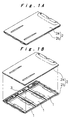
- three rechargeable batteries 1 and a circuit board 3 are stored in a lower case 2b of a pack case 2, and an upper case 2a is joined to the lower case 2b to constitute a flat battery pack as shown in Fig. 1A.
- the rechargeable battery 1 is a lithium polymer rechargeable battery, and has as an outer body of a laminated sheet produced by covering both surfaces of a metal layer with a plurality of resin layers.
- a power generating element is stored in a recess 29 formed at one side of the laminated sheet to be folded into two.
- three seal edges P1, P2, and P3 are thermally sealed to form an outer case 4
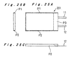
- positive and negative electrode leads 11 and 12 connected to positive and negative electrode plates, respectively of layered electrode plates 30 forming the power generating element are extended outside from the seal edge P3 of the outer case 4.
- the seal edges P1 and P2 on both sides of the outer case 4 are folded and secured with an adhesive tape 31 on the flat surface as shown in Fig. 2C, so that the width is reduced.
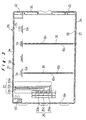
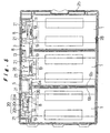
- the rechargeable batteries 1 are provided in the space surrounded by battery positioning ribs 6a and 6b and an inner circumferential wall 28 formed in the lower case 2b such that the positive and negative electrode leads 11 and 12 are directed to the circuit board 3.
- the rechargeable batteries are thus positioned and secured in a prescribed position in the pack case 2 as the upper case 2a is joined to the lower case 2b as will be described.
- the circuit board 3 is positioned in the space surrounded by substrate positioning ribs 7a and 7b formed on the lead extended edge of the rechargeable batteries 1 and the inner circumferential wall 28.
- the substrate positioning ribs 7a and the inner circumferential wall 28 position the circuit board 3 by surrounding the board.
- the substrate positioning rib 7b is fitted into an elliptical positioning hole 23 formed in a substrate 10, so that the circuit board 3 is held not to be shifted in the position.
- the circuit board 3 has a conductive pattern 9 on both surfaces of the substrate 10, and the patterns on the front and back surfaces are connected by through holes 13 located in prescribed positions.
- a connection circuit for connecting electronic parts provided on the substrate 10 with a circuit and for connecting the three rechargeable batteries 1 in parallel is formed.
- the circuit board 3 is connected with the positive and negative electrode leads 11 and 12 of the three rechargeable batteries 1.
- the positive and negative electrode leads 11 and 12 of each rechargeable battery 1 have their tip end ultrasonic-welded with a connection member 19 made of a nickel plate, and the connection member 19 is then soldered to a soldering land 21 made of the conductive pattern 9 on the substrate 10.
- the three rechargeable batteries 1 are connected to the circuit board 3.
- the connection member 19 is used because connection strength greater than that by the ultrasonic welding that might adversely affect the protection circuit at the time of welding or the spot welding that might damage the mechanically weak foil type leads. In addition, this is because soldering could readily be accomplished.
- soldering lands 21 corresponding to the positive and negative electrode leads 11 and 12 are both in the lead extending direction on the same plane on the substrate 10.
- the connection members 19 connected to the positive and negative electrode leads 11 and 12 of rechargeable batteries 1 are positioned on the soldering lands 21. Consequently, the operation of soldering the positive and negative electrode leads 11 and 12 to the circuit board 3 is readily accomplished.
- connection member 19 is used, while other methods such as directly connecting the negative electrode leads 12 of copper for example to the soldering lands 21 on the circuit board 3 may be employed.
- the conductive pattern 9 for connecting the plurality of rechargeable batteries 1 is formed on the back surface of the circuit board 3, and the soldering lands 21 for connecting the positive and negative electrode leads 11 and 12 of each rechargeable battery 1 are formed on the surface of the circuit board 3, while the opposite electrodes are separated both two- and three-dimensionally by the substrate 10.
- This arrangement is effective in keeping the insulation between the positive and negative electrodes, and an additional insulating member is eliminated.
- the rechargeable batteries 1 are connected in parallel as they are each connected in series with an overcurrent protection element 8, and the parallel connection of the three rechargeable batteries 1 is connected to a connection terminal 20 through a protection circuit 5.
- the overcurrent protection element 8 fuses to protect each rechargeable battery 1 against damages when overcurrent is passed through the rechargeable battery 1.
- the protection circuit 5 includes a plurality of electronic parts including IC parts provided collectively in a prescribed position on the substrate 10, and serves to protect the rechargeable batteries 1 against an abnormal state for a battery pack such as overcharge and overdischarge by disconnecting the input/output circuit in response to such an abnormal state.
- the protection circuit 5 has their elements provided collectively in a prescribed position, and thus can be coated with a resin mold 26 in one location as shown in Figs. 4A and 4C.
- a battery protection device includes these overcurrent protection element 8 and protection circuit 5 and prevents the rechargeable batteries 1 from being damaged by failure or erroneous operation or wrong use of the device connected to the battery pack.
- the overcurrent protection element 8 has two protection functions.
- the first function is to discharge considerably large discharge current from the rechargeable batteries 1 when the protection circuit 5 is defective or damaged for example by short-circuit and the region between the positive and negative input/output terminals is short-circuited by some extraneous cause.
- the overcurrent protection element 8 fuses to prevent excessively large current.
- the second function is a protection function when one of the rechargeable batteries 1 connected in parallel is internally short-circuited.
- the internal short circuit refers not only to the condition caused by simple defects in the battery but also to that caused by abnormal handling.
- an overcurrent fusing type fuse tip is suitably provided to the circuit board 3, and is provided near each of the rechargeable batteries 1.
- a PTC (Positive Temperature Coefficient) element can be used for overcurrent protection.
- an external input/output terminal 25 including a positive input/output terminal 25a, a negative input/output terminal 25b, and a temperature detecting terminal 25c is provided at the lower case 2b as the contact surfaces are exposed to the outside.
- the terminals 25a, 25b, and 25c are respectively joined with a positive lead plate 22a, a negative lead plate 22b, and a temperature detection lead plate 22c forming a lead plate 22. Each one end of the terminals is under the position to provide the circuit board 3.
- the corresponding ends of the lead plate 22 are inserted to holes of a positive connection terminal 20a, a negative connection terminal 20b, and a temperature detection connection terminal 20c forming the connection terminal 20 on the circuit board 3.
- the lead plate 22 and the connection terminal 20 are connected by soldering and the circuit board 3 is thus connected to the external input/output terminal 25.
- charge/discharge to/from the rechargeable batteries 1 is performed through the circuit board 3 from the external input/output terminal 25.
- the upper case 2a is joined to the lower case 2b by ultrasonic joining as shown in Figs. 1A and 1B, and a battery pack including the plurality of rechargeable batteries 1 enclosed in the pack case 2 is provided. How the lower and upper cases 2a and 2b are joined will now be described.
- the upper case 2a is provided with a side circumferential rib 33 fitted into a side circumferential groove 34 formed between the inner and outer circumferential walls 28 and 27 of the lower case 2b, battery holding ribs 36 fitted into battery holding grooves 35 formed between the battery positioning ribs 6b formed at the lower case 2b, lead edge holding ribs 37 fitted between the battery positioning ribs 6a and the substrate positioning ribs 7a formed at the lower case 2b, and substrate pressing ribs 38 for restricting the position of the circuit board 3 in the thickness-wise direction.
- Positioning ribs 39 formed at three corner positions fit with positioning portions 40 formed at the lower case 2b.
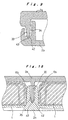
- the positioning ribs 39 are inserted into the positioning portions 40 at the lower case 2b to position the upper case 2a to the lower case 2b. Then, as shown in Fig. 9, when the upper case 2a is pressed toward the lower case 2b, the side circumferential rib 33 is fitted into the side circumferential groove 34, while as shown in Fig. 10, the battery holding rib 36 is fitted into the battery holding groove 35 and the lead edge holding rib 37 is fitted between the battery positioning rib 6a and the substrate positioning rib 7a, so that a V-shaped rib 42 formed at the rib tip is fitted into a V-shaped groove 43 formed at the bottom of the groove.
- the upper and lower cases 2a and 2b are held and pressed between the horn of a ultrasonic welder and a receiving jig, and provided with ultrasonic vibration by the horn. Then, the upper and lower cases 2a and 2b are welded between the V-shaped rib 42 and the V-shaped groove 43. In this way, the upper and lower cases 2a and 2b are fitted as the recess and the raised portion are fitted with one another, so that the positioning is surely performed and the rigidity of the pack case 2 is improved as well.
- the tip end of the raised portion is joined by ultrasonic welding at the bottom of the recess, the joint is not exposed to outside, and this processing is performed not only in the periphery but also in positions surrounding the plurality of rechargeable batteries 1. Consequently, the strength against the torsion or bending of the pack case 2 is improved.
- the recess deforms prior to the other part, the deformation is held by the recessed portion, and therefore the rechargeable batteries 1 is less affected. Since the resin fused at the time of welding is rigidly attached at the bottom of the recess, the fused resin does not come out from the joint surface and stick to the rechargeable batteries 1.
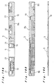
- Figs. 11A and 11B show how the rechargeable batteries 1 are stored in the pack case 2.
- Fig. 11A is a sectional view taken along the width of the rechargeable battery 1
- Fig. 11B is a sectional view taken along the length of the rechargeable battery 1.
- the part of the lower case 2b in contact with the flat surface of the rechargeable battery 1 is formed into a thin, elastic deforming surface 44.
- Fig. 12 is a plan view of the lower case 2b seen from the outside showing the state of how the elastic deforming surface 44 is formed.
- the elastic deforming surface 44 is formed to be thin in a position a step H lower than the periphery and elastically deforms while keeping the flat surface when the thickness of the rechargeable battery 1 changes by expanding.
- the elastic deforming surface 44 is attached with a thin stainless plate 45 to prevent the rechargeable batteries 1 from being pierced with an edge tool or the like and damaged.
- the thin stainless plate 45 has a projection 45a at a corner, which alleviates positioning of the plate when the plate is attached.
- the elastic deforming surface 44 has a part not covered at the four sides, so that the elastic deforming surface 44 is not prevented from deforming. Note that an elastic deforming groove 46 formed to be thin is provided to the rechargeable battery 1 provided where the external input/output terminal 25 is provided so that changes in the thickness of the rechargeable battery 1 is similarly addressed.
- the rechargeable battery 1 having the outer case 4 made of a soft laminated sheet has its thickness evenly increased to press and raise the elastic deforming surface 44.
- the elastic deforming surface 44 deforms at its periphery and is raised within the step H as the central part is kept flat.
- the expanded portion 47 is formed along the length of the rechargeable battery 1 at the inner surface of the upper case 2a.
- the batteries 1 are held between the expanded portion 47 and the elastic deforming surface 44.
- the elastic deforming surface 44 applies force on the rechargeable batteries 1 in the contracting direction by its elasticity, so that the rechargeable batteries 1 are constantly under stress and the expansion of the electrode plate is restricted.
- a rechargeable battery 1 formed with the outer case 4 made of a soft material such as a laminated sheet has only small force to bind layers of electrode plate groups, and the layered electrode plates tend to shift in position in response to impact or vibration. However, the side surfaces are surrounded by the four edges and the stress is applied in the thickness-wise direction, so that the movement of the electrode plates is restricted.
- a plurality of rechargeable batteries 1 are connected in parallel to increase the battery capacity. Meanwhile, when relatively high voltage is required by a device to which the battery is to be applied, a plurality of rechargeable batteries 1 may be connected in series to the circuit board 3 as shown in the circuit diagram in Fig. 7. In the same battery pack arrangement, higher voltage is supplied.
- a plurality of rechargeable batteries 1 may be arranged on both sides of a circuit board 24.
- a plurality of rechargeable batteries 1 may be arranged in a single row, the circuit board 24 may be elongated accordingly, and a battery pack in a strip shape may be formed.
- a plurality of rechargeable batteries 1 need only be arranged corresponding to the device to be provided with the battery, so that various arrangements may be achieved corresponding to the device based on the above-described arrangement.
- the arrangement having a plurality of rechargeable batteries 1 connected to the circuit board 3 is stored into the pack case 2 and formed into a battery pack as described above. Meanwhile, battery packs in an arrangement having a plurality of rechargeable batteries 1 connected to the circuit board 3 may be produced as separate products and may be supplied to the manufacturer of the devices.
- rechargeable batteries 1 are connected to a circuit board 70.
- the circuit board 70 has the same configuration as that of the circuit board 3, and the rechargeable batteries 1 are similarly connected in parallel.
- a connection terminal 20 of the circuit board 70 is connected with a connector 49 through a lead. The connector is used to connect the terminal to the device.
- Figs. 15A and 15B when the circuit board 70 is provided on the lead extended edge of the rechargeable batteries 1 after the batteries 1 and the circuit board 70 are connected, the volume of the battery pack is reduced, and the positive and negative electrode leads 11 and 12 of the rechargeable batteries 1 are prevented from being exposed and protected.
- a battery pack in the arrangement as shown in Figs. 15A and 15B is integrated by shrink-packing with a thin resin sheet or by securing with an adhesive or an adhesive tape, so that it is prevented from being damaged during handling or transfer to the device manufacturer.
- the battery pack is provided in a mounting position for the pack in the device, and attached in electrical connection with the device through the connector 49.
- a battery pack according to the second embodiment has a parallel connection of three rechargeable batteries 1 having a power generating element stored in an outer case made of a laminated sheet.
- the positive and negative electrode leads 11 and 12 extended from the rechargeable battery 1 are connected to the circuit board 3 by ultrasonic-welding the connection member 19 made of a nickel plate to their tip ends and soldering the connection member 19 to the soldering land 21 of the circuit board 3.
- the positive and negative electrode leads 11 and 12 are directly connected to the soldering land 21 by ultrasonic-welding, and this lead connection method will be described.
- a circuit board 80 to which the positive and negative electrode leads 11 and 12 are directly connected has soldering lands 21 formed by a conductive pattern on the front surface side of a substrate 10, and electronic parts forming a battery protection circuit are provided.
- a connection pattern to connect three rechargeable batteries 1 in parallel is formed on the back surface side of the substrate 10, and the conductive patterns on the front and back surface sides are connected by through holes 13 in prescribed locations.
- solder resist 84 As hatched in the figure, the part other than the soldering lands 21 and the soldering part on the front surface side is covered with solder resist 84.
- the part other than the backside position of the soldering lands 21 is covered with the solder resist 84.
- the part on the backside of the soldering lands 21 that is not necessary for forming the circuit has connection lands 85 and 86 by a conductive pattern.
- the front side covered with resin mold 5 has IC parts forming the battery protection circuit buried therein.
- the six soldering lands 21 formed at the circuit board 80 are connected with the positive and negative electrode leads 11 and 12 of the rechargeable batteries 1 by ultrasonic joining.
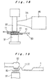
- the circuit board 80 is provided on the anvil 91 of an ultrasonic welder, the positive electrode lead 11 is placed on and pressed against the soldering land 21 by prescribed pressure using a welding tip 92.
- ultrasonic vibration of a ultrasonic vibrator 95 is applied to the welding tip 92 through a horn 94, and then the friction at both contacting interfaces between the positive electrode lead 11 and the soldering land 21 destroys any oxide film on the surface and causes plastic deformation, so that newly generated metal surfaces are closely adhered.
- the backside part of the circuit board 80 in contact with the anvil 91 has a conductive pattern of a copper foil, so that the solder resist 84 is not applied on the surface. Then, the friction coefficient between the anvil 91 and the conductive pattern is large, and thus the slipping between the anvil 91 and the circuit board 80 is restricted when ultrasonic vibration is applied. Thereby, the vibrating time is reduced and efficient ultrasonic welding is achieved. If there is no such conductive pattern at the backside part of the circuit board 80 in contact with the anvil 91, the slipping caused between the substrate 10 and the anvil 91 prevents a stable joining from being provided because the substrate 10 made of a glass-cloth reinforced epoxy resin or the like has a hard and smooth surface.
- the surface of the soldering land 21 is provided with a nickel plating as thick as 2 to 3 ⁇ m, and a gold plating having a thickness of about 0.05 ⁇ m is provided thereon. In this way, an oxide film hardly forms on the joint surface, and the close contact with the positive electrode lead 11 or the negative electrode lead 12 is achieved, which allows efficient ultrasonic joining.
- the rechargeable batteries 1 are arranged so that the positive and negative electrode leads 11 and 12 are bent.
- the positive and negative electrode leads 11 and 12 made of a low strength, metal foil are thus bent, they are prevented from being broken by the ultrasonic vibration. More specifically, since the amplitude of the ultrasonic vibration is absorbed by the bent part of the positive and negative electrode leads 11 and 12, force applied in the tensile direction upon the leads 11 and 12 does not break them.
- the three rechargeable batteries 1 having the positive and negative electrode leads 11 and 12 joined to the circuit board 80 by the ultrasonic joining and the circuit board 80 are stored in a prescribed position in the lower case 2b forming the pack case as shown in Fig. 17, and the lower case 2b is closed by the upper case 2a to form a battery pack.
- a battery pack according to the embodiment can be mounted at the back surface of an LCD (Liquid Crystal Display) for a mobile personal computer.
- LCD Liquid Crystal Display
- a battery pack 101 includes three rechargeable batteries 102 formed as a lithium polymer rechargeable battery, and a circuit board 103 including a battery protection circuit, a communication circuit for communication with the mobile computer, and the like.
- the rechargeable batteries 102 and the circuit board 103 are secured to an aluminum plate (metal plate) 105 and integrated.
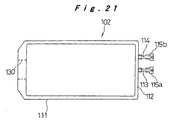
- the rechargeable battery 102 is produced by storing and enclosing a power generating element in an outer body 111 by thermally sealing the peripheries, extending positive and negative electrode leads 113 and 114 to the outside from one lead extended edge 112 thermally sealed, and cutting the outer shape into a prescribed shape.
- the outer body 111 is made of a laminated sheet produced by joining a resin sheet to both sides of an aluminum foil.
- the positive electrode lead 113 is made of an aluminum foil, while the negative electrode lead 114 is made of a copper foil.
- connection plates 115a and 115b made of nickel are joined to the tip ends of the positive and negative electrode leads 113 and 114 by ultrasonic welding.
- the rechargeable battery 102 is adhesively secured onto the aluminum plate 105 by a double-faced adhesive tape. At the time, an insulation coating is provided on the surface of the aluminum plate 105, or an insulating sheet is provided between the rechargeable battery 102 and the aluminum plate 105 for electrical insulation.
- the outer body 111 of the rechargeable battery 102 is made of a laminated sheet produced by joining a resin sheet on both sides of an aluminum foil as described above. The aluminum foil is exposed at the cutting end of the outer shape, and the exposed part is insulated by the insulation coating or by the insulating sheet so that it does not contact the aluminum plate 105.
- Fig. 22 shows the back surface side of the aluminum plate 105, and the adhesion surface of the rechargeable battery 102 has openings 108, so that the aluminum plate 105 is reduced in weight and that the temperature of the rechargeable batteries 102 is equalized.
- the rechargeable batteries 102 are secured to the aluminum plate 105, so that the rechargeable batteries 102 having the soft outer body 111 prone to damages or deformation are protected. Since the plurality of rechargeable batteries 102 and the circuit board 103 are integrated on the aluminum plate 105, the rigidity is improved as the thickness is reduced.
- An upper end portion of the aluminum plate 105 is attached with an insulating paper sheet 109, on which the circuit board 103 is attached and secured. Soldering lands for connecting batteries (not shown) formed at the circuit board 103 are soldered with the connection plates 115a and 115b joined to the positive and negative electrode leads 113 and 114 of the rechargeable battery 102, respectively.
- a thermistor (temperature detecting sensor) 106 is secured to the corner of the part storing the power generating element of the rechargeable battery 102 where the seal edge is raised, the lead is connected to the circuit board 103, and the temperature of the battery is detected.
- the thermistor 106 Since the thermistor 106 is secured in the above-described position, the thermistor 106 detects the temperature of the battery by contacting the power generating element in a prescribed state through the outer body 111 even if the outer body 111 is expanded for some cause such as a gas generated in the outer body 111.
- a liquid absorbing sheet 107 is adhered on the lead extended edge 112 of each rechargeable battery 102, and the connection plates 115a and 115b formed by folding the positive and negative electrode leads 113 and 114 are provided thereover.
- the lead extended edge 112 tends to have its sealing strength weakened as the positive and negative electrode leads 113 and 114 pass therethrough during thermal sealing, or a safety vent 130 to relieve increased internal pressure is provided, therefore the electrolyte solution could leak outside the outer body 111, and a liquid absorbing sheet 131 is provided in the position.
- the liquid absorbing sheets 107 and 131 absorb the leaking electrolyte solution if any, and consequently the device to which the battery pack 101 is mounted is not affected.
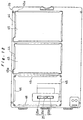
- the battery pack 101 in the above arrangement is mounted in the display panel 117 of a mobile personal computer as shown in Figs. 23A, 23B and 24.
- Fig. 23A is a view of the backside of the display panel 117
- Fig. 23B is a sectional view taken along the line XXIIIB-XXIIIB
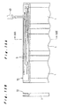
- Fig. 24 is an enlarged sectional view thereof.
- the open front surface of a box 119 for the display panel 117 is provided with an LCD 118, at the backside of which the battery pack 101 is provided with the aluminum plate 105 facing the backside.
- the aluminum plate 105 of the battery pack 101 has a good heat transfer characteristic and therefore the heat is efficiently dissipated, while unbalanced temperature distribution i.e., temperature rise only in a part of the plurality of rechargeable batteries 102 is prevented.
- the openings 108 formed in the aluminum plate 105 have their position and size set appropriately differently among locations with high temperature rise by extraneous causes such as the provision of the LCD 118 and the other locations. Thus, the temperatures of the plurality of rechargeable batteries 102 are equally maintained.
- a battery pack according to the embodiment includes lithium polymer rechargeable batteries having an outer case made of a laminated sheet and a circuit board including a battery protection circuit for protecting the rechargeable battery against overcharge/overdischarge.
- the rechargeable batteries and the circuit board are integrally formed.
- a rechargeable battery 201 is the same as the rechargeable battery 1 described in conjunction with the above embodiments, while seal edges are processed differently. As shown in Fig. 25B, the seal edges P1 and P2 on both sides are wound inside to reduce the width size and improve the sealing effect, and adapted to a battery pack.
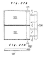
- Figs. 26A to 26D show the structure of a battery pack A that includes two rechargeable batteries 201 having the above structure and a circuit board 206.
- the batteries and the circuit board are integrated, and a connector 209 to connect the battery pack A to the device to use the battery is extended from the circuit board 206. The process of how to assemble this battery pack will be described.
- the circuit board 206 has a connection pattern used to connect the two rechargeable batteries 201 in series or parallel and a battery protection circuit for protecting the rechargeable batteries 201 against overcharge/overdischarge.
- the positive and negative electrode leads 11 and 12 of each rechargeable battery 201 are connected to a land formed on the circuit board 206.
- the positive electrode lead 11 is made of an aluminum foil
- the negative electrode lead 12 is made of a copper foil.
- the positive electrode lead 11 cannot readily be soldered to the land, and therefore the positive and negative electrode leads 11 and 12 are welded to the land by ultrasonic welding, or the leads are welded to a nickel plate by ultrasonic welding followed by soldering the nickel plate to the land.
- Each lead wire of the connector 209 is connected in a prescribed position of the circuit board 206 by soldering.
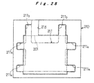
- the assembling jig 210 has a positioning recess 213 formed corresponding to the shape of the two rechargeable batteries 201 and a backside adhesive sheet 211.
- the backside adhesive sheet 211 cut into a shape as denoted by the virtual line is positioned on the positioning recess 213 so that the adhesive surface faces up.
- two rechargeable batteries 201 connected with the circuit board 206 are pressed onto the adhesive sheet 211.
- the positioning recess 213 has its central part having a size and shape defined as the two rechargeable batteries 201 are closely contacted at their side surfaces. Accordingly, the two rechargeable batteries 201 have their side surfaces in a close contact state.
- binding pieces 211a, two each branching on the right and left sides of the backside adhesive sheet 211 are attached on the front side from the side surfaces of the rechargeable batteries 201, and the circuit board 206 is pressed by two board securing pieces 211b branching from the upper side to be attached to the front surface of the rechargeable batteries 201.
- a front surface adhesive sheet 212 between the two closely contacted rechargeable batteries 201 is attached on the front surface side, and then as shown in Figs. 26A to 26D, the two rechargeable batteries 201 and the circuit board 206 are integrated into a battery pack A.
- the battery pack A thus integrated has the two rechargeable batteries 201 integrally connected in a wide surface of the back surface adhesive sheet 211, and the four binding pieces 211a bind the seal edges P1 and P2 of the rechargeable batteries 201.
- the expansion of width by the elasticity is prevented, and the sealing characteristic is improved.
- the board securing pieces 211b secure the circuit board 206 on the lead extended edge P3 to integrate the rechargeable batteries 201 and the circuit board 206.
- a battery pack B according to the embodiment will now be described in conjunction with Figs. 29A to 29D and Fig. 30. Note that the same elements as those of the battery pack A are denoted with the same reference numerals and will not be described.
- two rechargeable batteries 201 are connected by an adhesive at the side surfaces in contact with each other.
- a double-faced adhesive tape is used as the adhesive.
- the positive and negative electrode leads 11 and 12 of the two rechargeable batteries 201 are connected to the circuit board 206, which is provided on the lead extended edge P3 of the two rechargeable batteries 201.
- Two binding members 204 and 205 are attached to surround the side periphery of the two rechargeable batteries 201.
- the binding members 204 and 205 are produced by bending into a U shape a resin plate having a width the same as a thickness of the rechargeable batteries 201 and attaching an adhesive (double-faced adhesive tape in this case) to the inner side.
- the binding member 204 is provided with a notch 204a through a lead for the connector 209.
- the binding members 204 and 205 are attached to the side surface of the rechargeable batteries 201 as shown in Figs. 29A to 29D, and the two rechargeable batteries 201 are integrated, so that the circuit board 206 can be secured to the rechargeable batteries 201 with an adhesive sheet 214 to complete an integrated battery pack B.
- a rechargeable battery 207 applied to a battery pack C has positive and negative electrode plates forming a power generating element with a larger area, so that a battery capacity equivalent to that of the above two rechargeable batteries 201 connected in parallel is obtained and similarly a laminated sheet is used for the outer case.
- Positive and negative electrode leads (not shown) extended from the lead extended edge P3 of the rechargeable battery 207 are connected with a circuit board 216.
- the circuit board 216 is provided on the lead extended edge P3 and secured to the rechargeable battery 207 by a board securing adhesive sheet 219.
- the seal edges P1 and P2 on both sides of the rechargeable battery 207 are bent to the side surface and secured by a seal edge securing adhesive sheet 218.
- These battery packs A, B, and C described above are provided in a storing position in each device where they are used, and the connector 209 is connected to the device to allow the battery pack to operate as a battery power source device.
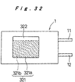
- the rechargeable batteries 1 described in conjunction with the above embodiments are generally secured to a mounting position with a double-faced adhesive sheet and as shown in Fig. 32, a double-faced adhesive sheet 321 is attached at the plane surface.
- the double-faced adhesive sheet 321 is made of an adhesive layer 321b adhered to the plane surface of the rechargeable batteries 1 and a lining sheet 321a covering the adhesive layer 321b. If the lining sheet 321a and the adhesive layer 321b have the same area, it would not be easy to remove the lining sheet 321a, which might cause the soft outer case of the laminated sheet to be damaged or recessed with pressure.
- the lining sheet 321a has a larger area than that of the adhesive layer 321b, so that a tab 322 without the adhesive layer 321b at the backside is located in an arbitrary side of the double-faced adhesive sheet 321.
- the lining sheet 321a can readily be removed with the tab 322, the rechargeable batteries 1 are prevented from being damaged, and the workability in securing the rechargeable batteries 1 improves.
- the positive and negative electrode leads 11 and 12 are ultrasonic-welded to the circuit board 206 as they are bent as shown in Fig. 33A, and the circuit board 206 is secured on the lead extended edge of the rechargeable batteries 201 as they remain to be bent as shown in Fig. 33B.
- the rechargeable batteries 1 are provided in a battery position restricting frame 330 and a circuit board 350 is provided in a board position restriction frame 340, the rechargeable batteries 1 and the circuit board 350 are provided such that the positive and negative electrode leads 11 and 12 are bent as shown in Fig. 34B.
- the positive and negative electrode leads 11 and 12 are bent in this way, impact is applied if for example the device provided with the battery pack is dropped, and the rechargeable batteries 1 or 201 deform because their outer case is soft, the bent part of the positive and negative electrode leads 11 and 12 absorbs the deformation, and the positive and negative electrode leads 11 and 12 are not broken
- the battery pack is assembled and the circuit board 206 is reversed and moved onto the lead extended edge of the rechargeable batteries 201, extreme tensile force is not applied upon the positive and negative electrode leads 11 and 12, so that the leads are prevented from being broken.
- the batteries when a battery power source device is assembled using a plurality of rechargeable batteries having an outer case made of a laminated sheet, the batteries are readily connected in parallel or series without damaging foil type leads extended from the rechargeable batteries.
- the connection is made on the circuit board, and therefore the rechargeable batteries and the circuit board do not have to be connected with a separate wiring member, which improves the workability. Consequently, the invention is useful in providing a battery power source device having high insulation and durability.
Landscapes
- Chemical & Material Sciences (AREA)
- Chemical Kinetics & Catalysis (AREA)
- Electrochemistry (AREA)
- General Chemical & Material Sciences (AREA)
- Engineering & Computer Science (AREA)
- Manufacturing & Machinery (AREA)
- Microelectronics & Electronic Packaging (AREA)
- Inorganic Chemistry (AREA)
- Battery Mounting, Suspending (AREA)
- Connection Of Batteries Or Terminals (AREA)
- Sealing Battery Cases Or Jackets (AREA)
Abstract
Description
Claims (32)
- A battery power source device comprising a plurality of rechargeable batteries (1), said rechargeable battery storing a power generating element in an outer case (4) made of a laminated sheet and being formed in a flat, approximately prismatic shape, positive and negative electrode leads (11) and (12) being extended in the same direction from a same lead extended side of the outer case thermally sealed, said plurality of rechargeable batteries being arranged in parallel such that their lead extended edges are in the same direction, said power source device comprising a circuit board (70) including a conductive pattern and a battery protection device formed thereon, said circuit board being provided on the lead extended edge of each said rechargeable battery, the positive and negative electrode leads of each said rechargeable battery being joined to a prescribed conductive pattern formed in the extending direction of each lead on the same surface of the circuit board, whereby a connection circuit formed by the conductive pattern on the circuit board connects each said rechargeable battery to an input/output terminal through the battery protection device.
- The battery power source device according to claim 1, wherein
the circuit board (70) to which the leads of the rechargeable batteries (1) are connected is placed on the lead extended edge of the rechargeable batteries arranged in parallel. - A battery power source device comprising a plurality of rechargeable batteries (1) stored in a pack case (2), said rechargeable battery storing a power generating element in an outer case (4) made of a laminated sheet and being formed in a flat, approximately prismatic shape, positive and negative electrode leads (11) and (12) of the batteries being extended in the same direction from a same lead extended edge of the outer case, the plurality of rechargeable batteries being arranged in parallel in said pack case such that their lead extending directions are in the same direction, a circuit board (3) including a conductive pattern and a battery protection device formed thereon being positioned on the lead extended edge of the rechargeable batteries, the positive and negative electrode leads of each said rechargeable battery being joined to a prescribed conductive pattern formed in the extending direction of each lead on the same surface of the circuit board, whereby a connection circuit formed by the conductive pattern on the circuit board connects each said rechargeable battery to an input/output terminal through the battery protection device.
- The battery power source device according to claim 3, wherein the battery protection device comprises an overcurrent protection element (8) connected in series with each said rechargeable battery (1) and a protection circuit for protecting the rechargeable battery against overcharge/overdischarge.
- The battery power source device according to claim 4, wherein
the overcurrent protection element (8) is an overcurrent fusing type fuse. - The battery power source device according to claim 3, wherein
components for forming a protection circuit are collectively provided in a prescribed position of the circuit board (3). - The battery power source device according to claim 3, wherein the connection circuit of the circuit board (3) connects the plurality of rechargeable batteries (1) in parallel.
- The battery power source device according to claim 3, wherein the connection circuit of the circuit board (3) connects the plurality of rechargeable batteries (1) in series.
- The battery power source device according to claim 3, wherein the connection circuit of the circuit board (3) connects the plurality of rechargeable batteries (1) in series-parallel.
- A battery power source device comprising a plurality of rechargeable batteries (1) stored in a pack case (2), said rechargeable battery storing a power generating element in an outer case (4) made of a laminated sheet and being formed in a flat, approximately prismatic shape, said pack case including upper and lower cases (2a) and (2b) formed in a pair of halves, the upper and lower cases having position restriction walls to restrict a position to store the rechargeable batteries, the walls being formed around side surfaces of the plurality of rechargeable batteries, the lower case storing the plurality of rechargeable batteries being joined with the upper case between said position restriction walls and side circumferential walls for integrating both cases.
- The battery power source device according to claim 10, wherein
projecting walls and the side circumferential walls facing each other between the upper case (2a) and the lower case (2b) have a recessed portion on one side, and a raised portion to be fitted into the recessed portion on the other side. - The battery power source device according to claim 11, wherein
a V-shaped groove having a V-shaped section is formed at a bottom of the recessed portion, a V-shaped rib having a V-shaped section to be fitted with said V-shaped groove is formed at a tip end of the raised portion, and the recessed portion and the raised portion are joined between the V-shaped groove and the V-shaped rib by ultrasonic welding. - The battery power source device according to claim 10, wherein
a height of a battery storing space between the upper case (2a) and the lower case (2b) is smaller than a thickness of the rechargeable battery (1). - A battery power source device comprising a plurality of rechargeable batteries (1) stored in a pack case (2), said rechargeable battery (1) storing a power generating element in an outer case (4) made of a laminated sheet and being formed in a flat, prismatic shape, said pack case including an upper case (2a) and a lower case (2b) formed in a pair of halves, position restriction walls to restrict a position to store the rechargeable batteries, the walls being formed around side surfaces of the plurality of rechargeable batteries at the upper and lower cases, surfaces in contact with flat planes of the plurality of rechargeable batteries at the upper case and/or the lower case being formed into an elastic deforming surface elastically deforming corresponding to a change in a thickness of the rechargeable batteries, the lower case storing the plurality of rechargeable batteries being joined to the upper case between said position restriction walls and side circumferential walls for integrating both cases.
- The battery power source device according to claim 14, wherein a metal thin plate is attached to an outer surface of the elastic deforming surface.
- A lead joining method comprising the steps of providing a lead made of a metal foil on a land (21) formed by a conductive pattern at a surface of a circuit board (80), supporting a back surface of the circuit board by an anvil (91) of a ultrasonic welder, abutting a welding tip (92) against said lead, applying ultrasonic vibration to said welding tip as said welding tip presses toward the anvil, and joining said lead to said land by ultrasonic welding.
- The lead joining method according to claim 16, wherein
the land (21) is produced by plating a copper surface with nickel and then with gold. - The lead joining method according to claim 16, wherein
a copper conductive pattern is formed in a backside position of the circuit board (80) against which the anvil (91) abuts, and the surface is exposed and not coated with solder resist. - A battery power source device comprising a rechargeable battery (1) and a circuit board (80) having a power source circuit including a battery protection circuit, positive and negative electrode leads of a metal foil extended from the rechargeable battery being joined by ultrasonic welding to a prescribed land (21) formed by a conductive pattern on a surface of said circuit board.
- The battery power source device according to claim 19, wherein
IC parts forming the battery protection circuit are secured to the circuit board (80) by resin mold. - A battery power source device comprising a rechargeable battery (102) storing a power generating element in an outer body made of a pair of laminated sheets, said pair of laminated sheets being thermally sealed at peripheries thereof, said rechargeable battery being formed in a plate shape whose positive and negative electrode leads (114) and (115) are extended to the outside from one lead extended edge; and a circuit board (103) having at least a battery protection circuit, said rechargeable battery and said circuit board being integrated, said rechargeable battery being secured on a metal plate (105).
- The battery power source device according to claim 21, wherein
the rechargeable battery (102) and/or the metal plate (105) are/is provided with an insulator for electrically insulating them. - The battery power source device according to claim 22, wherein
the insulator is an insulating coating provided on a surface of the metal plate (105). - The battery power source device according to claim 22, wherein
the insulator is an insulating sheet attached to the rechargeable battery (102) or the metal plate (105). - The battery power source device according to claim 21, further comprising a temperature detecting sensor (106), for detecting a battery temperature, secured to a corner of a part storing the power generating element of the rechargeable battery (102) where a seal edge of the rechargeable battery (102) is raised.
- The battery power source device according to claim 21, further comprising a liquid absorbing sheet attached at a safety vent forming edge and the lead extended edge of the rechargeable battery (102).
- A battery power source device comprising a rechargeable battery (201) and a circuit board (206) having a power source circuit, said rechargeable battery storing a power generating element in an outer case made of a pair of laminated sheets having their peripheries sealed by welding and being formed in a flat, approximately prismatic shape, positive and negative electrode leads of the battery being extended to the outside from one lead extended edge sealed by welding,
said positive and negative electrode leads being connected in prescribed positions on said circuit board, the circuit board being provided on said lead extended edge, the circuit board being attached and secured to the rechargeable battery by an adhesive sheet. - The battery power source device according to claim 27, wherein
a plurality of the rechargeable batteries (201) are arranged in parallel, have their lead extended edges arranged on the same plane and in the same direction, and are secured in parallel by an adhesive sheet. - A battery power source device comprising a plurality of rechargeable batteries (201) arranged in parallel having their lead extended edges arranged in the same direction, said rechargeable battery storing a power generating element in an outer case made of a pair of laminated sheets having their peripheries sealed by welding and being formed in a flat, prismatic shape, positive and negative electrode leads of the rechargeable battery being extended to the outside from one lead extended edge sealed by welding, adjacent rechargeable batteries being joined with an adhesive between their side surfaces, said positive and negative electrode leads of the rechargeable batteries being connected in prescribed positions on a circuit board (206) having a power source circuit, the circuit board being provided on said lead extended edge, a binding member being attached around side peripheries of the rechargeable batteries arranged in parallel.
- The battery power source device according to claim 29, wherein
the binding member is a pair of members formed in a U-shape to surround the side periphery. - A rechargeable battery comprising a power generating element stored in an outer case made of a pair of laminated sheets having their peripheries sealed by welding, the battery being formed in a flat, approximately prismatic shape, positive and negative electrode leads of the battery being extended to the outside from one lead extended edge sealed by welding, a double-faced adhesive sheet (321) to secure the rechargeable battery in a prescribed position being attached on a flat surface of the rechargeable battery, a lining sheet of the double-faced adhesive sheet having a part (322) not provided with an adhesive at an arbitrary side of the double-faced adhesive sheet.
- A battery power source device comprising: a rechargeable battery (1) storing a power generating element in an outer case made of a pair of laminated sheets having their peripheries sealed by welding and being formed in a flat, approximately prismatic shape, positive and negative electrode leads (11) and (12) of said battery being extended from one lead extended edge sealed by welding; and a circuit board (80) having a land onto which each of the positive and negative electrode leads is joined by ultrasonic welding, the rechargeable battery and the circuit board being positioned such that said lead is bent at the time of said ultrasonic welding and securing to a prescribed position.
Applications Claiming Priority (13)
| Application Number | Priority Date | Filing Date | Title |
|---|---|---|---|
| JP2000070632A JP2001256937A (en) | 2000-03-14 | 2000-03-14 | Battery pack and battery pack |
| JP2000070633 | 2000-03-14 | ||
| JP2000070632 | 2000-03-14 | ||
| JP2000070633A JP3507397B2 (en) | 2000-03-14 | 2000-03-14 | Battery pack |
| JP2000149424 | 2000-05-22 | ||
| JP2000149424 | 2000-05-22 | ||
| JP2000290817A JP3507424B2 (en) | 2000-09-25 | 2000-09-25 | Battery pack |
| JP2000290817 | 2000-09-25 | ||
| JP2000335641A JP3507428B2 (en) | 2000-11-02 | 2000-11-02 | Battery lead joining method |
| JP2000335641 | 2000-11-02 | ||
| JP2001067026 | 2001-03-09 | ||
| JP2001067026A JP2002050334A (en) | 2000-05-22 | 2001-03-09 | Secondary battery and battery power supply using the same |
| PCT/JP2001/002030 WO2001069699A1 (en) | 2000-03-14 | 2001-03-14 | Secondary cell and method for bonding lead thereof, and battery power supply |
Publications (2)
| Publication Number | Publication Date |
|---|---|
| EP1271672A1 true EP1271672A1 (en) | 2003-01-02 |
| EP1271672A4 EP1271672A4 (en) | 2007-09-05 |
Family
ID=27554742
Family Applications (1)
| Application Number | Title | Priority Date | Filing Date |
|---|---|---|---|
| EP01912369A Withdrawn EP1271672A4 (en) | 2000-03-14 | 2001-03-14 | SECONDARY CELL AND METHOD FOR FIXING LADDER AND BATTERY POWER SUPPLY UNIT |
Country Status (5)
| Country | Link |
|---|---|
| US (1) | US6822420B2 (en) |
| EP (1) | EP1271672A4 (en) |
| KR (1) | KR100689574B1 (en) |
| CN (2) | CN1321470C (en) |
| WO (1) | WO2001069699A1 (en) |
Cited By (8)
| Publication number | Priority date | Publication date | Assignee | Title |
|---|---|---|---|---|
| EP1139482A3 (en) * | 2000-03-29 | 2003-08-06 | VARTA Microbattery GmbH | Electric accumulator with electronic protection circuit |
| CN103443954A (en) * | 2011-03-31 | 2013-12-11 | Nec能源元器件株式会社 | Battery pack |
| EP2763207A1 (en) * | 2013-02-01 | 2014-08-06 | Samsung SDI Co., Ltd. | Battery pack assembly |
| EP2835846A1 (en) * | 2013-08-08 | 2015-02-11 | Samsung SDI Co., Ltd. | Battery pack |
| US9065085B2 (en) | 2011-04-19 | 2015-06-23 | Samsung Sdi Co., Ltd. | Battery pack |
| US9356278B2 (en) | 2011-03-31 | 2016-05-31 | Nec Energy Devices, Ltd. | Battery pack |
| WO2016138487A1 (en) * | 2015-02-27 | 2016-09-01 | Tyco Electronics Corporation | Interconnect for battery pack protection |
| US11228061B2 (en) * | 2017-08-10 | 2022-01-18 | Lg Chem, Ltd. | Battery module and battery module manufacturing method |
Families Citing this family (81)
| Publication number | Priority date | Publication date | Assignee | Title |
|---|---|---|---|---|
| DE60238637D1 (en) | 2001-12-26 | 2011-01-27 | Sony Corp | BATTERY PACK |
| KR100958647B1 (en) * | 2002-12-18 | 2010-05-20 | 삼성에스디아이 주식회사 | Pouch Type Secondary Battery Unit |
| US8999566B2 (en) * | 2003-05-22 | 2015-04-07 | Samsung Sdi Co., Ltd. | Pouch-type lithium secondary battery and fabrication method thereof |
| KR100496305B1 (en) * | 2003-05-22 | 2005-06-17 | 삼성에스디아이 주식회사 | Pouched-type lithium secondary battery and the fabrication method thereof |
| JP2005150073A (en) * | 2003-08-28 | 2005-06-09 | Matsushita Electric Ind Co Ltd | Battery and manufacturing method thereof |
| JP3873966B2 (en) * | 2003-10-24 | 2007-01-31 | ソニー株式会社 | battery pack |
| JP2005179942A (en) * | 2003-12-17 | 2005-07-07 | Denso Corp | Automotive wireless transceiver |
| WO2005069408A1 (en) | 2004-01-20 | 2005-07-28 | Matsushita Electric Industrial Co., Ltd. | Battery pack |
| KR100601519B1 (en) * | 2004-06-22 | 2006-07-19 | 삼성에스디아이 주식회사 | Pouch-type Lithium Polymer Battery and Manufacturing Method Thereof |
| JP2007280617A (en) * | 2006-04-03 | 2007-10-25 | Sony Corp | Battery pack |
| JP4165586B2 (en) * | 2006-08-02 | 2008-10-15 | ソニー株式会社 | Battery pack |
| US20090084589A1 (en) * | 2007-01-22 | 2009-04-02 | Kunihiro Tan | Lead terminal bonding method and printed circuit board |
| KR100928131B1 (en) | 2007-11-08 | 2009-11-25 | 삼성에스디아이 주식회사 | Ptc device, protective circuit module having the same and rechargeable battery including protective circuit module |
| US8913771B2 (en) * | 2009-03-04 | 2014-12-16 | Apple Inc. | Portable electronic device having a water exposure indicator label |
| JP4815016B2 (en) * | 2009-07-17 | 2011-11-16 | パナソニック株式会社 | Battery connecting member and battery module using the same |
| DE102009056785A1 (en) * | 2009-12-03 | 2011-06-09 | Continental Automotive Gmbh | Battery cell comprises a cell body with connection flags passing through a wall of the cell body for electrically contacting the battery cell, where one of the connection flags is formed at its free ends from flag section |
| KR101209461B1 (en) | 2010-02-01 | 2012-12-07 | 주식회사 엘지화학 | Battery Cell Assembly of Novel Structure and Battery Pack Employed with the Same |
| KR101264527B1 (en) | 2010-03-19 | 2013-05-14 | 주식회사 엘지화학 | Pouch case and battery pack using the same |
| KR101250197B1 (en) * | 2010-05-28 | 2013-04-03 | 주식회사 엘지화학 | Battery Pack of Novel Structure |
| US20110292598A1 (en) * | 2010-05-28 | 2011-12-01 | Apple Inc. | Integrated embedded battery |
| KR101289282B1 (en) * | 2010-05-28 | 2013-07-24 | 주식회사 엘지화학 | Battery Pack of Compact Structure |
| KR101136310B1 (en) * | 2010-06-07 | 2012-04-19 | 에스비리모티브 주식회사 | Battery pack |
| US8345420B2 (en) | 2010-06-14 | 2013-01-01 | Apple Inc. | Battery assembly for battery powered portable devices |
| US20120000964A1 (en) * | 2010-07-01 | 2012-01-05 | Gm Global Technology Operations, Inc. | Battery tab joints and methods of making |
| KR101270593B1 (en) * | 2010-07-16 | 2013-06-03 | 주식회사 엘지화학 | Pack Case of Novel Structure |
| DE102010039417A1 (en) * | 2010-08-17 | 2012-02-23 | Bayerische Motoren Werke Aktiengesellschaft | Redistribution element for an energy storage module and energy storage module |
| CN102569894B (en) * | 2010-12-14 | 2015-03-18 | 深圳市崧鼎实业有限公司 | Battery cell encapsulation method |
| KR101234242B1 (en) * | 2011-02-17 | 2013-02-18 | 삼성에스디아이 주식회사 | Battery Pack |
| KR101259442B1 (en) * | 2011-07-01 | 2013-05-31 | 지에스나노텍 주식회사 | Method for packaging thin film cells and apparatus for packaging thin film cells |
| US20140141309A1 (en) * | 2011-07-15 | 2014-05-22 | Nec Energy Devices, Ltd. | Battery module |
| CN103000852A (en) * | 2011-09-14 | 2013-03-27 | 原瑞电池科技股份有限公司 | Reworkable flexible package battery cell and circuit board structure and manufacturing method thereof |
| JP5838721B2 (en) * | 2011-10-25 | 2016-01-06 | 株式会社オートネットワーク技術研究所 | Battery module and wiring module |
| KR20130053000A (en) * | 2011-11-14 | 2013-05-23 | 삼성에스디아이 주식회사 | Rechargeable battery pack |
| DE102011121488B4 (en) * | 2011-12-16 | 2020-01-23 | Audi Ag | Motor vehicle battery |
| KR101403384B1 (en) * | 2011-12-20 | 2014-06-03 | 주식회사 엘지화학 | New Structured Battery Pack |
| TWI484882B (en) * | 2011-12-30 | 2015-05-11 | Uer Technology Corp | Welding structure and welding method for connecting lithium battery to electric circuit board |
| TWI484881B (en) * | 2011-12-30 | 2015-05-11 | Uer Technology Corp | Welding structure and welding method for connecting lithium battery to electric circuit board |
| KR20130102355A (en) * | 2012-03-07 | 2013-09-17 | 에스케이이노베이션 주식회사 | Battery cell for secondary battery |
| DE102012209925A1 (en) | 2012-06-13 | 2013-12-19 | Hilti Aktiengesellschaft | Hand tool |
| KR101367197B1 (en) * | 2012-07-30 | 2014-02-25 | 에너지 컨트롤 리미티드 | Secondary battery pack |
| KR101925934B1 (en) | 2012-09-06 | 2018-12-06 | 삼성에스디아이 주식회사 | Battery pack |
| KR101397027B1 (en) * | 2012-09-11 | 2014-06-27 | 삼성에스디아이 주식회사 | Battery pack |
| KR101397028B1 (en) * | 2012-09-13 | 2014-05-20 | 삼성에스디아이 주식회사 | Battery pack |
| KR101408047B1 (en) * | 2012-11-27 | 2014-06-17 | 삼성에스디아이 주식회사 | Rechargeable battery and rechargeable battery pack including the same |
| KR101999402B1 (en) * | 2013-01-16 | 2019-10-01 | 삼성에스디아이 주식회사 | Battery Pack |
| WO2014141779A1 (en) | 2013-03-15 | 2014-09-18 | Necエナジーデバイス株式会社 | Power cell module and method for producing same |
| US20140302361A1 (en) * | 2013-04-08 | 2014-10-09 | Samsung Sdi Co., Ltd. | Rechargeable battery |
| KR101483131B1 (en) | 2013-07-09 | 2015-01-15 | 삼성에스디아이 주식회사 | Battery Pack |
| US20150037619A1 (en) * | 2013-07-30 | 2015-02-05 | Samsung Sdi Co., Ltd. | Rechargeable battery pack |
| KR20150031875A (en) * | 2013-09-17 | 2015-03-25 | 삼성에스디아이 주식회사 | Battery module |
| KR20150037040A (en) * | 2013-09-30 | 2015-04-08 | 주식회사 엘지화학 | Secondary Battery Pack Having Battery Cells Mounted in Cartridge Frame |
| KR101699855B1 (en) * | 2013-09-30 | 2017-01-25 | 주식회사 엘지화학 | Battery Pack Having Electric Insulating Member |
| KR102030112B1 (en) * | 2013-11-22 | 2019-10-08 | 삼성에스디아이 주식회사 | Battery pack |
| KR101686583B1 (en) * | 2013-11-29 | 2016-12-14 | 주식회사 엘지화학 | Battery Module of Cartridge Stacking Structure |
| EP3161899A4 (en) | 2014-06-30 | 2017-12-27 | Black & Decker Inc. | Battery pack for a cordless power tools |
| KR101678528B1 (en) | 2014-08-07 | 2016-11-22 | 삼성에스디아이 주식회사 | Battery pack |
| CN105449131B (en) * | 2014-08-29 | 2018-04-06 | 宁德时代新能源科技股份有限公司 | Surrounding frame structure of battery pack |
| CN105405988A (en) | 2014-09-04 | 2016-03-16 | 株式会社杰士汤浅国际 | Energy Storage Apparatus And Method Of Manufacturing Energy Storage Apparatus |
| US11158915B2 (en) * | 2014-09-30 | 2021-10-26 | Sanyo Electric Co., Ltd. | Battery pack |
| WO2016062250A1 (en) | 2014-10-23 | 2016-04-28 | Quantum Force Engineering Limited | Battery assembly |
| JP2016092344A (en) * | 2014-11-11 | 2016-05-23 | セイコーインスツル株式会社 | Electrochemical cell |
| KR101520392B1 (en) * | 2014-11-26 | 2015-05-14 | 삼성에스디아이 주식회사 | Rechargeable battery |
| KR102320437B1 (en) * | 2015-03-03 | 2021-11-01 | 삼성에스디아이 주식회사 | Flexible rechargeable battery |
| US20160322671A1 (en) * | 2015-04-30 | 2016-11-03 | Sensors Unlimited, Inc. | Battery pack |
| GB2566124B (en) * | 2015-05-25 | 2022-02-23 | Nec Corp | Power storage device |
| JP2017069038A (en) * | 2015-09-30 | 2017-04-06 | Fdk株式会社 | Battery module |
| CN208227478U (en) | 2015-10-02 | 2018-12-11 | 株式会社村田制作所 | resin substrate structure |
| DE102015224271A1 (en) * | 2015-12-04 | 2017-06-08 | Robert Bosch Gmbh | Housing for battery systems |
| US20170346321A1 (en) * | 2016-05-27 | 2017-11-30 | David Lemberg | Disposable Charger for a Mobile Electronic Device |
| DE102016120828B4 (en) * | 2016-11-02 | 2018-08-23 | Kirchhoff Automotive Deutschland Gmbh | battery case |
| US10243382B2 (en) * | 2017-05-19 | 2019-03-26 | Dongguan Juxing Power Co., Ltd | Car jump starter power bank and battery pack connecting method thereof |
| US11515575B2 (en) * | 2017-10-31 | 2022-11-29 | Snap Inc. | Battery pack protection circuit module |
| US11670805B2 (en) * | 2017-10-31 | 2023-06-06 | Snap Inc. | Nested PCM battery pack |
| KR102499869B1 (en) * | 2018-07-03 | 2023-02-15 | 주식회사 엘지에너지솔루션 | Battery module |
| CN114679656B (en) * | 2019-01-05 | 2024-11-22 | 深圳市韶音科技有限公司 | Battery assembly and bone conduction speaker device |
| ES3042286T3 (en) | 2020-11-23 | 2025-11-19 | Lg Energy Solution Ltd | Battery pack case including over-fusion prevention structure |
| JP7208213B2 (en) * | 2020-12-03 | 2023-01-18 | プライムプラネットエナジー&ソリューションズ株式会社 | laminated battery |
| JP7225193B2 (en) * | 2020-12-25 | 2023-02-20 | プライムプラネットエナジー&ソリューションズ株式会社 | Battery module and manufacturing method thereof |
| US12451569B2 (en) | 2022-01-28 | 2025-10-21 | GM Global Technology Operations LLC | Device for impact welding of battery terminals |
| US20230241705A1 (en) * | 2022-01-28 | 2023-08-03 | GM Global Technology Operations LLC | Method and device for impact welding of battery terminals |
| KR20230174021A (en) | 2022-06-20 | 2023-12-27 | 현대자동차주식회사 | Battery module for vehicle |
Family Cites Families (18)
| Publication number | Priority date | Publication date | Assignee | Title |
|---|---|---|---|---|
| JPS6366848A (en) * | 1986-09-09 | 1988-03-25 | Seiko Electronic Components Ltd | Flat plate type battery |
| JPS6464220A (en) | 1987-09-03 | 1989-03-10 | Sanyo Electric Co | Forming method for resist pattern |
| JPH0164220U (en) * | 1987-10-16 | 1989-04-25 | ||
| JPH04212277A (en) * | 1990-09-12 | 1992-08-03 | Matsushita Electric Works Ltd | Method of connecting terminal to printed wiring board |
| JPH04181648A (en) * | 1990-11-14 | 1992-06-29 | Mitsubishi Electric Corp | Thin battery, and module and card using thin battery |
| JPH04188563A (en) * | 1990-11-21 | 1992-07-07 | Toshiba Battery Co Ltd | Manufacture of paste-form positive nickel electrode |
| JP2777036B2 (en) | 1993-01-14 | 1998-07-16 | 松下電工株式会社 | How to connect terminals to printed wiring boards |
| US5403785A (en) * | 1991-03-03 | 1995-04-04 | Matsushita Electric Works, Ltd. | Process of fabrication IC chip package from an IC chip carrier substrate and a leadframe and the IC chip package fabricated thereby |
| JPH06251763A (en) * | 1993-02-23 | 1994-09-09 | Shin Kobe Electric Mach Co Ltd | Power supply using film pack type secondary battery |
| JPH09260803A (en) * | 1996-03-26 | 1997-10-03 | Toshiba Battery Co Ltd | Battery-mounted wiring board |
| JP3286524B2 (en) | 1996-04-15 | 2002-05-27 | 三洋電機株式会社 | Battery pack |
| JPH09298053A (en) * | 1996-05-01 | 1997-11-18 | Kawai Musical Instr Mfg Co Ltd | Battery case |
| JP3777703B2 (en) * | 1997-02-27 | 2006-05-24 | 株式会社ジーエス・ユアサコーポレーション | Battery pack and manufacturing method thereof |
| JPH11111250A (en) * | 1997-10-06 | 1999-04-23 | Japan Storage Battery Co Ltd | Battery |
| DE69833604T2 (en) * | 1997-11-05 | 2006-12-21 | Philips Consumer Communications France | Battery unit and portable battery-operated device with such a battery unit |
| US6451474B1 (en) | 1998-09-11 | 2002-09-17 | Matsushita Electric Industrial Co., Ltd. | Resiliently deformable battery pack |
| JP3710644B2 (en) | 1999-05-31 | 2005-10-26 | 松下電器産業株式会社 | Battery pack |
| JP3520410B2 (en) * | 1999-11-05 | 2004-04-19 | 株式会社村田製作所 | Electronic component mounting method |
-
2001
- 2001-03-14 EP EP01912369A patent/EP1271672A4/en not_active Withdrawn
- 2001-03-14 KR KR1020027012089A patent/KR100689574B1/en not_active Expired - Fee Related
- 2001-03-14 CN CNB2005100525829A patent/CN1321470C/en not_active Expired - Lifetime
- 2001-03-14 CN CNB01806308XA patent/CN1198346C/en not_active Expired - Lifetime
- 2001-03-14 WO PCT/JP2001/002030 patent/WO2001069699A1/en not_active Ceased
- 2001-03-14 US US10/220,916 patent/US6822420B2/en not_active Expired - Lifetime
Cited By (12)
| Publication number | Priority date | Publication date | Assignee | Title |
|---|---|---|---|---|
| EP1139482A3 (en) * | 2000-03-29 | 2003-08-06 | VARTA Microbattery GmbH | Electric accumulator with electronic protection circuit |
| CN103443954A (en) * | 2011-03-31 | 2013-12-11 | Nec能源元器件株式会社 | Battery pack |
| EP2693511A4 (en) * | 2011-03-31 | 2014-09-17 | Nec Energy Devices Ltd | BATTERY PACK |
| US9356278B2 (en) | 2011-03-31 | 2016-05-31 | Nec Energy Devices, Ltd. | Battery pack |
| US9065085B2 (en) | 2011-04-19 | 2015-06-23 | Samsung Sdi Co., Ltd. | Battery pack |
| US9673427B2 (en) | 2011-04-19 | 2017-06-06 | Samsung Sdi Co., Ld. | Battery pack |
| EP2515358B1 (en) * | 2011-04-19 | 2017-12-20 | Samsung SDI Co., Ltd. | Battery pack |
| EP2763207A1 (en) * | 2013-02-01 | 2014-08-06 | Samsung SDI Co., Ltd. | Battery pack assembly |
| EP2835846A1 (en) * | 2013-08-08 | 2015-02-11 | Samsung SDI Co., Ltd. | Battery pack |
| WO2016138487A1 (en) * | 2015-02-27 | 2016-09-01 | Tyco Electronics Corporation | Interconnect for battery pack protection |
| US10199632B2 (en) | 2015-02-27 | 2019-02-05 | Littelfuse, Inc. | Interconnect for battery pack protection |
| US11228061B2 (en) * | 2017-08-10 | 2022-01-18 | Lg Chem, Ltd. | Battery module and battery module manufacturing method |
Also Published As
| Publication number | Publication date |
|---|---|
| CN1321470C (en) | 2007-06-13 |
| KR100689574B1 (en) | 2007-03-02 |
| WO2001069699A1 (en) | 2001-09-20 |
| KR20020087079A (en) | 2002-11-21 |
| US6822420B2 (en) | 2004-11-23 |
| US20030146734A1 (en) | 2003-08-07 |
| CN1416599A (en) | 2003-05-07 |
| EP1271672A4 (en) | 2007-09-05 |
| CN1198346C (en) | 2005-04-20 |
| CN1652372A (en) | 2005-08-10 |
Similar Documents
| Publication | Publication Date | Title |
|---|---|---|
| US6822420B2 (en) | Battery power source device including rechargeable battery and circuit board joined thereto | |
| CN101188279B (en) | Secondary battery with protection circuit module | |
| JP5542337B2 (en) | Small battery pack with PCM in side seal | |
| US6451474B1 (en) | Resiliently deformable battery pack | |
| KR101094024B1 (en) | Secondary battery | |
| US9130221B2 (en) | Squeeze pin and secondary battery using the same | |
| US8936860B2 (en) | Battery pack with reinforcing member | |
| JP2001256937A (en) | Battery pack and battery pack | |
| JP3503516B2 (en) | Thin battery, electronic device, and method of manufacturing thin battery | |
| CN110140254A (en) | Pouch type secondary battery pack including protection circuit module | |
| KR101342603B1 (en) | Battery pack | |
| KR20160013758A (en) | Battery pack | |
| JP3578678B2 (en) | Battery pack | |
| JP3507397B2 (en) | Battery pack | |
| JP5164470B2 (en) | Pack battery | |
| JP2019160406A (en) | Laminate type battery | |
| JP3507428B2 (en) | Battery lead joining method | |
| CN100380710C (en) | laminated sheet packaged battery | |
| JP3507398B2 (en) | Battery pack | |
| KR100989839B1 (en) | Secondary battery | |
| JP3893221B2 (en) | Connection lead joining method and battery pack using this joining method | |
| JP3592193B2 (en) | Battery pack | |
| JP2002050334A (en) | Secondary battery and battery power supply using the same | |
| KR20230025190A (en) | Battery Pack |
Legal Events
| Date | Code | Title | Description |
|---|---|---|---|
| PUAI | Public reference made under article 153(3) epc to a published international application that has entered the european phase |
Free format text: ORIGINAL CODE: 0009012 |
|
| 17P | Request for examination filed |
Effective date: 20021004 |
|
| AK | Designated contracting states |
Kind code of ref document: A1 Designated state(s): AT BE CH CY DE DK ES FI FR GB GR IE IT LI LU MC NL PT SE TR |
|
| RBV | Designated contracting states (corrected) |
Designated state(s): AT BE CH CY DE DK FI FR GB IT LI SE |
|
| RIC1 | Information provided on ipc code assigned before grant |
Ipc: H01M 2/10 20060101AFI20010925BHEP Ipc: H01M 2/02 20060101ALI20070327BHEP |
|
| A4 | Supplementary search report drawn up and despatched |
Effective date: 20070808 |
|
| RAP1 | Party data changed (applicant data changed or rights of an application transferred) |
Owner name: PANASONIC CORPORATION |
|
| 17Q | First examination report despatched |
Effective date: 20081128 |
|
| STAA | Information on the status of an ep patent application or granted ep patent |
Free format text: STATUS: THE APPLICATION IS DEEMED TO BE WITHDRAWN |
|
| 18D | Application deemed to be withdrawn |
Effective date: 20111001 |