EP1271492A1 - Urging structure for an output shaft of a drive motor - Google Patents
Urging structure for an output shaft of a drive motor Download PDFInfo
- Publication number
- EP1271492A1 EP1271492A1 EP02253709A EP02253709A EP1271492A1 EP 1271492 A1 EP1271492 A1 EP 1271492A1 EP 02253709 A EP02253709 A EP 02253709A EP 02253709 A EP02253709 A EP 02253709A EP 1271492 A1 EP1271492 A1 EP 1271492A1
- Authority
- EP
- European Patent Office
- Prior art keywords
- output shaft
- drive motor
- urging
- face
- pressing plate
- Prior art date
- Legal status (The legal status is an assumption and is not a legal conclusion. Google has not performed a legal analysis and makes no representation as to the accuracy of the status listed.)
- Granted
Links
Images


Classifications
-
- H—ELECTRICITY
- H02—GENERATION; CONVERSION OR DISTRIBUTION OF ELECTRIC POWER
- H02K—DYNAMO-ELECTRIC MACHINES
- H02K5/00—Casings; Enclosures; Supports
- H02K5/24—Casings; Enclosures; Supports specially adapted for suppression or reduction of noise or vibrations
-
- F—MECHANICAL ENGINEERING; LIGHTING; HEATING; WEAPONS; BLASTING
- F16—ENGINEERING ELEMENTS AND UNITS; GENERAL MEASURES FOR PRODUCING AND MAINTAINING EFFECTIVE FUNCTIONING OF MACHINES OR INSTALLATIONS; THERMAL INSULATION IN GENERAL
- F16C—SHAFTS; FLEXIBLE SHAFTS; ELEMENTS OR CRANKSHAFT MECHANISMS; ROTARY BODIES OTHER THAN GEARING ELEMENTS; BEARINGS
- F16C17/00—Sliding-contact bearings for exclusively rotary movement
- F16C17/04—Sliding-contact bearings for exclusively rotary movement for axial load only
- F16C17/08—Sliding-contact bearings for exclusively rotary movement for axial load only for supporting the end face of a shaft or other member, e.g. footstep bearings
-
- G—PHYSICS
- G11—INFORMATION STORAGE
- G11B—INFORMATION STORAGE BASED ON RELATIVE MOVEMENT BETWEEN RECORD CARRIER AND TRANSDUCER
- G11B7/00—Recording or reproducing by optical means, e.g. recording using a thermal beam of optical radiation by modifying optical properties or the physical structure, reproducing using an optical beam at lower power by sensing optical properties; Record carriers therefor
- G11B7/08—Disposition or mounting of heads or light sources relatively to record carriers
- G11B7/085—Disposition or mounting of heads or light sources relatively to record carriers with provision for moving the light beam into, or out of, its operative position or across tracks, otherwise than during the transducing operation, e.g. for adjustment or preliminary positioning or track change or selection
- G11B7/0857—Arrangements for mechanically moving the whole head
- G11B7/08582—Sled-type positioners
-
- H—ELECTRICITY
- H02—GENERATION; CONVERSION OR DISTRIBUTION OF ELECTRIC POWER
- H02K—DYNAMO-ELECTRIC MACHINES
- H02K7/00—Arrangements for handling mechanical energy structurally associated with dynamo-electric machines, e.g. structural association with mechanical driving motors or auxiliary dynamo-electric machines
- H02K7/08—Structural association with bearings
- H02K7/083—Structural association with bearings radially supporting the rotary shaft at both ends of the rotor
-
- H—ELECTRICITY
- H02—GENERATION; CONVERSION OR DISTRIBUTION OF ELECTRIC POWER
- H02K—DYNAMO-ELECTRIC MACHINES
- H02K7/00—Arrangements for handling mechanical energy structurally associated with dynamo-electric machines, e.g. structural association with mechanical driving motors or auxiliary dynamo-electric machines
- H02K7/10—Structural association with clutches, brakes, gears, pulleys or mechanical starters
- H02K7/116—Structural association with clutches, brakes, gears, pulleys or mechanical starters with gears
Definitions
- the present invention relates to an urging structure for an output shaft of a drive motor, and more particularly to an urging structure for an output shaft of a small drive motor such as a carriage motor which is used for driving a pickup of a CD player.
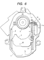
- a turn table 2 In a conventional CD player, as shown in Fig. 6, a turn table 2, a carriage 3, and the like are disposed on a chassis 1.
- the carriage 3 holds an objective lens 7 of a pickup in a center area thereof, and is placed in a center opening 1a of the chassis 1 so as to be movable in the anteroposterior direction (the direction along which the carriage approaches or separates from the turn table, and which corresponds to the vertical direction in the figure).
- Guide shafts 8 and 9 serving as guide members for guiding the carriage 3 in the anteroposterior direction are disposed on both sides (the left and right sides in the figure) of the movement space for the carriage in the center opening 1a of the chassis 1.
- One of the guide shafts, i.e., the guide shaft 8 is configured by a round bar.
- the other guide shaft 9 serves also as a screw shaft.
- the guide shaft 9 is rotated by a carriage drive motor 11 which is fixed onto the chassis 1 via a bracket 10.
- the guide shaft 9 and the output shaft 11a of the motor 11 are drivingly coupled to each other via a gear train configured by a driving gear 12, two intermediate gears 13, and a driven gear 14.
- the driving gear 12 is fixed to the output shaft 11a of the motor 11, the intermediate gears 13 are pivotally supported by a movable member which is not shown, and the driven gear 14 is fixed to the guide shaft 9.
- the carriage drive motor 11 is activated to repeatedly rotate the guide shaft 9 in forward and reverse, the carriage 3 reciprocates in the anteroposterior direction on the chassis 1 along the guide shafts 8 and 9, so that the objective lens 7 on the carriage 3 radially crosses a disk which is placed on the turn table 2, and which is not shown.
- the carriage drive motor 11 In order to ensure that the carriage 3 is quickly moved, the carriage drive motor 11 is rotated at a high speed of, for example, 12,000 rpm. This causes a problem in that the driving noise produced when the motor operates is bothersome.
- the exposed basal portion of the output shaft 11a is directly urged (laterally pressed) by an urging spring in a direction perpendicular to the axial direction of the shaft.
- this urging is conducted, the operation noise level in operation of the carriage drive motor 11 can be reduced by several decibels (db) as compared with the case where such urging is not conducted.
- an object of the invention to provide an urging structure for an output shaft of a drive motor which can prevent an excess load on an output shaft while reducing the driving noise level of a motor, thereby ensuring a starting voltage which is lower than that in a conventional motor.
- the urging structure for an output shaft of a drive motor is a structure which urges an output shaft of a drive motor in one direction to reduce a driving noise level when the drive motor operates, wherein urging means applies a force to an end face of the output shaft of the drive motor, in a direction oblique to an axial direction.
- an urging force (lateral pressure) is applied to the end face of the output shaft.
- urging in a radial direction of the output shaft can be conducted while reducing a load of friction braking on the output shaft. Consequently, the driving noise level of the motor can be reduced, and an excess load on the output shaft is prevented from occurring, so that an optimum control is enabled at a lower starting voltage.
- the urging structure for an output shaft of a drive motor is characterized in that the urging means has: a pressing plate in which a fulcrum is in the vicinity of the output shaft and a free end abuts against the end face of the output shaft; and an urging spring which urges the pressing plate in a direction oblique to the axial direction of the output shaft.
- the free end of the pressing plate is caused to abut against the end face of the output shaft by the urging force of the urging spring. Therefore, a sure contact with the end face of the output shaft can be ensured by the pressing plate, so that a stable abutting face can be assured.
- the urging spring is adequately selected, moreover, the load of a stable urging force can be provided.
- the urging structure for an output shaft of a drive motor is characterized in that the end face of the output shaft is formed into a spherical shape.
- the end face is formed into a spherical shape. Even when the pressing plate has a flat structure, therefore, a point contact is formed between the pressing plate and the portion of the output shaft against which the pressing plate abuts, and hence the contact resistance between the pressing plate and the rotated output shaft can be suppressed to a minimum level.
- the urging structure for an output shaft of a drive motor is characterized in that a cap in which a tip end has a spherical shape is fitted onto the end face of the output shaft to cover the end face.
- the cap in which the tip end has a spherical shape is fitted onto the end face to cover it, the length of the exposed portion of the output shaft can be shortened. Furthermore, it is not necessary to process the end face so as to have a spherical shape, and hence the number of processing steps can be reduced.
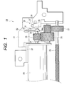
- Fig. 1 is a schematic plan view of a chassis peripheral portion of a CD player showing the urging structure for an output shaft of a drive motor according to the invention
- Fig. 2 is a partial enlarged view of main portions of Fig. 1
- Fig. 3 is a view looking in the direction of the arrow A in Fig. 2
- Fig. 4 is a side view showing a free end of a pressing plate in Fig. 2
- Fig. 5 is a partial enlarged view showing a modification of an end face of an output shaft in Fig. 1.
- a carriage drive motor 23 which is a high-speed (12,000 rpm) motor fixed onto a chassis 21 via a bracket 22 rotates a guide shaft 28 which serves also as a screw shaft.
- the guide shaft 28 and the output shaft 24 of the carriage drive motor 23 are drivingly coupled to each other via a gear train configured by a driving gear 25 fixed to the output shaft 24 of the carriage drive motor 23, two intermediate gears 26, and a driven gear 27 fixed to the guide shaft 28.
- a carriage which is not shown in the figure reciprocates in the anteroposterior direction (the direction along which the carriage approaches or separates from the turn table) on the chassis 21 along the guide shaft 28.
- the urging structure for an output shaft of a drive motor of the embodiment is configured so that the driving noise level when the motor operates is reduced by urging in one direction (laterally pressing) the output shaft 24 of the carriage drive motor 23, and comprises urging means 30 for applying a force to an end face 24a of the output shaft 24 of the carriage drive motor 23, in a direction oblique to the axial direction.
- the urging means 30 is configured by a pressing plate 31 which abuts against the end face 24a of the output shaft 24, and an urging spring 36 which urges the pressing plate in the axial direction of the output shaft 24.
- the pressing plate 31 is made of a polyacetal resin (POM) which has an excellent bending strength.
- a fixing portion 32 which serves as a fulcrum in one end is fixed onto the chassis 21 in the vicinity of the output shaft 24.
- An abutting portion 34 is disposed on the tip end of a flexible arm portion 33.
- a spring holding portion 35 with which an end portion of the urging spring 36 that is fixed to a spring boss 37 is to be engaged is disposed on the rear face of the abutting portion 34.
- the abutting portion 34 of the pressing plate 31 substantially perpendicularly abuts against the end face 24a of the output shaft 24 of the carriage drive motor 23.
- the abutting portion applies a load force F in an oblique direction of an acute angle ⁇ with respect to the axial direction of the output shaft 24 which is oriented to the motor.
- the pressing plate 31 can generate an urging force component F1 which urges the output shaft 24 in a radial direction of the shaft (in the upward direction in the figure) that is perpendicular to the axial direction, and an urging force component F2 which urges the output shaft 24 toward the motor in the axial direction.
- the output shaft 24 is urged by the urging force component F1 in the perpendicular direction and by the urging force component F2 in the axial direction, whereby stable rotation of the motor is attained, so that the driving noise level of the carriage drive motor 23 can be eliminated.
- the end face 24a of the output shaft 24 is formed into a spherical shape.
- the portion abutting against the pressing plate 31 constitutes as a point contact, and hence the contact resistance between the pressing plate and the rotated output shaft 24 can be suppressed to a minimum level.
- the contact 34a of the end face 24a of the output shaft 24 with which the pressing plate 31 is contacted functions as a position of the applied force F, and is not required to be on the center axis of the output shaft 24. As far as the contact is inside the radius of the output shaft 24, it is possible to obtain the urging force component F1.
- the urging force component F3 acts on the contact 34a of the end face 24a of the output shaft 24 with which the pressing plate 31 is contacted, and which is separated from the shaft center O by a length L
- the braking force acting in the rotation direction B of the output shaft 24 is F3 ⁇ L. Therefore, it will be seen that a braking force acts which is smaller than a braking force (F0 ⁇ L0) due to a force F0 that directly acts on the outer peripheral face of the output shaft 24 having a radius L0.
- a spring engagement groove 35a of a width which is slightly larger than the outer diameter of the urging spring 36 is disposed along the longitudinal direction of the arm portion 33, in the holding portion 35 on the rear face of the abutting portion 34 of the pressing plate 31. Therefore, an end portion of the urging spring 36 can be surely engaged with the spring engagement groove 35a, so that a stable urging force in one direction can be applied.
- the load force F can be applied by the urging spring 36 to the end face 24a of the output shaft 24 in the oblique direction of the angle ⁇ with respect to the axial direction.
- an appropriate load can be applied to the output shaft 24 by the urging force component F1 which is a component of the force F in a direction perpendicular to the output shaft 24 (a radial direction of the shaft), so that the output shaft 24 can be urged in a radial direction of the shaft while reducing a load of friction braking on the output shaft 24 as compared with the case where the output shaft is directly urged by a force oriented in a radial direction of the output shaft. Consequently, the driving noise level of the motor can be reduced by about 7 to 10 decibels (db) in comparison with the case where such urging is not conducted, and an optimum control is enabled at a lower starting voltage.
- db decibels
- the abutting portion 34 which is the free end of the pressing plate is caused to abut against the end face 24a of the output shaft 24 from the rear face side of the pressing plate 31 by the urging force F of the urging spring 36. Therefore, a sure contact with the end face 24a of the output shaft 24 can be ensured by the pressing plate 31, so that a stable abutting face can be assured.
- the urging spring 36 is adequately selected, the load of a stable urging force can be provided.
- the end face 24a of the output shaft 24 is formed into a spherical shape and completely exposed.
- the end face may not be exposed and may be covered by a cap 25a which has a spherical tip end, and which is molded integrally with or separately from the driving gear 25.
- the pressing plate 31 may abut against the cap 25a.
- the embodiment in which the invention is applied to a carriage drive motor has been exemplarily described.
- the invention may be applied also to a motor of another kind such as a turntable motor.
- a force is applied to the end face of the output shaft of the drive motor in a direction oblique to the axial direction, and hence an urging force component which urges the output shaft in one direction can be obtained.
Landscapes
- Engineering & Computer Science (AREA)
- Power Engineering (AREA)
- General Engineering & Computer Science (AREA)
- Mechanical Engineering (AREA)
- Motor Or Generator Frames (AREA)
- Connection Of Motors, Electrical Generators, Mechanical Devices, And The Like (AREA)
- Character Spaces And Line Spaces In Printers (AREA)
- Transmission Devices (AREA)
- Gear Transmission (AREA)
- Moving Of Heads (AREA)
Abstract
Description
- The present invention relates to an urging structure for an output shaft of a drive motor, and more particularly to an urging structure for an output shaft of a small drive motor such as a carriage motor which is used for driving a pickup of a CD player.
- In a conventional CD player, as shown in Fig. 6, a turn table 2, a
carriage 3, and the like are disposed on achassis 1. Thecarriage 3 holds anobjective lens 7 of a pickup in a center area thereof, and is placed in acenter opening 1a of thechassis 1 so as to be movable in the anteroposterior direction (the direction along which the carriage approaches or separates from the turn table, and which corresponds to the vertical direction in the figure). -
Guide shafts carriage 3 in the anteroposterior direction are disposed on both sides (the left and right sides in the figure) of the movement space for the carriage in thecenter opening 1a of thechassis 1. One of the guide shafts, i.e., theguide shaft 8 is configured by a round bar. Theother guide shaft 9 serves also as a screw shaft. - The
guide shaft 9 is rotated by acarriage drive motor 11 which is fixed onto thechassis 1 via abracket 10. Theguide shaft 9 and theoutput shaft 11a of themotor 11 are drivingly coupled to each other via a gear train configured by adriving gear 12, twointermediate gears 13, and a drivengear 14. - The
driving gear 12 is fixed to theoutput shaft 11a of themotor 11, theintermediate gears 13 are pivotally supported by a movable member which is not shown, and the drivengear 14 is fixed to theguide shaft 9. When thecarriage drive motor 11 is activated to repeatedly rotate theguide shaft 9 in forward and reverse, thecarriage 3 reciprocates in the anteroposterior direction on thechassis 1 along theguide shafts objective lens 7 on thecarriage 3 radially crosses a disk which is placed on the turn table 2, and which is not shown. - In order to ensure that the
carriage 3 is quickly moved, thecarriage drive motor 11 is rotated at a high speed of, for example, 12,000 rpm. This causes a problem in that the driving noise produced when the motor operates is bothersome. In order to reduce the driving noise level, the exposed basal portion of theoutput shaft 11a is directly urged (laterally pressed) by an urging spring in a direction perpendicular to the axial direction of the shaft. When this urging is conducted, the operation noise level in operation of thecarriage drive motor 11 can be reduced by several decibels (db) as compared with the case where such urging is not conducted. - Since the exposed basal portion of the output shaft is directly urged by the urging spring, the urging force is large, and hence the load on the output shaft is increased so that the starting voltage is required to be high. This causes a problem in that the carriage cannot be finely motor-controlled at a low voltage.
- In order to solve the problem, it is an object of the invention to provide an urging structure for an output shaft of a drive motor which can prevent an excess load on an output shaft while reducing the driving noise level of a motor, thereby ensuring a starting voltage which is lower than that in a conventional motor.
- In order to attain the object, the urging structure for an output shaft of a drive motor according to the invention is a structure which urges an output shaft of a drive motor in one direction to reduce a driving noise level when the drive motor operates, wherein urging means applies a force to an end face of the output shaft of the drive motor, in a direction oblique to an axial direction.
- In the thus configured urging structure for an output shaft of a drive motor, since a force is applied to the end face of the output shaft of the drive motor in a direction oblique to the axial direction, an urging force component which urges the output shaft in a radial direction of the shaft can be obtained, and also another urging force component which urges the output shaft in the axial direction can be obtained.
- Therefore, an urging force (lateral pressure) is applied to the end face of the output shaft. As compared with the case where the output shaft is directly urged by a force oriented in a radial direction of the output shaft, urging in a radial direction of the output shaft can be conducted while reducing a load of friction braking on the output shaft. Consequently, the driving noise level of the motor can be reduced, and an excess load on the output shaft is prevented from occurring, so that an optimum control is enabled at a lower starting voltage.
- Moreover, the urging structure for an output shaft of a drive motor is characterized in that the urging means has: a pressing plate in which a fulcrum is in the vicinity of the output shaft and a free end abuts against the end face of the output shaft; and an urging spring which urges the pressing plate in a direction oblique to the axial direction of the output shaft.
- In the thus configured urging structure for an output shaft of a drive motor, the free end of the pressing plate is caused to abut against the end face of the output shaft by the urging force of the urging spring. Therefore, a sure contact with the end face of the output shaft can be ensured by the pressing plate, so that a stable abutting face can be assured. When the urging spring is adequately selected, moreover, the load of a stable urging force can be provided.
- Moreover, the urging structure for an output shaft of a drive motor is characterized in that the end face of the output shaft is formed into a spherical shape.
- In the thus configured urging structure for an output shaft of a drive motor, the end face is formed into a spherical shape. Even when the pressing plate has a flat structure, therefore, a point contact is formed between the pressing plate and the portion of the output shaft against which the pressing plate abuts, and hence the contact resistance between the pressing plate and the rotated output shaft can be suppressed to a minimum level.
- Moreover, the urging structure for an output shaft of a drive motor is characterized in that a cap in which a tip end has a spherical shape is fitted onto the end face of the output shaft to cover the end face.
- In the thus configured urging structure for an output shaft of a drive motor, since the cap in which the tip end has a spherical shape is fitted onto the end face to cover it, the length of the exposed portion of the output shaft can be shortened. Furthermore, it is not necessary to process the end face so as to have a spherical shape, and hence the number of processing steps can be reduced.
-
- Fig. 1 is a schematic plan view of a chassis peripheral portion of a CD player showing the urging structure for an output shaft of a drive motor according to the invention;
- Fig. 2 is a partial enlarged view of main portions of Fig. 1;
- Fig. 3 is a view looking in the direction of the arrow A in Fig. 2;
- Fig. 4 is a side view showing a free end of a pressing plate in Fig. 2;
- Fig. 5 is a partial enlarged view showing a modification of an end face of an output shaft in Fig. 1; and
- Fig. 6 is a plan view of a chassis peripheral portion of a CD player of a conventional CD player.
-
- Hereinafter, an embodiment of the urging structure for an output shaft of a drive motor according to the invention will be described in detail with reference to Figs. 1 to 5.
- Fig. 1 is a schematic plan view of a chassis peripheral portion of a CD player showing the urging structure for an output shaft of a drive motor according to the invention, Fig. 2 is a partial enlarged view of main portions of Fig. 1, Fig. 3 is a view looking in the direction of the arrow A in Fig. 2, Fig. 4 is a side view showing a free end of a pressing plate in Fig. 2, and Fig. 5 is a partial enlarged view showing a modification of an end face of an output shaft in Fig. 1.
- Detailed description of components which are identical with those of the conventional art will be omitted.
- As shown in Fig. 1, in a chassis
peripheral portion 20 of a CD player showing the urging structure for an output shaft of a drive motor of the embodiment, acarriage drive motor 23 which is a high-speed (12,000 rpm) motor fixed onto achassis 21 via abracket 22 rotates aguide shaft 28 which serves also as a screw shaft. - The
guide shaft 28 and theoutput shaft 24 of thecarriage drive motor 23 are drivingly coupled to each other via a gear train configured by adriving gear 25 fixed to theoutput shaft 24 of thecarriage drive motor 23, twointermediate gears 26, and a drivengear 27 fixed to theguide shaft 28. - When the
carriage drive motor 23 is activated to repeatedly rotate theguide shaft 28 in forward and reverse, a carriage (see Fig. 6) which is not shown in the figure reciprocates in the anteroposterior direction (the direction along which the carriage approaches or separates from the turn table) on thechassis 21 along theguide shaft 28. - The urging structure for an output shaft of a drive motor of the embodiment is configured so that the driving noise level when the motor operates is reduced by urging in one direction (laterally pressing) the
output shaft 24 of thecarriage drive motor 23, and comprisesurging means 30 for applying a force to anend face 24a of theoutput shaft 24 of thecarriage drive motor 23, in a direction oblique to the axial direction. - The
urging means 30 is configured by apressing plate 31 which abuts against theend face 24a of theoutput shaft 24, and anurging spring 36 which urges the pressing plate in the axial direction of theoutput shaft 24. - The
pressing plate 31 is made of a polyacetal resin (POM) which has an excellent bending strength. Afixing portion 32 which serves as a fulcrum in one end is fixed onto thechassis 21 in the vicinity of theoutput shaft 24. An abuttingportion 34 is disposed on the tip end of aflexible arm portion 33. - A
spring holding portion 35 with which an end portion of theurging spring 36 that is fixed to aspring boss 37 is to be engaged is disposed on the rear face of the abuttingportion 34. - As shown in Fig. 2, the
abutting portion 34 of thepressing plate 31 substantially perpendicularly abuts against theend face 24a of theoutput shaft 24 of thecarriage drive motor 23. By means of the urging force of theurging spring 36 which is engaged with thespring holding portion 35 on the rear face of the abuttingportion 34, the abutting portion applies a load force F in an oblique direction of an acute angle with respect to the axial direction of theoutput shaft 24 which is oriented to the motor. As a result, thepressing plate 31 can generate an urging force component F1 which urges theoutput shaft 24 in a radial direction of the shaft (in the upward direction in the figure) that is perpendicular to the axial direction, and an urging force component F2 which urges theoutput shaft 24 toward the motor in the axial direction. - Therefore, the
output shaft 24 is urged by the urging force component F1 in the perpendicular direction and by the urging force component F2 in the axial direction, whereby stable rotation of the motor is attained, so that the driving noise level of thecarriage drive motor 23 can be eliminated. - The
end face 24a of theoutput shaft 24 is formed into a spherical shape. - According to the configuration, the portion abutting against the
pressing plate 31 constitutes as a point contact, and hence the contact resistance between the pressing plate and therotated output shaft 24 can be suppressed to a minimum level. - The
contact 34a of theend face 24a of theoutput shaft 24 with which thepressing plate 31 is contacted functions as a position of the applied force F, and is not required to be on the center axis of theoutput shaft 24. As far as the contact is inside the radius of theoutput shaft 24, it is possible to obtain the urging force component F1. - Specifically, in the case where, as shown in Fig. 3, the urging force component F3 acts on the
contact 34a of theend face 24a of theoutput shaft 24 with which thepressing plate 31 is contacted, and which is separated from the shaft center O by a length L, the braking force acting in the rotation direction B of theoutput shaft 24 is F3 × L. Therefore, it will be seen that a braking force acts which is smaller than a braking force (F0 × L0) due to a force F0 that directly acts on the outer peripheral face of theoutput shaft 24 having a radius L0. - As shown in Fig. 4, a
spring engagement groove 35a of a width which is slightly larger than the outer diameter of theurging spring 36 is disposed along the longitudinal direction of thearm portion 33, in theholding portion 35 on the rear face of theabutting portion 34 of thepressing plate 31. Therefore, an end portion of theurging spring 36 can be surely engaged with thespring engagement groove 35a, so that a stable urging force in one direction can be applied. - According to the urging structure for an output shaft of a drive motor of the embodiment, the load force F can be applied by the
urging spring 36 to theend face 24a of theoutput shaft 24 in the oblique direction of the angle with respect to the axial direction. - Therefore, an appropriate load can be applied to the
output shaft 24 by the urging force component F1 which is a component of the force F in a direction perpendicular to the output shaft 24 (a radial direction of the shaft), so that theoutput shaft 24 can be urged in a radial direction of the shaft while reducing a load of friction braking on theoutput shaft 24 as compared with the case where the output shaft is directly urged by a force oriented in a radial direction of the output shaft. Consequently, the driving noise level of the motor can be reduced by about 7 to 10 decibels (db) in comparison with the case where such urging is not conducted, and an optimum control is enabled at a lower starting voltage. - The abutting
portion 34 which is the free end of the pressing plate is caused to abut against theend face 24a of theoutput shaft 24 from the rear face side of thepressing plate 31 by the urging force F of the urgingspring 36. Therefore, a sure contact with theend face 24a of theoutput shaft 24 can be ensured by thepressing plate 31, so that a stable abutting face can be assured. When the urgingspring 36 is adequately selected, the load of a stable urging force can be provided. - In the embodiment described above, the
end face 24a of theoutput shaft 24 is formed into a spherical shape and completely exposed. Alternatively, as shown in Fig. 5, the end face may not be exposed and may be covered by acap 25a which has a spherical tip end, and which is molded integrally with or separately from thedriving gear 25. Thepressing plate 31 may abut against thecap 25a. - In the alternative, it is not necessary to process the
end face 24a so as to have a spherical shape. When thecap 25a is made of the same material as thepressing plate 31, wear of the abutting faces of the two members due to the rotation of thedriving gear 25 can be reduced. - In the above, the embodiment in which the invention is applied to a carriage drive motor has been exemplarily described. The invention may be applied also to a motor of another kind such as a turntable motor.
- As described above, according to the urging structure for an output shaft of a drive motor of the invention, a force is applied to the end face of the output shaft of the drive motor in a direction oblique to the axial direction, and hence an urging force component which urges the output shaft in one direction can be obtained.
- Therefore, an urging force is applied to the end face of the output shaft. As compared with the case where the output shaft is directly urged in one direction, predetermined load can be applied to the output shaft by a small urging force. Consequently, the driving noise level of the motor can be reduced, and an excess load on the output shaft is prevented from occurring, so that an optimum starting voltage is ensured.
- In the urging structure for an output shaft of a drive motor, since the free end of the pressing plate is caused to abut against the end face of the output shaft by the urging force of the urging spring, a stable abutting face can be ensured, and the load of a stable urging force can be provided in a predetermined direction from the rear face side of the pressing plate.
- In the urging structure for an output shaft of a drive motor, since the end face of the output shaft is formed into a spherical shape, a point contact is formed between the pressing plate and the end face, and hence the contact resistance between the pressing plate and the rotated output shaft can be suppressed to a minimum level.
Claims (4)
- An urging structure for an output shaft of a drive motor which urges an output shaft of a drive motor in one direction to reduce a driving noise level when said drive motor operates, said structure comprising:an urging unit adapted to apply a force to an end face of said output shaft of said drive motor, in a direction oblique to an axial direction.
- The urging structure for an output shaft of a drive motor according to claim 1, wherein said urging unit has: a pressing plate in which a fulcrum is in the vicinity of said output shaft and a free end abuts against said end face of said output shaft; and an urging spring which urges said pressing plate in a direction oblique to the axial direction o said output shaft.
- The urging structure for an output shaft of a drive motor according to claim 1, wherein said end face of said output shaft is formed into a spherical shape.
- The urging structure for an output shaft of a drive motor according to claim 1, further comprising a cap having a spherical tip end thereof and being fitted onto said end face of said output shaft to cover said end face.
Applications Claiming Priority (2)
| Application Number | Priority Date | Filing Date | Title |
|---|---|---|---|
| JP2001181742 | 2001-06-15 | ||
| JP2001181742A JP2003009460A (en) | 2001-06-15 | 2001-06-15 | Thrusting structure of output shaft of driving motor |
Publications (2)
| Publication Number | Publication Date |
|---|---|
| EP1271492A1 true EP1271492A1 (en) | 2003-01-02 |
| EP1271492B1 EP1271492B1 (en) | 2005-07-13 |
Family
ID=19021965
Family Applications (1)
| Application Number | Title | Priority Date | Filing Date |
|---|---|---|---|
| EP02253709A Expired - Lifetime EP1271492B1 (en) | 2001-06-15 | 2002-05-27 | Urging structure for an output shaft of a drive motor |
Country Status (4)
| Country | Link |
|---|---|
| US (1) | US7003787B2 (en) |
| EP (1) | EP1271492B1 (en) |
| JP (1) | JP2003009460A (en) |
| DE (1) | DE60204996T2 (en) |
Families Citing this family (1)
| Publication number | Priority date | Publication date | Assignee | Title |
|---|---|---|---|---|
| KR100524073B1 (en) * | 2003-08-04 | 2005-10-26 | 삼성전자주식회사 | Structure for adjusting lead screw of disc drive |
Citations (8)
| Publication number | Priority date | Publication date | Assignee | Title |
|---|---|---|---|---|
| US3848477A (en) * | 1972-03-15 | 1974-11-19 | Magneti Marelli Spa | Device for guiding and resuming the axial clearance in screws of reduction worms, particularly for low power geared motor |
| DE2714332A1 (en) * | 1977-03-31 | 1978-10-05 | Papst Motoren Kg | Reduction of axial play in cassette player drive - uses spring clamp bearing with small radial thrust |
| DE2809390A1 (en) * | 1978-03-04 | 1979-09-06 | Rau Swf Autozubehoer | ELECTRIC DRIVE UNIT, IN PARTICULAR FOR WIPER MOTOR |
| GB2147728A (en) * | 1983-10-07 | 1985-05-15 | Alps Electric Co Ltd | Magnetic head feed mechanism |
| JPH06133490A (en) * | 1992-10-15 | 1994-05-13 | Sony Corp | Thrust preload spring |
| US5886438A (en) * | 1996-01-08 | 1999-03-23 | Canon Kabushiki Kaisha | Stepping motor having bobbin structure materially integrally formed with a bearing and a positioning portion |
| EP1035632A1 (en) * | 1998-09-29 | 2000-09-13 | Mitsubishi Denki Kabushiki Kaisha | Motor supporting device |
| EP1041698A2 (en) * | 1999-03-30 | 2000-10-04 | Canon Kabushiki Kaisha | Motor |
Family Cites Families (7)
| Publication number | Priority date | Publication date | Assignee | Title |
|---|---|---|---|---|
| US4030137A (en) * | 1975-09-23 | 1977-06-14 | Shugart Associates, Inc. | Lead screw support damping mechanism |
| IT1162944B (en) * | 1983-09-29 | 1987-04-01 | Olivetti & Co Spa | MACHINE OF INTERLINEA FOR WRITING MACHINE |
| JPH0417865Y2 (en) * | 1986-12-15 | 1992-04-21 | ||
| US5811903A (en) * | 1995-09-26 | 1998-09-22 | Sankyo Seiki Mfg. Co., Ltd. | Motor |
| US6052358A (en) * | 1996-10-04 | 2000-04-18 | Sony Corporation | Head feeding mechanism and optical pick-up feeding mechanism |
| KR100318827B1 (en) * | 1999-03-17 | 2002-01-04 | 이형도 | A stepping motor |
| JP2000285560A (en) * | 1999-03-31 | 2000-10-13 | Hitachi Ltd | Disk drive |
-
2001
- 2001-06-15 JP JP2001181742A patent/JP2003009460A/en active Pending
-
2002
- 2002-05-27 DE DE60204996T patent/DE60204996T2/en not_active Expired - Fee Related
- 2002-05-27 EP EP02253709A patent/EP1271492B1/en not_active Expired - Lifetime
- 2002-06-11 US US10/165,977 patent/US7003787B2/en not_active Expired - Fee Related
Patent Citations (8)
| Publication number | Priority date | Publication date | Assignee | Title |
|---|---|---|---|---|
| US3848477A (en) * | 1972-03-15 | 1974-11-19 | Magneti Marelli Spa | Device for guiding and resuming the axial clearance in screws of reduction worms, particularly for low power geared motor |
| DE2714332A1 (en) * | 1977-03-31 | 1978-10-05 | Papst Motoren Kg | Reduction of axial play in cassette player drive - uses spring clamp bearing with small radial thrust |
| DE2809390A1 (en) * | 1978-03-04 | 1979-09-06 | Rau Swf Autozubehoer | ELECTRIC DRIVE UNIT, IN PARTICULAR FOR WIPER MOTOR |
| GB2147728A (en) * | 1983-10-07 | 1985-05-15 | Alps Electric Co Ltd | Magnetic head feed mechanism |
| JPH06133490A (en) * | 1992-10-15 | 1994-05-13 | Sony Corp | Thrust preload spring |
| US5886438A (en) * | 1996-01-08 | 1999-03-23 | Canon Kabushiki Kaisha | Stepping motor having bobbin structure materially integrally formed with a bearing and a positioning portion |
| EP1035632A1 (en) * | 1998-09-29 | 2000-09-13 | Mitsubishi Denki Kabushiki Kaisha | Motor supporting device |
| EP1041698A2 (en) * | 1999-03-30 | 2000-10-04 | Canon Kabushiki Kaisha | Motor |
Non-Patent Citations (1)
| Title |
|---|
| PATENT ABSTRACTS OF JAPAN vol. 018, no. 434 (E - 1592) 12 August 1994 (1994-08-12) * |
Also Published As
| Publication number | Publication date |
|---|---|
| DE60204996T2 (en) | 2005-12-29 |
| US20020191529A1 (en) | 2002-12-19 |
| DE60204996D1 (en) | 2005-08-18 |
| JP2003009460A (en) | 2003-01-10 |
| US7003787B2 (en) | 2006-02-21 |
| EP1271492B1 (en) | 2005-07-13 |
Similar Documents
| Publication | Publication Date | Title |
|---|---|---|
| US6058098A (en) | Head driving device | |
| JP2001110152A (en) | Transfer mechanism for light pickup | |
| EP0990782B1 (en) | Accelerator pedal mechanism for vehicle | |
| US6918129B2 (en) | Disc drive head driver | |
| EP1271492B1 (en) | Urging structure for an output shaft of a drive motor | |
| US6657943B2 (en) | Pickup feed mechanism | |
| JP2001273732A (en) | Optical pickup transfer mechanism | |
| US5546252A (en) | Thin and small-sized flexible disc unit | |
| JP3359527B2 (en) | Head feeder | |
| JP4059720B2 (en) | Pickup transfer device | |
| EP0964396B1 (en) | Disk supporting device | |
| US7334239B2 (en) | Optical disc apparatus | |
| JP3245543B2 (en) | Disk unit | |
| JPH10144017A (en) | Bearing structure for stepping motor | |
| JP2638071B2 (en) | Head moving device | |
| JPH11306700A (en) | Head feeding device | |
| JP3005823U (en) | Magnetic recording device | |
| JP3839936B2 (en) | Optical pickup holding mechanism | |
| JP2501848Y2 (en) | Pickup feeder | |
| KR100432498B1 (en) | Spring for motor and optical disk driver having thereof | |
| JP2000251422A (en) | Optical pickup feed mechanism | |
| JPH1145487A (en) | Optical disk drive | |
| JP3286547B2 (en) | Optical pickup feeder | |
| JP4045238B2 (en) | Optical pickup feeder | |
| JP2568097Y2 (en) | Disc player spring nut |
Legal Events
| Date | Code | Title | Description |
|---|---|---|---|
| PUAI | Public reference made under article 153(3) epc to a published international application that has entered the european phase |
Free format text: ORIGINAL CODE: 0009012 |
|
| AK | Designated contracting states |
Kind code of ref document: A1 Designated state(s): AT BE CH CY DE DK ES FI FR GB GR IE IT LI LU MC NL PT SE TR |
|
| AX | Request for extension of the european patent |
Free format text: AL;LT;LV;MK;RO;SI |
|
| 17P | Request for examination filed |
Effective date: 20030617 |
|
| 17Q | First examination report despatched |
Effective date: 20030804 |
|
| AKX | Designation fees paid |
Designated state(s): DE FR GB |
|
| GRAP | Despatch of communication of intention to grant a patent |
Free format text: ORIGINAL CODE: EPIDOSNIGR1 |
|
| GRAS | Grant fee paid |
Free format text: ORIGINAL CODE: EPIDOSNIGR3 |
|
| GRAA | (expected) grant |
Free format text: ORIGINAL CODE: 0009210 |
|
| AK | Designated contracting states |
Kind code of ref document: B1 Designated state(s): DE FR GB |
|
| REG | Reference to a national code |
Ref country code: GB Ref legal event code: FG4D |
|
| REF | Corresponds to: |
Ref document number: 60204996 Country of ref document: DE Date of ref document: 20050818 Kind code of ref document: P |
|
| ET | Fr: translation filed | ||
| PLBE | No opposition filed within time limit |
Free format text: ORIGINAL CODE: 0009261 |
|
| STAA | Information on the status of an ep patent application or granted ep patent |
Free format text: STATUS: NO OPPOSITION FILED WITHIN TIME LIMIT |
|
| 26N | No opposition filed |
Effective date: 20060418 |
|
| PGFP | Annual fee paid to national office [announced via postgrant information from national office to epo] |
Ref country code: DE Payment date: 20090527 Year of fee payment: 8 Ref country code: FR Payment date: 20090515 Year of fee payment: 8 |
|
| PGFP | Annual fee paid to national office [announced via postgrant information from national office to epo] |
Ref country code: GB Payment date: 20090527 Year of fee payment: 8 |
|
| GBPC | Gb: european patent ceased through non-payment of renewal fee |
Effective date: 20100527 |
|
| REG | Reference to a national code |
Ref country code: FR Ref legal event code: ST Effective date: 20110131 |
|
| PG25 | Lapsed in a contracting state [announced via postgrant information from national office to epo] |
Ref country code: DE Free format text: LAPSE BECAUSE OF NON-PAYMENT OF DUE FEES Effective date: 20101201 |
|
| PG25 | Lapsed in a contracting state [announced via postgrant information from national office to epo] |
Ref country code: FR Free format text: LAPSE BECAUSE OF NON-PAYMENT OF DUE FEES Effective date: 20100531 |
|
| PG25 | Lapsed in a contracting state [announced via postgrant information from national office to epo] |
Ref country code: GB Free format text: LAPSE BECAUSE OF NON-PAYMENT OF DUE FEES Effective date: 20100527 |