BACKGROUND OF THE INVENTION
FIELD OF THE INVENTION
This invention relates to an information terminal which is
capable of being installed with functions distributed for
carrying.
The present application claims priority from Japanese
Application No. 2001-189912, the disclosure of which is
incorporated herein by reference for all purposes.
DESCRIPTION OF THE RELATED ART
In recent years, various types of portable information
terminals such as a notebook-type personal computer, a PDA, a
portable telephone and the like have become rapidly and widely
available. Along with this, a variety of functions installed on
portable information terminals for information processing have
become rapidly enhanced.
However, with the explosive progression of information
technology, a disparity between persons in the degree of successful
usage of the information terminals has widened, which has raised
the serious problem associated with the so-called "digital divide"
in which persons unskilled in handling the information terminals
are falling behind in society in terms of jobs, income and the
like.
In the future, with the diversification of the needs of
society, a portable information terminal alone must be
increasingly required to meet the miscellaneous needs, e.g.,
communication, transmission and collection of information,
accumulation and editing of information, electronic commerce, and
controls for other devices. For this requirement, a multifunction
design for portable information terminals will need to be further
progressed to increase the number of available functions, and in
consequence the manipulation thereof will be further complicated,
which must make the problem of the "digital divide" even more
significantly serious.
In addition, such progress in multifunction design will
enable a single portable information terminal to accumulate
various kinds of information including personal information,
which produces another serious problem of how to ensure security
when a high volume of information accumulated is carried around.
SUMMARY OF THE INVENTION
The present invention has been made to solve the problems
associated with progress in multifunction design to increase the
number of available functions in portable information terminals
as described above.
It is therefore an object of the present invention to provide
a portable information terminal capable of solving the problem
of the "digital divide" deepening with the progress in
multifunction design, and of enhancing security when a high volume
of information accumulated is carried around.
To attain the above object, according to a first feature of
the present invention, there is provided a portable information
terminal comprising a primary terminal and a secondary terminal
which are separably combined with each other. The primary and
secondary terminals each have a display, a manipulation element,
a memory section for storing application programs, a communication
element, and a control section for controlling the display,
manipulation element, memory section and communication element.
The control section of each of the primary and secondary terminals
independently performs a control operation under an activated
application program stored in the memory section thereof to operate
a required function and allow the display to display an image in
accordance with the manipulation of the manipulation element
thereof. Through communication between the communication
elements of the primary terminal and the secondary terminal, the
control sections of the primary and secondary terminals are
connected to each other for a systematic link between the
respective manipulation elements in terms of manipulation, to
perform a linked operation for a required function and allow the
respective displays to display mutually associated images in
accordance with the manipulation of the respective manipulation
elements under the application program stored in one or both of
the memory sections of the primary and secondary terminals.
In the first feature, the portable information terminal
comprises the primary and secondary terminals each of which is
capable of independently executing a required function, and also
which are capable of executing a required function in coordination
with each other when they are combined.
Specifically, the primary terminal and the secondary terminal
each include the display for displaying a video image or an image
for data processing, the control section for operating the display
to display an image or the like and performing the operation
necessary for data processing, the manipulation element for
inputting manipulation into the control section, and the memory
section for storing application programs for executing a variety
of functions and various kinds of data. In each of the primary
and secondary terminals when they are separated from each other,
the control section performs the operational control in accordance
with the manipulation inputted in the manipulation element to
activate the application program stored in the memory section,
and thus the primary or secondary terminal can execute the
necessary functions independently.
The primary and secondary terminals each include the
communication element capable of performing data communication
between the primary and secondary terminals. Therefore, in either
case, when the primary and secondary terminals are combined or
separated, the data communication between both communication
elements allows both the control sections to connect to each other
for a systematic link. The systematic link between the control
sections allows a systematic link between both of the manipulation
elements.
In the situation when the control sections of the primary
and secondary terminals are connected through the respective
communication elements, when the application program stored in
one or both of the memory sections is activated, the linked primary
and secondary terminals perform the required function operation
in accordance with the linked manipulation input of both the
manipulation elements. Further, for example, in the case of the
combination of the main and secondary terminals, the displays of
the main and secondary terminals form a double window, which allows
one of the displays to be used as a main display screen and the
other to be used as an auxiliary display screen for displaying
an icon bar, a toolbar and the like. With such a usage pattern,
the main and secondary terminals can fully perform all of their
functions.
In the case of the first feature, therefore, the primary and
secondary terminals which can either be combined or separated from
each other each have the ability to execute functions independently.
Hence, each of the primary terminal and the secondary terminal
can be assigned independently executable functions, so that it
is possible to simplify the manipulation for executing each of
the functions, resulting in avoidance of the "digital divide"
problem associated with the progress in multifunction design for
information terminals.
Further, the portable information terminal of the present
invention is designed to establish communication between the
primary and secondary terminals to allow the primary and secondary
terminals to be systematically linked for execution of a single
function as required. With this design, the portable information
terminal can fully function as a mobile computer.
Still further, in the portable information terminal, various
kinds of data can be distributed for storage in the primary and
secondary terminals. Hence, the degree of risk when the
information terminal is carried around is decreased, resulting
in the enhancement of security on data stored in the portable
information terminal.
To attain the aforementioned object, according to a second
feature of the present invention, in addition to the configuration
of the first feature, the primary terminal further includes a
secondary-terminal mounting base for attaching the secondary
terminal for combination, and a combination detection member
provided, in the secondary-terminal mounting base, for detecting
attachment of the secondary terminal and then connecting the
control section of the primary terminal to the control section
of the secondary terminal.
With the portable information terminal according to the
second feature, the secondary terminal is attached to the
secondary-terminal mounting base provided in the primary terminal
for combination with the primary terminal. When this takes place,
the attachment of the secondary terminal to the primary terminal
is detected by the combination detection member installed in the
mounting base, and then the control section of the primary terminal
is automatically connected systematically to the control section
of the secondary terminal.
To attain the aforementioned object, according to a third
feature of the invention, in addition to the configuration of the
first feature, the primary terminal further includes an interface
for mounting an external storage medium.
With the portable information terminal according to the third
feature, for example, if an external storage medium such as a memory
card or the like storing a variety of application programs is loaded
in the interface as required, it becomes possible to selectively
set or add a required function or change the functions. If video
software is loaded, the user can enjoy watching a film. Further,
with the addition of a memory card, a storage capacity for
accumulating data can be easily increased, for example.
To attain the aforementioned object, according to a fourth
feature of the invention, in addition to the configuration of the
third feature, the interface of the primary terminal of the primary
terminal is a DVD drive.
With the portable information terminal according to the
fourth feature, if video software is loaded in the DVD drive, the
primary terminal can serve as a DVD player. If a DVD storage medium
storing various application programs, data or the like is loaded
in the DVD drive, then it becomes possible to set or add a required
function, change functions, increase a storage capacity, or the
like.
To attain the aforementioned object, according to a fifth
feature of the invention, in addition to the configuration of the
third feature, the interface of the primary terminal is a
memory-card interface.
With the portable information terminal according to the fifth
feature, when the memory-card interface is loaded with a memory
card such as a Smartmedia, compact flash, memory stick, multimedia
card or the like, it is very easy to set or add a required function
or change functions of the primary terminal or increase the storage
capacity, for example.
To attain the aforementioned object, according to a sixth
feature of the invention, in addition to the configuration of the
first feature, the display of the primary terminal has a display
screen area larger than that of the display of the secondary
terminal.
With the portable information terminal according to the sixth
feature, for example, if the secondary terminal is designed
according to portable telephone specifications, and has a
relatively small sized display, various kinds of data stored in
the secondary terminal can be edited on the larger display of the
primary terminal. Further, thanks to the larger display of the
primary terminal, the secondary terminal can fully function as
a mobile computer.
To attain the aforementioned object, according to a seventh
feature of the invention, in addition to the configuration of the
first feature, the communication element of the primary terminal
performs Bluetooth communication to communicate with the
communication element of the secondary terminal.
With the portable information terminal of the seventh feature,
since the communication between the primary and secondary
terminals is based on the Bluetooth technology, it is possible
to enhance security by means of authentication and encryption
processing which are required in the Bluetooth technology.
To attain the aforementioned object, according to an eighth
feature of the invention, in addition to the configuration of the
first feature, the secondary terminal further includes an
interface for mounting an external storage medium.
With the portable information terminal of the eighth feature,
for example, if an external storage medium such as a memory card
storing a variety of application programs is loaded in the
interface as required, it becomes possible to selectively set or
add a required function or change functions. Further, with the
addition of a memory card, a storage capacity for accumulating
data can be easily increased, for example.
To attain the aforementioned object, according to a ninth
feature of the invention, in addition to the configuration of the
eighth feature, the interface of the secondary terminal is a
memory-card interface.
With the portable information terminal of the ninth feature,
when the memory-card interface is loaded with a memory card such
as a SmartMedia, compact flash, memory stick or multimedia card,
it is very easy to set or add a required function or change functions
of the primary terminal and increase the storage capacity, for
example.
To attain the aforementioned object, according to a tenth
feature of the invention, in addition to the configuration of the
first feature, the secondary terminal further includes a digital
photographing member.
With the portable information terminal of the tenth feature,
the secondary terminal can be used as a digital camera by operating
the digital photographing member. Further, with the combination
of the secondary terminal with the primary terminal, the display
of the primary terminal can show an image photographed by the
digital photographing member, to provide for simplified editing
of the image.
To attain the aforementioned object, according to an eleventh
feature of the invention, in addition to the configuration of the
first feature, the manipulation element of the secondary terminal
includes a key-button member, a jog dial member and a joystick
member.
With the portable information terminal of the eleventh
feature, the secondary terminal is operated through manipulation
of the key-button member, jog dial member and joystick member which
form the manipulation element. And also, when the secondary
terminal is combined with the primary terminal, the manipulation
members can be systematically linked to the manipulation element
of the primary terminal in terms of the manipulation input. This
design allow the portable information terminal to fully function
as a mobile computer.
To attain the aforementioned object, according to a twelfth
feature of the invention, in addition to the configuration of the
first feature, the display of the secondary terminal is fitted
movably in relation to a portion of the secondary terminal attached
to the primary terminal, to be set in a position selected from
a plurality of selectable positional patterns with respect to the
display of the primary terminal when the secondary terminal is
combined with the primary terminal.
With the portable information terminal of the twelfth feature,
when the display of the secondary terminal is moved in relation
to the portion in which the manipulation element of the secondary
terminal is located, and the secondary terminal is combined with
the primary terminal, the display of the secondary terminal is
set in a desired position with respect to the display of the primary
terminal. For example, the display of the secondary terminal is
placed in parallel with and along a top edge of the display of
the primary terminal. Such selecting of the positioning further
improves the effect of image display in the double window
constructed by the displays of the secondary and primary terminals.
To attain the aforementioned object, according to a
thirteenth feature of the invention, in addition to the
configuration of the twelfth feature, the secondary terminal
further includes a positional detection member for detecting
positions of the display of the secondary terminal, and the control
section of the secondary terminal is switched into a predetermined
functional mode corresponding to the position of the display
detected by the positional detection member.
With the portable information terminal of the thirteenth
feature, when the display of the secondary terminal is moved in
relation to the portion in which the manipulation element of the
secondary terminal is located, and is positioned in a selected
position, the positional detection member detects the position
of the display, and a functional mode in the control section is
automatically switched into mode corresponding to the detected
position of the display.
Such simple and automatic switching between the modes enables
the user to operate the portable information terminal with ease,
leading to a solution of the "digital divide" problem.
To attain the aforementioned object, according to a
fourteenth feature of the invention, in addition to the
configuration of the first feature, the communication element of
the secondary terminal performs Bluetooth communication with the
communication element of the primary terminal, and communication
with a mobile communication network.
With the portable information terminal of the fourteenth
feature, since the communication between the primary and secondary
terminals is based on the Bluetooth technology, it is possible
to enhance security by means of authentication and encryption
processing which are required in the Bluetooth technology. The
communication of the communication element with the mobile
communication network allows the secondary terminal to serve as
a portable telephone, and to be connected to a computer network
through the mobile communication network to provide the user with
various services on the Internet.
To attain the aforementioned object, according to a fifteenth
feature of the invention, in addition to the configuration of the
first feature, the secondary terminal includes a microphone and
a speaker, and is installed with an application program for
performing a telephone function for communication with a mobile
communication network through the communication element of the
secondary terminal.
With the portable information terminal of the fifteenth
feature, a telephone call can be established through the mobile
communication network by the application program for performing
the telephone function using the microphone and the speaker.
These and other objects and features of the present invention
will become more apparent from the following detailed description
with reference to the accompanying drawings.
BRIEF DESCRIPTION OF THE DRAWINGS
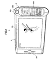
Fig. 1 is a perspective view illustrating an example of a
portable information terminal according to a preferred embodiment
of the present invention.
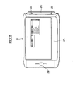
Fig. 2 is a front view illustrating a primary terminal of
the portable information terminal in the example in Fig. 1.
Fig. 3 is a rear view illustrating the primary terminal.
Fig. 4 is a front view illustrating a secondary terminal in
an open position when a display section is opened in relation to
a secondary operating section in accordance with the embodiment.
Fig. 5 is a rear view of the secondary terminal.
Fig. 6 is a block diagram illustrating the circuit
configuration of the primary terminal in accordance with the
embodiment.
Fig. 7 is a block diagram illustrating the circuit
configuration of the secondary terminal in accordance with the
embodiment.
Fig. 8 is a front view illustrating an example of usage
patterns of the portable information terminal in combination mode
in accordance with the embodiment.
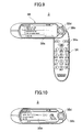
Fig. 9 is a front view illustrating an example of usage
patterns of the secondary terminal according to the embodiment.
Fig. 10 is a front view illustrating another example of the
usage patterns of the secondary terminal according to the
embodiment.
Fig. 11A is a rear view illustrating a usage pattern of the
secondary terminal with a CCD camera according to the embodiment.
Fig. 11B is a front view of the usage pattern in Fig. 11A.
Fig. 12 is a front view illustrating an example of usage
patterns of the portable information terminal as a navigation
system according to the embodiment.
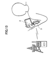
Fig. 13 is a diagram for explaining how to use the portable
information terminal as the navigation system relating to Fig.
12.
DETAILED DESCRIPTION OF THE PREFERRED EMBODIMENT
A preferred embodiment according to the present invention
will be described hereinafter in detail with reference to the
accompanying drawings.
Fig. 1 is a perspective view illustrating an example of
portable information terminal according to a preferred embodiment
of the present invention. Fig. 2 is a front view illustrating a
primary terminal forming part of the portable information terminal
in Fig. 1. Fig. 3 is a rear view illustrating the primary terminal.
Fig. 4 is a front view illustrating a secondary terminal forming
part of the portable information terminal in one of its usage
patterns. Fig. 5 is a rear view of the secondary terminal.
In Fig. 1, the portable information terminal 1 is constructed
of two parts, a primary terminal 2 and a secondary terminal 3
separably combined with the primary terminal 2.
As illustrated in Fig. 2, the primary terminal 2 has a
substantially quadrangular plate-shaped outside shape, on the
front surface of which a display panel 2A having a size occupying
most of a central area of the front surface is located, and four
operation keys 2B are arranged on a frame situated on the left
of the display panel 2A.
The primary terminal 2 has on the right edge thereof a mounting
base 2C which is formed into a recess shape corresponding to a
shape of the left edge of the secondary terminal 3 to fit with
the secondary terminal 3 for combined use. The mounting base 2C
incorporates a pair of combination detection sensors 2D for
detecting that the secondary terminal 3 is attached in place.
As illustrated in Fig. 3, on the back of the primary terminal
2, a DVD drive 2E is mounted, together with a card interface,
speaker, and headphone terminal which are not shown.
As illustrated in Fig. 4, the secondary terminal 3 includes
an elongated and approximately oval plate-shaped secondary
manipulation part 3A, and a plate-shaped display part 3B having
approximately the same outside shape as that of the secondary
manipulation part 3A. The display part 3B has a bottom end coupled
rotatably to a top end of the secondary manipulation part 3A through
a rotation supporting element 3C.
With this coupling, as described later, the display part 3B
moves rotatavely in relation to the secondary manipulation part
3A from a closed position in which the display part 3B and the
secondary manipulation part 3A are superimposed on each other,
to a first open position in which the part 3B is opened to form
a substantially right angle with the part 3A, or a second open
position in which the part 3B is opened an angle of 180 degrees
from the part 3A.
The secondary manipulation part 3A of the secondary terminal
3 includes a variety of operation keys 3Aa with a ten-key pad
required for the origination and reception of telephone calls which
are arranged over the front surface thereof, and a microphone 3Ab
in a lower portion of the front surface thereof (the portion
opposite to the portion supported by the rotational supporting
element 3C).
A card interface 3Ac is mounted in a central portion on the
back of the secondary manipulation part 3A, as illustrated in Fig
5. A CCD camera 3Ad is mounted in a lower portion of the back of
the part 3A (the portion opposite to the portion supported by the
rotational supporting element 3C) so as to slide between the
position in which the camera 3Ad is housed in a casing of the
secondary manipulation part 3A and the position in which the camera
3Ad is projected outward from the casing of the part 3A along the
axis of the part 3A.
A headphone terminal 3Ae is also mounted on a left side of
the back of the secondary manipulation part 3A when viewed from
the back thereof.
The display part 3B of the secondary terminal 3 includes on
the front thereof a display panel 3Ba having a size occupying most
of a central portion of the part 3B, and a speaker 3Bb at a top
end thereof.
The display part 3B further includes a jog dial 3Bc and a
joystick 3Bd at the bottom end thereof (the portion supported by
the rotational supporting element 3C). The jog dial 3Bc has an
outer edge which protrudes and is visible from the bottom end of
the display part 3B, and is placed concentrically with the
rotational supporting element 3C and rotatably in both directions.
The joystick 3Bd is provided on the same axis as that of the
rotational supporting element 3C.
The rotational supporting element 3C of the secondary
terminal 3 includes a rotational position detection sensor,
described later, for detecting in which position of the
aforementioned three positions, the closed position, first open
position and second open position, the display part 3B is situated
in relation to the secondary manipulation part 3A.
Fig. 6 is a block diagram illustrating an example of the
configuration of a control section incorporated in the primary
terminal 2 of the portable information terminal 1.
Referring to Fig. 6, a CPU 20 is connected through a display
driver 21 to the display panel 2A, and through an audio driver
22 to a speaker 2F and a headphone terminal 2G. The CPU 20 is
further connected to: the combination detection sensors 2D; a DVD
driver 2E for loading a DVD recording medium such as a DVD-R, DVD-RW,
DVD-ROM or DVD-RAM (an 8-cm DVD-R or an 8-cm DVD-RW in the example);
a card interface 2H for loading a memory card such as a SmartMedia,
compact flash, memory stick or multimedia card; a ROM 23 for storing
driver software programs for driving the devices connected to the
CPU 20, and the like; a RAM 24 for storing data; the operation
keys 2B; and a navigation ROM 25 for storing an application program
for a navigation system.
The CPU 20 is further connected to an antenna 26, incorporated
inside the casing of the primary terminal 2, through a data
processing circuit 28 and a communication circuit 27. The data
processing circuit 28 acts as a clock control for various signals
transmitted from and received by the communication circuit 27,
and serves as an interface of the CPU.
In the control section of the primary terminal 2 of the
portable information terminal 1, the antenna 26 provides for
communication, based on Bluetooth technology or the like, between
the primary terminal 2 and the secondary terminal 3 for the mutual
transmission and reception of data or programs and of signals for
controlling each other. The CPU 20 exercises control over various
controls: for transmitting various kinds of data accumulated in
the RAM 24 and various programs such as JAVA applet and the like
from the antenna 26 to the secondary terminal 3; for writing the
data transmitted from the secondary terminal 3 through the antenna
26, on the RAM 24, on a DVD recording medium loaded in the DVD
driver 2E, or on a memory card loaded in the card interface 2H;
for mutual remote control between the CPU 20 and the secondary
terminal 3 via the antenna 26 executed under various programs
installed in the secondary terminal 3; and the like.
The CPU 20 further exercises control over operational
controls for various functions installed in the primary terminal
2, for example, the launching of an application program stored
in the RAM 24, a DVD recording medium loaded in the DVD driver
2E or a memory card loaded in the card interface 2H on the basis
of an actuating signal inputted through the manipulation of the
operation keys 2B; the displaying of a video or an image on the
display panel 2A on the basis of the data stored in those recording
mediums; the outputting of audio to the speaker 2F or a headphone
connected to the headphone terminal 2G; and the executing of an
application program for navigation recorded in the navigation ROM
25; and the like.
The CPU 20 also exercises control over a systematic sharing
of operation between the primary terminal 2 and the secondary
terminal 3, as described later, when the secondary terminal 3 is
attached to the primary terminal 2 and the CPU 20 receives from
the combination detection sensor pairs 2D a detection signal
representing the attachment of the secondary terminal 3.
Fig. 7 is a block diagram illustrating an example of the
configuration of a control section incorporated in the secondary
terminal 3 of the portable information terminal 1.
Referring to Fig. 7, a CPU 30 is connected through a display
driver 31 to the display panel 3Ba, and through an audio driver
32 to the speaker 3Bb and the headphone terminal 3Ae, and also
through a signal processing circuit 33 to the CCD camera 3Ad. The
CPU 30 is further connected to a rotational position detection
sensor 34 of the display part 3B; a card interface 3Ac for loading
a memory card such as a SmartMedia, compact flash, memory stick,
and multimedia card; a ROM 35 for storing driver software programs
for driving the devices connected to the CPU 30, and the like;
a RAM 36 for storing application programs and data; the operation
keys 3Aa; the joystick 3Bd; and the jog dial 3Bc.
The CPU 30 is further connected to an antenna 37, incorporated
inside the casing of the secondary terminal 3, through a data
processing circuit 39 and a communication circuit 38. The data
processing circuit 39 acts as a clock control for various signals
transmitted from and received by the communication circuit 38 and
serves as an interface of the CPU.
The audio driver 32 is connected through an audio codec 40
to the microphone 3Ab and a ringer 41.
In the control section of the secondary terminal 3 of the
portable information terminal 1, the antenna 37 provides for
communication, based on Bluetooth technology or the like, between
the primary terminal 2 and the secondary terminal 3 for the mutual
transmission and reception of data or programs and of signals for
controlling each other, and also provides for connection to
computer networks such as the Internet or the like. The CPU 30
exercises control over a variety of controls: for transmitting
various kinds of data and various programs such as JAVA applet
and the like accumulated in the RAM 36, from the antenna 37 to
the primary terminal 2; for writing the data or programs
transmitted from the primary terminal 2 through the antenna 37
on the RAM 36 or on a memory card loaded in the card interface
3Ac; for mutual remote control between the CPU 30 and the primary
terminal 2 via the antenna 37 executed under various programs
installed in the secondary terminal 3; for connecting to the
computer networks; and the like.
The CPU 30 further exercises control over operational
controls for various functions installed in the secondary terminal
3, for example, execution of an application program stored in the
RAM 36 or in a memory card loaded in the card interface 3Ac on
the basis of an actuating signal inputted through the manipulation
of the operation keys 3Aa, jog dial 3Bc or joystick 3Bd; the
displaying of a video or an image on the display panel 3Ba on the
basis of the data stored on those recording mediums; outputting
of audio to the speaker 3Bb or headphones connected to the headphone
terminal 3Ae; the inputting of audio from the microphone 3Ab
through an audio codec 40 and the audio driver 32; the outputting
of audio to the ringer 41 through the audio driver 32 and the audio
codec 40; the photographing of the CCD camera 3Ad; and the storing
of data of the image photographed by the CCD camera 3Ad in the
RAM 36 or a memory card loaded in the card interface 3Ac.
The CPU 30 also controls the switching to operational mode
corresponding to each position of the display part 3B as described
later, on the basis of a detection signal representing a rotational
position of the display part 3B of the secondary terminal 3 in
relation to the secondary manipulation part 3A which is detected
by the rotational position detection sensor 34.
Next, the operation of the aforementioned portable
information terminal 1 will be described for each usage pattern
of the primary terminal 2 and the secondary terminal 3.
Functions installed in the primary terminal 2 are based on
the application programs stored in the ROM 23, RAM 24 and navigation
ROM 25, and the application programs stored on a DVD recording
medium loaded in the DVD driver 2E or a memory card loaded in the
card interface 2H. The user therefore can customize the
configuration of functions installed in the portable information
terminal 1 to make the functional configuration desirable by
rewriting the application program in the RAM 24 or changing the
DVD recording mediums or the memory cards.
Likewise, functions installed in the secondary terminal 3
are based on the application programs stored in the ROM 35 and
RAM 36, and the application programs stored on a memory card loaded
in the card interface 3Ac. The user can customize the
configuration of functions installed in the portable information
terminal 1 to make the functional configuration desirable by
rewriting the application program in the RAM 36 or changing the
memory cards.
First, with reference to Fig. 1 and Fig. 8, a description
will be given for usage patterns in combination mode in which the
secondary terminal 3 is placed on the mounting base 2C of the
primary terminal 2 for combination with the primary terminal 2.
Fig. 1 illustrates the usage pattern when the display part
3B of the secondary terminal 3 combined with the primary terminal
2 is in the closed position (i.e. the display part 3B and the
secondary manipulation part 3A are superimposed on each other).
Fig. 8 illustrates the usage pattern when the display part
3B of the secondary terminal 3 is in the first open position in
relation to the secondary manipulation part 3A (i.e. the display
part 3B is moved to form a right angle with the secondary
manipulation part 3A), and is set in parallel to the top edge of
the display 2A.
In the above usage pattern in combination, the combination
detection sensor pairs 2D mounted on the mounting base 2C detects
that the secondary terminal 3 is fitted into the mounting base
2C, and then sends a resulting combination detection signal
representing the combination of the secondary terminal 3 with the
CPU 20, and thus the primary terminal 2 recognizes the combination
of the secondary terminal 3.
The combination between the primary terminal 2 and the
secondary terminal 3 is secured by means of an engagement of an
engaging element, provided in the mounting base 2C, with the
secondary terminal 3 or of magnetic attraction between the
secondary terminal 3 and the mounting base 2C.
Upon the detection of the combination with the secondary
terminal 3, the CPU 20 switches to combination mode, and a Bluetooth
communication is established between the antenna 26 of the primary
terminal 2 and the antenna 37 of the secondary terminal 3 to conduct
remote control between the CPU 20 and the CPU 30 of the secondary
terminal 3, thereby enabling the user to operate the secondary
terminal 3 from the operation keys 2B of the primary terminal 2,
and to operate the primary terminal 2 from the operation keys 3Aa,
jog dial 3Bc or joystick 3Bd of the secondary terminal 3.
Thus, it is possible for a variety of application programs
installed in the primary terminal 2 and secondary terminal 3 to
implement the so-called "multi-play" capabilities established by
means of the systematic link between the displays and operation
sections, such as the operation keys, of both primary and secondary
terminals 2 and 3, resulting in allowing the portable information
terminal 1 to fully function as a mobile computer.
With the "multi-play" capability, the portable information
terminal 1 can execute a variety of operations, for example: the
terminal 1 is connected to the Internet by using a connecting
function of the secondary terminal 3 and displays the Web page
on the larger-size display panel 2A of the primary terminal 2;
and the terminal 1 displays data of addresses registered in the
secondary terminal 3 or data of an image photographed by the CCD
camera 3Ad of the terminal 3, on the display 2A of the primary
terminal 2 for editing; or the like.
In combination mode when the primary terminal 2 and secondary
terminal 3 are combined, the display 2A and the display 3Ba form
a double window. Through the use of the double window, for example,
the display 3Ba of the secondary terminal 3 having a screen smaller
in area than that of the display 2A of the primary terminal 2 can
be used as an auxiliary window such as a display window for
displaying a list of folders in the upper hierarchy, as a character
window for displaying a character set to allow the user to choose
a symbol or the like required for creating the document on the
display 2A, a guide window for displaying a key guide and the like,
and the like. Thus, with the double window, the display space of
the display 2A of the primary terminal 2 is smaller than that of
the display of a notebook-type personal computer, but can be
effectively used, leading to the creation of a smooth and mobile
computing.
Fig. 8 illustrates another example of the usage patterns of
the portable information terminal 1 serving as mobile computing
due to the double window. When the display part 3B of the secondary
terminal 3 is in the first open position in relation to the
secondary manipulation part 3A (i.e. the display part 3B is opened
to form a right angle with the secondary manipulation part 3A) and
the display 3Ba is laid over and in parallel to the top edge of
the display 2A, the portable information terminal 1 can display
icons indicating kinds of databases or a variety of toolbars on
the display 3Ba, to provide an operational screen equivalent to
that of a general personal computer.
In this first open position, the operation keys 3Aa arranged
on the secondary manipulation part 3A of the secondary terminal
3 are on view and available for use. Hence, the secondary
manipulation part 3A is used as a keyboard and the operation keys
2B of the primary terminal 2 are used as cursor keys, and also
the jog dial 3Bc and the joystick 3Bd of the secondary terminal
is used on behalf of a mouse, thereby allowing the portable
information computer 1 to serve as a mobile computer in a usage
pattern similar to that of a notebook-type personal computer.
As described above, when the display part 3B of the secondary
terminal 3 is opened or closed in relation to the secondary
manipulation part 3A to change the usage patterns of the portable
information terminal 1, the rotational position detection sensor
34 (see Fig. 7) detects the position of the display part 3B of the
secondary terminal 3 in relation to the secondary manipulation
part 3A, and applies a detected rotational position detection
signal to the CPU 30. Then, the CPU 30 transmits the detected
signal to the CPU 20 of the primary terminal 2 by way of the Bluetooth
communication, and then the primary terminal 2 and the secondary
terminal 3 are automatically switched into the mode corresponding
to the usage pattern in each rotational position.
Next, a description will be given of a usage pattern when
the combined primary terminal 2 and secondary terminal 3 are
separated to be used individually.
Fig. 2 illustrates an example of usage patterns when the
primary terminal 2 is used alone.
The primary terminal 2 serves as a DVD player when a DVD
software is mounted on the DVD drive 2E provided on the back of
the primary terminal 2 (see Fig. 3). In this case, the operation
keys 2B are respectively allocated the functions of "play", "stop",
"fast forward" and "fast backward", for example.
The primary terminal 2 can be used in various patterns, for
example, as a television receiver when a memory card having a TV
receiving capability is loaded in the card interface 2H, and as
an image display if a certain memory card having a required
capability is loaded.
Each of Figs. 4, 9, 10, 11A and 11B illustrates an example
of usage patterns when the secondary terminal 3 is used alone.
Fig. 4 illustrates a usage pattern when the display part 3B
of the secondary terminal 3 is in the second open position in
relation to the secondary manipulation part 3A (i.e. the display
part 3B is opened 180 degrees from the secondary manipulation part
3A).
In the second open position, the secondary terminal 3 has
the maximum distance between the microphone 3Ab incorporated in
the bottom end of the secondary manipulation part 3A and the speaker
3Bb incorporated in the top end of the display part 3B, and the
operation keys 3Aa of the secondary manipulation part 3A are on
view and available for use. Accordingly, the second open position
allows the secondary terminal 3 to be used as a speech communication
device such as a portable telephone or the like.
Fig. 9 illustrates an example of the usage patterns when the
display part 3B of the secondary terminal 3 is in the first open
position in relation to the secondary manipulation part 3A (i.e.
the display part 3B is opened to form a right angle with the
secondary manipulation part 3A).
In this first open position, the secondary terminal 3 can
be used on the basis of the function corresponding to, for example,
transmission/receipt mode for an electronic mail in which the
built-in communication circuit 37 (see Fig. 7) establishes
connection with the Internet; remote-control mode for remotely
controlling a domestic appliance or the like through the Bluetooth
communication; or credit-payment mode for paying at a convenience
store, vending machine, ticket machine or the like.
Fig. 10 illustrates an example of the usage patterns when
the display part 3B of the secondary terminal 3 is in the closed
position relative to the secondary manipulation part 3A (i.e. the
display part 3B and the secondary manipulation part 3A are
superimposed on each other).
In the usage pattern in the closed position, the secondary
terminal 3 is used as a music player as shown in Fig. 10 by way
of example. If the user connects headphones to the headphone
terminal 3Ae, he/she can enjoy listening to music on the basis
of MPEG4 or the like.
Figs. 11A and 11B illustrate another example of the usage
patterns when the display part 3B of the secondary terminal 3 is
in the closed position relative to the secondary manipulation part
3A.
As illustrated in Fig. 11A, the secondary terminal 3 in the
usage pattern can is used as a digital camera when the CCD camera
3Ad mounted on the back of the secondary terminal 3 is slid out
from the casing to set a lens in a correct position for exposure.
In this use, the CPU 30 determines from a detection signal
sent from a sensor (not shown) that the CCD camera 3Ad has been
slid out from the casing, and automatically switches into camera
mode.
As shown in Fig. 11B, then, thumbnail images of the images
photographed by the CCD camera 3Ad are displayed on the display
3Ba of the display part 3B to allow the user to check the
photographed images.
In the aforementioned usage patterns of the secondary
terminal 3 separated from the primary terminal 2, various operating
methods can be implemented, in which, for example, the secondary
terminal 3 reads and activates the application programs stored
in the RAM 36 (see Fig. 7) to perform a variety of functions, and
various kinds of data subject to manipulation on the secondary
terminal 3 are retained in the RAM 24 of the primary terminal 2
and only the data required for manipulation on the secondary
terminal 3 is copied from the RAM 24 into the RAM 36 of the secondary
terminal 3 as occasion requires.
The secondary terminal 3 can transmit a program or data
downloaded through the Internet or the like, image data of
photographs taken by the CCD camera 3Ad and required to be stored,
or the like, to the primary terminal 2 for storing as appropriate.
Such various operating methods achieve the effective use for
programs and data of a storage region of the RAM 36 of the secondary
terminal 3 which has a storage capacity smaller than that of the
primary terminal 2, and allow distributed storage of data in the
primary terminal 2 and the secondary terminal 3. Thus, the present
invention can overcomes the security problems associated with the
carrying of various kinds of data.
The transmission and receipt of the application programs and
various kinds of data between the primary terminal 2 and the
secondary terminal 3 as described above, are performed through
the Bluetooth communication between the primary and secondary
terminals either when the primary terminal 2 and secondary terminal
3 are combined together or when they are separated from each other.
Fig. 12 illustrates an example of usage patterns when the
portable information terminal 1 serves as a handy navigation system
by means of the systematic link between the primary terminal 2
and the secondary terminal 3.
The usage pattern in Fig. 12 can be performed either when
the primary terminal 2 and secondary terminal 3 are combined
together or when they are separated from each other as shown in
Fig. 12.
Specifically, in the primary terminal 2, a DVD recording map
images is loaded in the DVD drive 2E, and the navigation application
program stored in the navigation ROM 25 is activated to display
the navigation map image on the display 2A.
A present position of the terminal is detected by a
communication function provided in the secondary terminal 3. For
example, a memory card having a GPS function is loaded in the card
interface 3Ac of the secondary terminal 3 and the GPS function
is used for detecting the present position.
Alternatively, as illustrated in Fig. 13, the PHS
communication function or the Bluetooth communication function
incorporated in the secondary terminal 3 establishes
communication with PHS (personal handyphone system) relay antennas
or communication with sales-managing communication antennas
attached to vending machines or the like, to detect the present
position, and the positional information detected by either the
PHS or the Bluetooth communication function is transmitted to the
primary terminal 2 by way of the Bluetooth communication. The
primary terminal 2 displays a mark indicating the present position
on the map data image displayed on the display 2A for guidance
to the destination.
The terms and description used herein are set forth by way
of illustration only and are not meant as limitations. Those
skilled in the art will recognize that numerous variations are
possible within the spirit and scope of the invention as defined
in the following claims.