EP1271232A2 - Storage phosphor cassette - Google Patents
Storage phosphor cassette Download PDFInfo
- Publication number
- EP1271232A2 EP1271232A2 EP02077400A EP02077400A EP1271232A2 EP 1271232 A2 EP1271232 A2 EP 1271232A2 EP 02077400 A EP02077400 A EP 02077400A EP 02077400 A EP02077400 A EP 02077400A EP 1271232 A2 EP1271232 A2 EP 1271232A2
- Authority
- EP
- European Patent Office
- Prior art keywords
- end member
- back end
- edge
- cassette
- insert plate
- Prior art date
- Legal status (The legal status is an assumption and is not a legal conclusion. Google has not performed a legal analysis and makes no representation as to the accuracy of the status listed.)
- Granted
Links
Images




Classifications
-
- G—PHYSICS
- G03—PHOTOGRAPHY; CINEMATOGRAPHY; ANALOGOUS TECHNIQUES USING WAVES OTHER THAN OPTICAL WAVES; ELECTROGRAPHY; HOLOGRAPHY
- G03B—APPARATUS OR ARRANGEMENTS FOR TAKING PHOTOGRAPHS OR FOR PROJECTING OR VIEWING THEM; APPARATUS OR ARRANGEMENTS EMPLOYING ANALOGOUS TECHNIQUES USING WAVES OTHER THAN OPTICAL WAVES; ACCESSORIES THEREFOR
- G03B42/00—Obtaining records using waves other than optical waves; Visualisation of such records by using optical means
- G03B42/02—Obtaining records using waves other than optical waves; Visualisation of such records by using optical means using X-rays
- G03B42/04—Holders for X-ray films
Definitions
- the present invention relates generally to cassettes for photographic elements, and more particularly, to an x-ray cassette used in computed radiography.
- a photographic element In the field of computed radiography, a photographic element has an image formed thereon by x-rays. The photographic element is subsequently provided to a reader wherein the element is stimulated to emit a radiation pattern that is indicative of the image formed by the x-rays.
- storage phosphors are used to capture radiographic images from incident x-rays. Most radiographic procedures are carried out within normal room lighting conditions, accordingly, a primary requirement for any computed radiography x-ray cassette is to shield the storage phosphor from exposure by ambient light.
- Cassettes of the kind used in computed radiography may comprise a container having an upper and lower parts that are hinged together so that they can be opened for insertion of a flexible film sheet or a rigid film plate comprising the photographic element.
- the cassette is closed and latched so that the cassette with the element therein can be used with an x-ray apparatus to produce an image on the photographic element.
- the cassette is taken to a reader where the cassette is opened and the photographic element extracted by suitable feeders, such as a suction feeding device.
- suitable feeders such as a suction feeding device.
- the photographic element separates from the cassette, and is transported through the reader where it is stimulated to emit a radiation pattern which is captured for storage and use.
- the radiation pattern is subsequently erased from the photographic element before being returned to the cassette for re-use.
- cassettes While such cassettes may have achieved certain degrees of success in their particular applications, cassettes are susceptible to various types of damage when dropped or roughly handled. Accordingly, it is desirable to increase the durability of the cassette while minimizing cost and weight, and preserving the same basic nature of design.
- An object of the present invention is to provide a cassette which has increased durability, and is resistant to damage when dropped or roughly handled.
- a x-ray cassette comprising a shell and a storage phosphor assembly.
- the shell comprises an upper and lower panel, a first and second side member, and a front end member, with the first and second side members and front end member joining the upper and lower panels to define a cavity having an open end.
- the storage phosphor assembly comprises an insert plate having a first and second side, a back end member having two ends, and a first and second edge insert.
- the storage phosphor assembly is adapted to be removably contained within the shell such that the back end member closes off the open end of the shell.
- the first and second edge inserts are affixed to the first and second sides, respectively.
- the back end member has at each end an extension extending in a direction parallel to the length of the back end member to interlock the back end member with the first and second edge inserts such that the force of an impact to the cassette is transferred to the back end member rather than to the insert plate to avoid buckling thereof.
- the present invention provides a cassette which has increased durability and reduced susceptibility to damage when dropped or roughly handled.
- FIG. 1 shows a perspective view of a storage phosphor cassette in accordance with the present invention.
- FIG. 2 shows a bottom view of the cassette of FIG. 1.
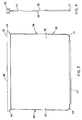
- FIG. 3 shows a top view of the storage phosphor assembly of the cassette of FIG. 1.
- FIG. 4 shows a side view of the storage phosphor assembly of FIG. 3.
- FIG. 5 shows a bottom view of a corner of the cassette of FIG. 2.
- FIG. 6 shows a perspective view of a corner of the cassette of FIG. 2.
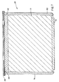
- FIG. 7 shows a cross sectional view of the insert plate of the storage phosphor assembly of FIG. 3 taken along the plane of the insert plate.
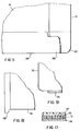
- FIG. 8 shows a top view of a corner of the insert plate of the storage phosphor assembly of FIG. 3.
- FIG. 9 shows a top view of another corner of the insert plate of the storage phosphor assembly of FIG. 3.
- FIG. 10 shows a cross sectional view of insert plate of the storage phosphor assembly of FIG. 3 taken transverse to the plane of the insert plate.
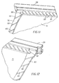
- FIG. 11 shows a perspective view of a corner of the of insert plate of the storage phosphor assembly of FIG. 7.
- FIG. 12 shows a perspective view of another corner of the insert plate of the storage phosphor assembly of FIG. 7.
- FIG. 13 shows a perspective view of the back end member of the storage phosphor assembly of FIG. 7.
- FIGS 1-4 show a storage phosphor cassette 10 in accordance with the present invention.
- Cassette 10 includes a shell 12 comprising an upper panel 14, a lower panel 16, a first side member 18, a second side member 20, and a front end member 22.
- Upper and lower panels 14,16 are preferably rectangular in shape.
- First side member 18, second side member 20, and front end member 22 join upper and lower panels 14,16 to form a five-sided cavity having an open end 24.
- Cassette 10 further includes a storage phosphor assembly 26 having a front edge 27, a back end member 28, an insert plate 30 having an upper face and being cantilevered from back end member 28, and a storage phosphor 32 disposed on the upper face of insert plate 30.
- a front edge of insert plate 30 includes corners 68,70, which are preferably rounded.
- Back end member 28 includes apertures 29,31 for access to the interior of back end member 28 to latch and unlatch a latch bar 50 slidably mounted therein.
- Storage phosphor assembly 26 is removably contained within the cavity of shell 12 such that back end member 28 of storage phosphor assembly 26 closes off open end 24 of shell 12, thereby providing a light-tight enclosure for storage phosphor 32.
- Back end member 28 of storage phosphor assembly 26 includes end portions 64,66.
- First and second side members 18,20 include a corner structure 60,62, respectively, which respectively engage end portions 64,66.
- Corner structures 60,62 can be integral with first and second side members 18,20, or as illustrated, can be separate corner pieces which are secured to first and second side members 18,20.
- End portions 64,66 and respective corner structures 60,62 have complimentary, interlocking configurations, such that, should cassette 10 be dropped and a force exerted on either corner structure 60,62, the force is transferred to storage phosphor assembly 26, forcing assembly 26 into shell 12. Corner structure 62 engaged with end portion 66 is further illustrated in Figures 5-6.
- insert plate 30 is comprised of a lightweight rigid structure including an aluminum honeycomb core 71 and outer aluminum skins 72,74.
- the edge of honeycomb core 71 is milled out (recessed) around the entire perimeter to create a cavity.
- edge inserts 76,78,80 are each glued into a side of the cavity formed in the honeycomb structure.
- Back end member 28 is inserted to a fourth side of the cavity formed in the honeycomb structure.
- One end of edge insert 76 interlocks with back end member 28 by means of a connector 90 which can be, for example, a key or leg.
- edge insert 80 interlocks with back end member 28 by means of a connector 92 which can be, for example, key or leg.
- connectors 90,92 are each shown as a leg of back end member 28 extending into edge inserts 76,80 in a direction parallel to the length of back end member 28, which is transverse to the length of edge inserts 76,80, respectively.
- Edge inserts 76,80 comprise a complimentary recess to mate with connectors 90,92.
- the interlocking arrangement of edge inserts 76,80 with back end member 28 transfers a force from a side impact to cassette 10 to back end member 28 rather than buckling outer aluminum skins 72,74.
- This interlocking arrangement of edge inserts 76,80 also serves to capture back end member 28 so as to prevent it from being separated or loosened from honeycomb core 71 during rough handling, or from a force which attempts to dislocate it.
- edge inserts 76,80 may optionally comprise a plurality of shallow slots or channels 93 disposed on at least one of its surfaces. Such channels 93 promote adhesion of the edge inserts with insert plate 30 since they provide additional surface area for the glue to migrate and adhere rather than being directed to the cells of the honeycomb. As illustrated, channels 93 form an angle relative to an edge of edge inserts 76, 80. A cross-hatch pattern might also be employed.
- back end member 28 may also optionally comprise channels 93, with channels 93 being angled relative to an edge of back end member 28.
- edge inserts 76,80 extend slightly beyond the perimeter of outer aluminum skins 72,74 (as shown in Figure 3 at 94,96, respectively) thereby creating a shock absorption system to absorb and distribute forces on insert plate 30. If edge inserts 76,80 extend beyond the perimeter of outer aluminum skins 72,74, then preferably channels 93 are disposed on that portion of edge inserts 76,80 which do not extend beyond the perimeter, but rather, are disposed on that portion of edge inserts 76,80 internal to honeycomb core 71.
- edge inserts 76,80 are of aluminum
- edge insert 78 is of a polymeric material
- back end member 28 is of an aluminum material.
Landscapes
- Physics & Mathematics (AREA)
- General Physics & Mathematics (AREA)
- Radiography Using Non-Light Waves (AREA)
- Conversion Of X-Rays Into Visible Images (AREA)
Abstract
Description
Claims (10)
- An x-ray cassette, comprising:a shell comprising an upper and lower panel, a first and second side member, and a front end member, the first and second side members and front end member joining the upper and lower panels to define a cavity having an open end;a storage phosphor assembly comprising an insert plate having a first and second side, a back end member having two ends, and a first and second edge insert, the storage phosphor assembly adapted to be removably contained within the shell such that the back end member closes off the open end of the shell, the first and second edge inserts being affixed to the first and second sides, respectively, the back end member having at each end an extension extending in a direction parallel to the length of the back end member to interlock the back end member with the first and second edge inserts such that the force of an impact to the cassette is transferred to the back end member rather than to the insert plate to avoid buckling thereof.
- The x-ray cassette of Claim 1, wherein the insert plate includes outer aluminum skins sandwiching a core.
- The x-ray cassette of Claim 2, wherein the first and second edge inserts extend beyond the perimeter of the aluminum skins, thereby creating a shock absorption system to absorb and distribute forces exerted on the insert plate.
- The x-ray cassette of Claim 2, wherein the edges of the core are recessed from the edges of the outer aluminum skins to create a cavity along the first and second side.
- The x-ray cassette of Claim 1, wherein the first and second edge inserts each comprise at least one shallow channel disposed thereon.
- The x-ray cassette of Claim 5, wherein the channel is disposed at an angle relative to an edge of the first or second edge insert.
- The x-ray cassette of Claim 1, wherein the back end member comprises at least one shallow channel disposed thereon.
- The x-ray cassette of Claim 7, wherein the channel is disposed at an angle relative to an edge of the back end member.
- An x-ray cassette, comprising:a shell comprising an upper and lower panel, a first and second side member, and a front end member, the first and second side members and front end member joining the upper and lower panels to define a cavity having an open end;a storage phosphor assembly comprising an insert plate having a first and second side, a back end member having two ends, and a first and second edge insert, the storage phosphor assembly adapted to be removably contained within the shell such that the back end member closes off the open end of the shell, the first and second edge inserts being affixed to the first and second sides, respectively, the back end member having at each end an extension extending in a direction parallel to the length of the back end member to interlock the back end member with the first and second edge inserts to secure the back end member to the insert plate wherein a force of an impact to the cassette is transferred to the extensions of the back end member rather than to the insert plate to avoid separation of the back end member from the insert plate.
- The x-ray cassette of Claim 9, wherein the first and second edge inserts each comprise at least one shallow channel disposed thereon.
Applications Claiming Priority (2)
| Application Number | Priority Date | Filing Date | Title |
|---|---|---|---|
| US896625 | 2001-06-29 | ||
| US09/896,625 US6683315B2 (en) | 2001-06-29 | 2001-06-29 | Storage phosphor cassette |
Publications (3)
| Publication Number | Publication Date |
|---|---|
| EP1271232A2 true EP1271232A2 (en) | 2003-01-02 |
| EP1271232A3 EP1271232A3 (en) | 2003-01-15 |
| EP1271232B1 EP1271232B1 (en) | 2004-09-08 |
Family
ID=25406522
Family Applications (1)
| Application Number | Title | Priority Date | Filing Date |
|---|---|---|---|
| EP02077400A Expired - Lifetime EP1271232B1 (en) | 2001-06-29 | 2002-06-17 | Storage phosphor cassette |
Country Status (4)
| Country | Link |
|---|---|
| US (1) | US6683315B2 (en) |
| EP (1) | EP1271232B1 (en) |
| JP (1) | JP2003029364A (en) |
| DE (1) | DE60201153T2 (en) |
Families Citing this family (8)
| Publication number | Priority date | Publication date | Assignee | Title |
|---|---|---|---|---|
| ATE363671T1 (en) * | 2001-12-20 | 2007-06-15 | Agfa Gevaert Healthcare Gmbh | MEMORY FLUORESCENT FILM FOR X-RAY PHOTOGRAPHS |
| RU2256403C1 (en) * | 2004-03-15 | 2005-07-20 | Резник Константин Анатольевич | Universal medical x-ray cassette |
| US7087909B2 (en) * | 2004-10-28 | 2006-08-08 | Eastman Kodak Company | Storage phosphor cassette |
| US7446331B2 (en) * | 2006-08-21 | 2008-11-04 | Carestream Health, Inc. | Apparatus for scanning stimulable phosphor medium |
| US7504651B2 (en) * | 2006-08-21 | 2009-03-17 | Carestream Health, Inc. | Sheet scanning apparatus |
| US7456419B2 (en) * | 2006-08-21 | 2008-11-25 | Carestream Health, Inc. | Radiation imaging cassette |
| US7935932B2 (en) * | 2008-01-31 | 2011-05-03 | Fujifilm Corporation | Radiation detection apparatus |
| US10244644B2 (en) * | 2015-12-04 | 2019-03-26 | Continental Automotive Systems, Inc. | Automotive electronic device having a cover with fins to reduce gel vibration |
Family Cites Families (11)
| Publication number | Priority date | Publication date | Assignee | Title |
|---|---|---|---|---|
| US4336678A (en) * | 1978-07-24 | 1982-06-29 | Peters Dierk D | I-Beam truss structure |
| US5034256A (en) | 1989-08-28 | 1991-07-23 | United Technologies Corporation | Closeout configuration for honeycomb core composite sandwich panels |
| DE69329611T2 (en) | 1992-08-19 | 2001-05-03 | Canon K.K., Tokio/Tokyo | Method of registration by means of a projecting optical system, exposure apparatus for its implementation and semiconductor manufacturing method using this exposure apparatus |
| US5712486A (en) * | 1996-04-15 | 1998-01-27 | Liberty Technologies, Inc. | Flexible cassette for holding storage phosphor screen |
| US5652781A (en) * | 1996-04-24 | 1997-07-29 | Eastman Kodak Company | Intensifying x-ray film cassette |
| US5869839A (en) * | 1997-05-23 | 1999-02-09 | Eastman Kodak Company | Storage phosphor cassette with enhanced features |
| US5861631A (en) * | 1997-05-23 | 1999-01-19 | Eastman Kodak Company | Storage phosphor cassette with improved durability |
| US5912944A (en) * | 1997-09-30 | 1999-06-15 | Eastman Kodak Company | X-ray cassette |
| US5943390A (en) * | 1997-09-30 | 1999-08-24 | Eastman Kodak Company | Storage phosphor cassette with reduced weight and cost |
| US6777691B2 (en) * | 2001-06-29 | 2004-08-17 | Eastman Kodak Company | Storage phosphor cassette |
| US20030001106A1 (en) * | 2001-06-29 | 2003-01-02 | Wendlandt William C. | Storage phosphor cassette |
-
2001
- 2001-06-29 US US09/896,625 patent/US6683315B2/en not_active Expired - Fee Related
-
2002
- 2002-06-14 JP JP2002174282A patent/JP2003029364A/en active Pending
- 2002-06-17 DE DE60201153T patent/DE60201153T2/en not_active Expired - Fee Related
- 2002-06-17 EP EP02077400A patent/EP1271232B1/en not_active Expired - Lifetime
Also Published As
| Publication number | Publication date |
|---|---|
| EP1271232A3 (en) | 2003-01-15 |
| JP2003029364A (en) | 2003-01-29 |
| EP1271232B1 (en) | 2004-09-08 |
| US6683315B2 (en) | 2004-01-27 |
| DE60201153D1 (en) | 2004-10-14 |
| DE60201153T2 (en) | 2005-11-03 |
| US20030001105A1 (en) | 2003-01-02 |
Similar Documents
| Publication | Publication Date | Title |
|---|---|---|
| EP0544138B1 (en) | X-ray cassette with removable photographic element | |
| US5869839A (en) | Storage phosphor cassette with enhanced features | |
| EP0158942B1 (en) | Cassette for stimulable phosphor sheet | |
| EP1271232B1 (en) | Storage phosphor cassette | |
| WO1997038917A1 (en) | Flexible cassette for holding storage phosphor screen | |
| US5861631A (en) | Storage phosphor cassette with improved durability | |
| EP0905715A1 (en) | Storage phosphor cassette with reduced weight and cost | |
| JPH0456301B2 (en) | ||
| EP1315030B1 (en) | Computed radiography cassette for mammography | |
| US6777691B2 (en) | Storage phosphor cassette | |
| US20030001106A1 (en) | Storage phosphor cassette | |
| EP1271230B1 (en) | Storage phosphor cassette with shock absorbing corner elements | |
| US6614032B2 (en) | Computed radiography cassette with x-ray transmissive edges | |
| EP0632319A1 (en) | Film cassette | |
| US7087909B2 (en) | Storage phosphor cassette | |
| US20040251596A1 (en) | Cassette for storage phosphor medium | |
| JP2002182322A (en) | Stimulable phosphor sheet and conveyance assisting member | |
| JPH0538352Y2 (en) | ||
| JPS62245246A (en) | Package for sheet film | |
| EP0675393A2 (en) | Photographic film packet and light locking element | |
| JP2004145073A (en) | Radiation image photographing apparatus | |
| JPH0566298B2 (en) | ||
| JPH0271199A (en) | Sheet of accumulative fluorescent substance | |
| JP2005084242A (en) | Destaticization structure of radiation cassette | |
| JPS62211645A (en) | Package for sheet film |
Legal Events
| Date | Code | Title | Description |
|---|---|---|---|
| PUAI | Public reference made under article 153(3) epc to a published international application that has entered the european phase |
Free format text: ORIGINAL CODE: 0009012 |
|
| PUAL | Search report despatched |
Free format text: ORIGINAL CODE: 0009013 |
|
| AK | Designated contracting states |
Kind code of ref document: A2 Designated state(s): AT BE CH CY DE DK ES FI FR GB GR IE IT LI LU MC NL PT SE TR |
|
| AX | Request for extension of the european patent |
Free format text: AL;LT;LV;MK;RO;SI |
|
| AK | Designated contracting states |
Kind code of ref document: A3 Designated state(s): AT BE CH CY DE DK ES FI FR GB GR IE IT LI LU MC NL PT SE TR |
|
| AX | Request for extension of the european patent |
Free format text: AL;LT;LV;MK;RO;SI |
|
| 17P | Request for examination filed |
Effective date: 20030623 |
|
| 17Q | First examination report despatched |
Effective date: 20030724 |
|
| AKX | Designation fees paid |
Designated state(s): DE FR GB |
|
| GRAP | Despatch of communication of intention to grant a patent |
Free format text: ORIGINAL CODE: EPIDOSNIGR1 |
|
| GRAS | Grant fee paid |
Free format text: ORIGINAL CODE: EPIDOSNIGR3 |
|
| GRAA | (expected) grant |
Free format text: ORIGINAL CODE: 0009210 |
|
| AK | Designated contracting states |
Kind code of ref document: B1 Designated state(s): DE FR GB |
|
| REG | Reference to a national code |
Ref country code: GB Ref legal event code: FG4D |
|
| REG | Reference to a national code |
Ref country code: IE Ref legal event code: FG4D |
|
| REF | Corresponds to: |
Ref document number: 60201153 Country of ref document: DE Date of ref document: 20041014 Kind code of ref document: P |
|
| ET | Fr: translation filed | ||
| PLBE | No opposition filed within time limit |
Free format text: ORIGINAL CODE: 0009261 |
|
| STAA | Information on the status of an ep patent application or granted ep patent |
Free format text: STATUS: NO OPPOSITION FILED WITHIN TIME LIMIT |
|
| 26N | No opposition filed |
Effective date: 20050609 |
|
| REG | Reference to a national code |
Ref country code: GB Ref legal event code: 732E |
|
| PGFP | Annual fee paid to national office [announced via postgrant information from national office to epo] |
Ref country code: DE Payment date: 20080630 Year of fee payment: 7 |
|
| PGFP | Annual fee paid to national office [announced via postgrant information from national office to epo] |
Ref country code: GB Payment date: 20080506 Year of fee payment: 7 |
|
| REG | Reference to a national code |
Ref country code: FR Ref legal event code: TP |
|
| GBPC | Gb: european patent ceased through non-payment of renewal fee |
Effective date: 20090617 |
|
| REG | Reference to a national code |
Ref country code: FR Ref legal event code: ST Effective date: 20100226 |
|
| PG25 | Lapsed in a contracting state [announced via postgrant information from national office to epo] |
Ref country code: FR Free format text: LAPSE BECAUSE OF NON-PAYMENT OF DUE FEES Effective date: 20090630 |
|
| PGFP | Annual fee paid to national office [announced via postgrant information from national office to epo] |
Ref country code: FR Payment date: 20080424 Year of fee payment: 7 |
|
| PG25 | Lapsed in a contracting state [announced via postgrant information from national office to epo] |
Ref country code: GB Free format text: LAPSE BECAUSE OF NON-PAYMENT OF DUE FEES Effective date: 20090617 |
|
| PG25 | Lapsed in a contracting state [announced via postgrant information from national office to epo] |
Ref country code: DE Free format text: LAPSE BECAUSE OF NON-PAYMENT OF DUE FEES Effective date: 20100101 |