EP1271230A1 - Storage phosphor cassette with shock absorbing corner elements - Google Patents
Storage phosphor cassette with shock absorbing corner elements Download PDFInfo
- Publication number
- EP1271230A1 EP1271230A1 EP02077370A EP02077370A EP1271230A1 EP 1271230 A1 EP1271230 A1 EP 1271230A1 EP 02077370 A EP02077370 A EP 02077370A EP 02077370 A EP02077370 A EP 02077370A EP 1271230 A1 EP1271230 A1 EP 1271230A1
- Authority
- EP
- European Patent Office
- Prior art keywords
- leg
- corner
- storage phosphor
- cavity
- cassette
- Prior art date
- Legal status (The legal status is an assumption and is not a legal conclusion. Google has not performed a legal analysis and makes no representation as to the accuracy of the status listed.)
- Granted
Links
- OAICVXFJPJFONN-UHFFFAOYSA-N Phosphorus Chemical compound [P] OAICVXFJPJFONN-UHFFFAOYSA-N 0.000 title claims abstract description 32
- 230000035939 shock Effects 0.000 title description 4
- 230000001154 acute effect Effects 0.000 claims description 6
- 238000002601 radiography Methods 0.000 description 5
- 238000003780 insertion Methods 0.000 description 3
- 230000037431 insertion Effects 0.000 description 3
- 239000000463 material Substances 0.000 description 3
- 230000005855 radiation Effects 0.000 description 3
- 239000006096 absorbing agent Substances 0.000 description 2
- 239000004743 Polypropylene Substances 0.000 description 1
- 238000010521 absorption reaction Methods 0.000 description 1
- 239000002131 composite material Substances 0.000 description 1
- 239000013536 elastomeric material Substances 0.000 description 1
- 238000001125 extrusion Methods 0.000 description 1
- 210000001503 joint Anatomy 0.000 description 1
- 230000013011 mating Effects 0.000 description 1
- 239000002184 metal Substances 0.000 description 1
- 238000000034 method Methods 0.000 description 1
- -1 polypropylene Polymers 0.000 description 1
- 229920001155 polypropylene Polymers 0.000 description 1
- 229920002635 polyurethane Polymers 0.000 description 1
- 239000004814 polyurethane Substances 0.000 description 1
- 229920002725 thermoplastic elastomer Polymers 0.000 description 1
- 239000012815 thermoplastic material Substances 0.000 description 1
- 229920001187 thermosetting polymer Polymers 0.000 description 1
Images




Classifications
-
- G—PHYSICS
- G03—PHOTOGRAPHY; CINEMATOGRAPHY; ANALOGOUS TECHNIQUES USING WAVES OTHER THAN OPTICAL WAVES; ELECTROGRAPHY; HOLOGRAPHY
- G03B—APPARATUS OR ARRANGEMENTS FOR TAKING PHOTOGRAPHS OR FOR PROJECTING OR VIEWING THEM; APPARATUS OR ARRANGEMENTS EMPLOYING ANALOGOUS TECHNIQUES USING WAVES OTHER THAN OPTICAL WAVES; ACCESSORIES THEREFOR
- G03B42/00—Obtaining records using waves other than optical waves; Visualisation of such records by using optical means
- G03B42/02—Obtaining records using waves other than optical waves; Visualisation of such records by using optical means using X-rays
- G03B42/04—Holders for X-ray films
Definitions
- the present invention relates generally to cassettes for photographic elements, and more particularly, to an x-ray cassette used in computed radiography.
- a photographic element In the field of computed radiography, a photographic element has an image formed thereon by x-rays. The photographic element is subsequently provided to a reader wherein the element is stimulated to emit a radiation pattern that is indicative of the image formed by the x-rays.
- storage phosphors are used to capture radiographic images from incident x-rays. Most radiographic procedures are carried out within normal room lighting conditions, accordingly, a primary requirement for any computed radiography x-ray cassette is to shield the storage phosphor from exposure by ambient light.
- Cassettes of the kind used in computed radiography may comprise a container having an upper and lower parts that are hinged together so that they can be opened for insertion of a flexible film sheet or a rigid film plate comprising the photographic element.
- the cassette is closed and latched so that the cassette with the element therein can be used with an x-ray apparatus to produce an image on the photographic element.
- the cassette is taken to a reader where the cassette is opened and the photographic element extracted by suitable feeders, such as a suction feeding device.
- suitable feeders such as a suction feeding device.
- the photographic element separates from the cassette, and is transported through the reader where it is stimulated to emit a radiation pattern which is captured for storage and use.
- the radiation pattern is subsequently erased from the photographic element before being returned to the cassette for re-use.
- cassettes While such cassettes may have achieved certain degrees of success in their particular applications, cassettes are susceptible to various types of damage when dropped or roughly handled. Accordingly, it is desirable to increase the durability of the cassette while minimizing cost and weight, and preserving the same basic nature of design.
- An object of the present invention is to provide a cassette which has increased durability, and is resistant to damage when dropped or roughly handled.
- Still another object of the invention is to provide such a cassette which provides light integrity by shielding the storage phosphor from exposure by ambient light, particularly when dropped, roughly handled, and/or damaged.
- a corner element for an x-ray cassette having an upper and lower panel, a first member joining the upper and lower panels to define a cavity therebetween, and a storage phosphor assembly adapted to be removably contained within the cavity.
- the comer element comprises an upper and lower corner channel for receiving, respectively, the upper and lower panels; and a first leg adapted to mate with the first member and having an inclined element integrally formed therewith, the storage phosphor assembly being disposed adjacent to the inclined element when contained within the cavity.
- an x-ray cassette includes a shell comprising an upper and lower panel, a first and second side member, and a front end member, the first and second side members and front end member joining the upper and lower panels to define a cavity; a storage phosphor assembly adapted to be removably contained within the cavity; and a corner element.
- the corner element comprises (a) an upper and lower corner channel for receiving, respectively, the upper and lower panels, the upper corner channel being parallel to the lower corner channels; (b) a first leg adapted to mate with the first or second side member, the first leg having an inclined element integrally formed therewith which is disposed adjacent to the storage phosphor assembly when the storage phosphor assembly is contained within the cavity, the inclined element forming an acute angle relative to the first leg; and (c) a second leg adapted to mate with the front end member of the x-ray cassette, the second leg being perpendicular to the first leg.
- the present invention provides a cassette which has increased durability and which shields the storage phosphor from exposure by ambient light.
- FIGS 1-3 show a storage phosphor cassette 10 in accordance with the present invention.
- Cassette 10 includes a shell 12 comprising an upper panel 14, a lower panel 16, a first side member 18, a second side member 20, and a front end member 22.
- Upper and lower panels 14,16 are preferably rectangular in shape.
- First side member 18, second side member 20, and front end member 22 join upper and lower panels 14,16 to form a five-sided cavity having an open end 24.
- Cassette 10 further includes a storage phosphor assembly 26 having a back end member 28, an insert plate 30 having an upper face, and a storage phosphor 32 disposed on the upper face of insert plate 30.
- the front end of insert plate 30 includes corners 68,70, which are preferably rounded.
- Storage phosphor assembly 26 is removably contained within the cavity of shell 12 such that back end member 28 of storage phosphor assembly 26 closes off open end 24 of shell 12, thereby providing a light-tight enclosure for storage phosphor 32.
- Back end member 28 of storage phosphor assembly 26 includes end portions 64,66.
- First and second side members 18,20 include a corner structure 60,62, respectively, which respectively engage end portions 64,66.
- Corner structures 60,62 can be integral with first and second side members 18,20, or as illustrated, can be separate corner pieces which are secured to first and second side members 18,20.
- End portions 64,66 and respective corner structures 60,62 have complimentary, interlocking configurations, such that, should cassette 10 be dropped and a force exerted on either corner structure 60,62, the force is transferred to storage phosphor assembly 26, forcing assembly 26 into shell 12.
- Corner element 100 To join first side member 18, second side member 20, and front end member 22 with upper and lower panels 14,16, at least one corner element 100 is employed. As illustrated in Figures 1 and 2, two corner elements 100 are employed, one at each end of front end member 22, to form two corners of cassette 10. Corner element 100 is more particularly shown in Figures 4-8. Corner element 100 includes a corner portion 101, an upper corner channel 102, a lower corner channel 104, a first leg 105, an inclined element 106, and a second leg 107.
- Corner portion 101 forms a corner section of cassette 10.
- Upper corner channel 102 is adapted to receive a corner of upper panel 14.
- Lower corner channel 104 is adapted to receive a corner of lower panel 16.
- upper and lower corner channels 102,104 are configured as parallel slots so as to mate with upper and lower panels 14,16 which are configured as being parallel and planar.
- First leg 105 is adapted to mate with either first side member 18 or second side member 20.
- Second leg 107 is adapted to mate with front end member 22. As illustrated in Figures 4-8, first and second leg 105,107 are configured to be inserted into members 22,18,20, though those skilled in the art may recognize other mating arrangements.
- An inclined element 106 is integrally formed with first leg 105. As illustrated, incline element 106 is spaced from upper and lower corner channels 102,104. As shown, upper and lower channels 102,104 are parallel, and first leg 105 is perpendicular to second leg 107. Inclined element 106 includes a face 108 forming an acute angle relative to first leg 105, with the taper of inclined element 106 directed toward second leg 107. That is, inclined element 106 is tapered from a first end 109 to a second end 110, wherein the taper at second end 110 has a higher elevation. An acute angle in the range of between about 5 degrees to about 45 degrees has been found to be suitable.
- inclined element 106 is configured to be disposed within the cavity of shell 12. This is best illustrated in Figure 8. As such, when storage phosphor assembly 26 is contained within the cavity of shell 12, front corners 68,70 would be adjacent to inclined element 106 so that front corners 68,70 can abut inclined element 106 during insertion of storage phosphor assembly 26. As such, inclined element 106 acts as a guide portion for the insertion of storage phosphor 26 into shell 12, and further acts as a shock absorber for front corners 68,70. In addition, should cassette 10 be dropped or roughly handled, inclined element 106 provides a bumper or shock absorber for corner edges 68,70.
- face 108 of inclined element 106 at second end 110 preferably has a dimension D which is greater than a width W of first leg 105.
- a feature assists in the light integrity of cassette 10. That is, should there exist an opening at a butt joint, in the extrusion interface between members 18,20,22 with upper and lower panels 14,16, or in corner element 100, the increased dimension of face 108 will form a labyrinth, thereby assisting in the light-tightness of the cassette.
- a labyrinth is formed when corner element 100 seats securely with members 18,20,22.
- a light shielding member 111 disposed at second end 110 of inclined element 106 further assists in the light-tightness of cassette 10.
- corner element 100 seats securely with members 18,20,22 within the cavity, light shielding member 111 abuts side member 18,20.
- the increased dimension of light shielding member 111 forms a labyrinth, thereby further assisting in the light-tightness of the cassette.
- First leg 105 may optionally include a recess 112 to permit the mechanical fastening of the elements of the x-ray cassette, for example, first and/or second side members 18,20 to upper and/or lower panels 14,16.
- Corner channel 100 may be comprised of an opaque thermoplastic material, thermosetting material, elastomeric material, thermoplastic elastomer, polymeric material, metal, or a composite material, including polypropylene or polyurethane.
- the material comprising corner channel 100 is rigid yet provides for shock absorption should cassette 10 be dropped on its corner.
Landscapes
- Physics & Mathematics (AREA)
- General Physics & Mathematics (AREA)
- Radiography Using Non-Light Waves (AREA)
- Apparatus For Radiation Diagnosis (AREA)
- Conversion Of X-Rays Into Visible Images (AREA)
Abstract
Description
- The present invention relates generally to cassettes for photographic elements, and more particularly, to an x-ray cassette used in computed radiography.
- In the field of computed radiography, a photographic element has an image formed thereon by x-rays. The photographic element is subsequently provided to a reader wherein the element is stimulated to emit a radiation pattern that is indicative of the image formed by the x-rays. Typically, storage phosphors are used to capture radiographic images from incident x-rays. Most radiographic procedures are carried out within normal room lighting conditions, accordingly, a primary requirement for any computed radiography x-ray cassette is to shield the storage phosphor from exposure by ambient light.
- Cassettes of the kind used in computed radiography may comprise a container having an upper and lower parts that are hinged together so that they can be opened for insertion of a flexible film sheet or a rigid film plate comprising the photographic element. The cassette is closed and latched so that the cassette with the element therein can be used with an x-ray apparatus to produce an image on the photographic element. Then, the cassette is taken to a reader where the cassette is opened and the photographic element extracted by suitable feeders, such as a suction feeding device. The photographic element separates from the cassette, and is transported through the reader where it is stimulated to emit a radiation pattern which is captured for storage and use. The radiation pattern is subsequently erased from the photographic element before being returned to the cassette for re-use.
- U.S. Patents No. 5,861,631, 5,869,839, and 5,943,390 commonly assigned and incorporated herein by reference, disclose cassettes of the kind used in computed radiography.
- While such cassettes may have achieved certain degrees of success in their particular applications, cassettes are susceptible to various types of damage when dropped or roughly handled. Accordingly, it is desirable to increase the durability of the cassette while minimizing cost and weight, and preserving the same basic nature of design.
- Accordingly, a need continues to exist for a cassette which is durable and is not susceptible to damage when dropped or roughly handled, improves light integrity, yet cost and weight is minimized, and the same basic nature of design is preserved.
- An object of the present invention is to provide a cassette which has increased durability, and is resistant to damage when dropped or roughly handled.
- Still another object of the invention is to provide such a cassette which provides light integrity by shielding the storage phosphor from exposure by ambient light, particularly when dropped, roughly handled, and/or damaged.
- These objects are given only by way of illustrative example. Thus, other desirable objectives and advantages inherently achieved by the disclosed invention may occur or become apparent to those skilled in the art. The invention is defined by the appended claims.
- According to one aspect of the invention, there is provided a corner element for an x-ray cassette having an upper and lower panel, a first member joining the upper and lower panels to define a cavity therebetween, and a storage phosphor assembly adapted to be removably contained within the cavity. The comer element comprises an upper and lower corner channel for receiving, respectively, the upper and lower panels; and a first leg adapted to mate with the first member and having an inclined element integrally formed therewith, the storage phosphor assembly being disposed adjacent to the inclined element when contained within the cavity.
- According to another aspect of the invention, there is provided an x-ray cassette. The x-ray cassette includes a shell comprising an upper and lower panel, a first and second side member, and a front end member, the first and second side members and front end member joining the upper and lower panels to define a cavity; a storage phosphor assembly adapted to be removably contained within the cavity; and a corner element. The corner element comprises (a) an upper and lower corner channel for receiving, respectively, the upper and lower panels, the upper corner channel being parallel to the lower corner channels; (b) a first leg adapted to mate with the first or second side member, the first leg having an inclined element integrally formed therewith which is disposed adjacent to the storage phosphor assembly when the storage phosphor assembly is contained within the cavity, the inclined element forming an acute angle relative to the first leg; and (c) a second leg adapted to mate with the front end member of the x-ray cassette, the second leg being perpendicular to the first leg.
- The present invention provides a cassette which has increased durability and which shields the storage phosphor from exposure by ambient light.
- The foregoing and other objects, features, and advantages of the invention will be apparent from the following more particular description of the preferred embodiments of the invention, as illustrated in the accompanying drawings.
- FIG. 1 shows a perspective view of a storage phosphor cassette in accordance with the present invention.
- FIG. 2 shows a bottom view of the cassette of FIG. 1.
- FIG. 3 shows a top view of the storage phosphor assembly of the cassette of FIG. 1.
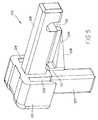
- FIG. 4 shows a perspective view of an corner element in accordance with the present invention.
- FIG. 5 shows another perspective view of the corner element of FIG. 4.
- FIG. 6 shows a side view of the corner element of FIG. 4.
- FIG. 7 shows a bottom view of the corner element of FIG. 4.
- FIG. 8 shows a perspective view of the x-ray cassette with the upper panel removed to show the arrangement of the corner element relative to the storage phosphor assembly contained within the shell of the x-ray cassette.
-
- The following is a detailed description of the preferred embodiments of the invention, reference being made to the drawings in which the same reference numerals identify the same elements of structure in each of the several figures.
- Figures 1-3 show a
storage phosphor cassette 10 in accordance with the present invention.Cassette 10 includes ashell 12 comprising anupper panel 14, alower panel 16, afirst side member 18, asecond side member 20, and afront end member 22. Upper andlower panels First side member 18,second side member 20, andfront end member 22 join upper andlower panels open end 24. -
Cassette 10 further includes astorage phosphor assembly 26 having aback end member 28, aninsert plate 30 having an upper face, and astorage phosphor 32 disposed on the upper face ofinsert plate 30. The front end ofinsert plate 30 includescorners -
Storage phosphor assembly 26 is removably contained within the cavity ofshell 12 such thatback end member 28 ofstorage phosphor assembly 26 closes offopen end 24 ofshell 12, thereby providing a light-tight enclosure forstorage phosphor 32. -
Back end member 28 ofstorage phosphor assembly 26 includesend portions second side members corner structure end portions Corner structures second side members second side members End portions respective corner structures cassette 10 be dropped and a force exerted on eithercorner structure storage phosphor assembly 26, forcingassembly 26 intoshell 12. - To join
first side member 18,second side member 20, andfront end member 22 with upper andlower panels corner element 100 is employed. As illustrated in Figures 1 and 2, twocorner elements 100 are employed, one at each end offront end member 22, to form two corners ofcassette 10.Corner element 100 is more particularly shown in Figures 4-8.Corner element 100 includes acorner portion 101, anupper corner channel 102, alower corner channel 104, afirst leg 105, aninclined element 106, and asecond leg 107. -
Corner portion 101 forms a corner section ofcassette 10. -
Upper corner channel 102 is adapted to receive a corner ofupper panel 14.Lower corner channel 104 is adapted to receive a corner oflower panel 16. As best illustrated in Figures 4, 5, and 7, upper and lower corner channels 102,104 are configured as parallel slots so as to mate with upper andlower panels -
First leg 105 is adapted to mate with eitherfirst side member 18 orsecond side member 20.Second leg 107 is adapted to mate withfront end member 22. As illustrated in Figures 4-8, first and second leg 105,107 are configured to be inserted intomembers - An
inclined element 106 is integrally formed withfirst leg 105. As illustrated,incline element 106 is spaced from upper and lower corner channels 102,104. As shown, upper and lower channels 102,104 are parallel, andfirst leg 105 is perpendicular tosecond leg 107. Inclinedelement 106 includes aface 108 forming an acute angle relative tofirst leg 105, with the taper ofinclined element 106 directed towardsecond leg 107. That is,inclined element 106 is tapered from afirst end 109 to asecond end 110, wherein the taper atsecond end 110 has a higher elevation. An acute angle in the range of between about 5 degrees to about 45 degrees has been found to be suitable. - When
corner element 100 joins upper andlower panels shell 12 therebetween,inclined element 106 is configured to be disposed within the cavity ofshell 12. This is best illustrated in Figure 8. As such, whenstorage phosphor assembly 26 is contained within the cavity ofshell 12,front corners inclined element 106 so thatfront corners inclined element 106 during insertion ofstorage phosphor assembly 26. As such,inclined element 106 acts as a guide portion for the insertion ofstorage phosphor 26 intoshell 12, and further acts as a shock absorber forfront corners cassette 10 be dropped or roughly handled,inclined element 106 provides a bumper or shock absorber for corner edges 68,70. - As shown in Figure 4, face 108 of
inclined element 106 atsecond end 110 preferably has a dimension D which is greater than a width W offirst leg 105. Such a feature assists in the light integrity ofcassette 10. That is, should there exist an opening at a butt joint, in the extrusion interface betweenmembers lower panels corner element 100, the increased dimension offace 108 will form a labyrinth, thereby assisting in the light-tightness of the cassette. Such a labyrinth is formed whencorner element 100 seats securely withmembers - Referring again to Figures 4-8, a
light shielding member 111 disposed atsecond end 110 ofinclined element 106 further assists in the light-tightness ofcassette 10. Whencorner element 100 seats securely withmembers light shielding member 111 abutsside member light shielding member 111 forms a labyrinth, thereby further assisting in the light-tightness of the cassette. -
First leg 105 may optionally include arecess 112 to permit the mechanical fastening of the elements of the x-ray cassette, for example, first and/orsecond side members lower panels -
Corner channel 100 may be comprised of an opaque thermoplastic material, thermosetting material, elastomeric material, thermoplastic elastomer, polymeric material, metal, or a composite material, including polypropylene or polyurethane. Preferably, the material comprisingcorner channel 100 is rigid yet provides for shock absorption shouldcassette 10 be dropped on its corner.
Claims (8)
- A corner element for an x-ray cassette, the x-ray cassette having (i) an upper and lower panel, (ii) a first member joining the upper and lower panels to define a cavity therebetween, and (iii) a storage phosphor assembly adapted to be removably contained within the cavity, the corner element comprising:an upper and lower corner channel for receiving, respectively, the upper and lower panels; anda first leg adapted to mate with the first member and having an inclined element integrally formed therewith, the storage phosphor assembly being disposed adjacent to the inclined element when contained within the cavity.
- The corner element of Claim 1, further comprising a second leg adapted to mate with a second member of the x-ray cassette, the second leg being perpendicular to the first leg.
- The corner element of Claim 1, wherein the upper and lower corner channels are parallel.
- The corner element of Claim 1, wherein the upper and lower corner channels are spaced from the inclined element.
- The corner element of Claim 1, wherein the inclined element forms an acute angle relative to the first leg.
- The corner element of Claim 1, further comprising a light shielding element disposed at one end of the inclined element.
- An x-ray cassette, comprising:a shell comprising an upper and lower panel, a first and second side member, and a front end member, the first and second side members and front end member joining the upper and lower panels to define a cavity;a storage phosphor assembly adapted to be removably contained within the cavity; anda first corner element comprising:(a) an upper and lower corner channel for receiving, respectively, the upper and lower panels, the upper corner channel being parallel to the lower corner channels;(b) a first leg adapted to mate with the first side member, the first leg having an inclined element integrally formed therewith which is disposed adjacent to the storage phosphor assembly when the storage phosphor assembly is contained within the cavity, the inclined element forming an acute angle relative to the first leg; and(c) a second leg adapted to mate with a front end member of the x-ray cassette, the second leg being perpendicular to the first leg.
- The x-ray cassette of Claim 7, further comprising a second corner element comprising:(a) an upper and lower corner channel for receiving, respectively, the upper and lower panels, the upper corner channel being parallel to the lower corner channels;(b) a third leg adapted to mate with the second side member, the third leg having an inclined element integrally formed therewith which is disposed adjacent to the storage phosphor assembly when the storage phosphor assembly is contained within the cavity, the inclined element forming an acute angle relative to the third leg; and(c) a fourth leg adapted to mate with the front end member of the x-ray cassette, the fourth leg being perpendicular to the third leg.
Applications Claiming Priority (2)
| Application Number | Priority Date | Filing Date | Title |
|---|---|---|---|
| US896735 | 2001-06-29 | ||
| US09/896,735 US6571952B2 (en) | 2001-06-29 | 2001-06-29 | Storage phosphor cassette having a corner element |
Publications (2)
| Publication Number | Publication Date |
|---|---|
| EP1271230A1 true EP1271230A1 (en) | 2003-01-02 |
| EP1271230B1 EP1271230B1 (en) | 2004-02-25 |
Family
ID=25406743
Family Applications (1)
| Application Number | Title | Priority Date | Filing Date |
|---|---|---|---|
| EP02077370A Expired - Lifetime EP1271230B1 (en) | 2001-06-29 | 2002-06-17 | Storage phosphor cassette with shock absorbing corner elements |
Country Status (4)
| Country | Link |
|---|---|
| US (1) | US6571952B2 (en) |
| EP (1) | EP1271230B1 (en) |
| JP (1) | JP2003066550A (en) |
| DE (1) | DE60200230T2 (en) |
Families Citing this family (1)
| Publication number | Priority date | Publication date | Assignee | Title |
|---|---|---|---|---|
| USD1095263S1 (en) * | 2023-02-21 | 2025-09-30 | DRTECH Corporation | Radiation detector |
Citations (3)
| Publication number | Priority date | Publication date | Assignee | Title |
|---|---|---|---|---|
| EP0075785A2 (en) * | 1981-09-25 | 1983-04-06 | Agfa-Gevaert AG | X-ray film cassette |
| JPS61192638A (en) * | 1985-02-20 | 1986-08-27 | Toshiba Corp | Recording medium material container |
| JPH0736130A (en) * | 1993-07-16 | 1995-02-07 | Fuji Photo Film Co Ltd | Cassette for radiation picture converting panel |
Family Cites Families (10)
| Publication number | Priority date | Publication date | Assignee | Title |
|---|---|---|---|---|
| JPS6166338U (en) * | 1984-10-04 | 1986-05-07 | ||
| US4697902A (en) | 1985-02-20 | 1987-10-06 | Kabushiki Kaisha Toshiba | Device for containing a radiation recording medium |
| DE3701293A1 (en) * | 1986-10-04 | 1988-04-21 | Master S Art Gmbh | Stackable corner protector |
| DE3900565A1 (en) * | 1989-01-11 | 1990-07-12 | Schueco Int Gmbh & Co | EDGE PROTECTION FRAME FOR PANEL-SHAPED COMPONENTS |
| US5101423A (en) | 1989-02-15 | 1992-03-31 | Kabushiki Kaisha Okamoto Seisakusho | X-ray cassette |
| EP0522317A1 (en) * | 1991-07-11 | 1993-01-13 | Eastman Kodak Company | Cassette for x-ray storage phosphor plate |
| EP0824471B1 (en) * | 1995-04-21 | 1999-08-18 | Storopack Hans Reichenecker Gmbh + Co. | Corner-protection pad |
| US5869839A (en) | 1997-05-23 | 1999-02-09 | Eastman Kodak Company | Storage phosphor cassette with enhanced features |
| US5861631A (en) | 1997-05-23 | 1999-01-19 | Eastman Kodak Company | Storage phosphor cassette with improved durability |
| US5943390A (en) | 1997-09-30 | 1999-08-24 | Eastman Kodak Company | Storage phosphor cassette with reduced weight and cost |
-
2001
- 2001-06-29 US US09/896,735 patent/US6571952B2/en not_active Expired - Lifetime
-
2002
- 2002-06-14 JP JP2002174284A patent/JP2003066550A/en active Pending
- 2002-06-17 EP EP02077370A patent/EP1271230B1/en not_active Expired - Lifetime
- 2002-06-17 DE DE60200230T patent/DE60200230T2/en not_active Expired - Fee Related
Patent Citations (3)
| Publication number | Priority date | Publication date | Assignee | Title |
|---|---|---|---|---|
| EP0075785A2 (en) * | 1981-09-25 | 1983-04-06 | Agfa-Gevaert AG | X-ray film cassette |
| JPS61192638A (en) * | 1985-02-20 | 1986-08-27 | Toshiba Corp | Recording medium material container |
| JPH0736130A (en) * | 1993-07-16 | 1995-02-07 | Fuji Photo Film Co Ltd | Cassette for radiation picture converting panel |
Non-Patent Citations (2)
| Title |
|---|
| PATENT ABSTRACTS OF JAPAN vol. 011, no. 016 (M - 554) 16 January 1987 (1987-01-16) * |
| PATENT ABSTRACTS OF JAPAN vol. 1995, no. 05 30 June 1995 (1995-06-30) * |
Also Published As
| Publication number | Publication date |
|---|---|
| EP1271230B1 (en) | 2004-02-25 |
| DE60200230D1 (en) | 2004-04-01 |
| JP2003066550A (en) | 2003-03-05 |
| US6571952B2 (en) | 2003-06-03 |
| US20030000861A1 (en) | 2003-01-02 |
| DE60200230T2 (en) | 2004-12-02 |
Similar Documents
| Publication | Publication Date | Title |
|---|---|---|
| US5276333A (en) | X-ray cassette having removable photographic element | |
| WO1997038917A1 (en) | Flexible cassette for holding storage phosphor screen | |
| EP0158942A1 (en) | Cassette for stimulable phosphor sheet | |
| US5869839A (en) | Storage phosphor cassette with enhanced features | |
| EP0905715A1 (en) | Storage phosphor cassette with reduced weight and cost | |
| EP1271232B1 (en) | Storage phosphor cassette | |
| US4876706A (en) | Sheet film package | |
| JPH0221574B2 (en) | ||
| EP1271230B1 (en) | Storage phosphor cassette with shock absorbing corner elements | |
| US5861631A (en) | Storage phosphor cassette with improved durability | |
| US6734441B2 (en) | Computed radiography cassette for mammography | |
| EP1316844A1 (en) | Computed radiography cassette with x-ray transmissive edges | |
| EP0632319A1 (en) | Film cassette | |
| US6777691B2 (en) | Storage phosphor cassette | |
| US20030001106A1 (en) | Storage phosphor cassette | |
| US6072188A (en) | Radiation image information recording and reproducing system | |
| JPS63174253A (en) | Electron microscope | |
| EP0675393A2 (en) | Photographic film packet and light locking element | |
| JPS62245246A (en) | Package for sheet film | |
| US7087909B2 (en) | Storage phosphor cassette | |
| EP0140374A2 (en) | High-speed image recording apparatus using stimulable phosphor sheets and lighttight envelope used for same | |
| JP2004145073A (en) | Radiation image photographing apparatus | |
| JPH0614222Y2 (en) | Film holder for X-ray photography | |
| JP2679993B2 (en) | Package for sheet film | |
| JPS63186238A (en) | Film package |
Legal Events
| Date | Code | Title | Description |
|---|---|---|---|
| PUAI | Public reference made under article 153(3) epc to a published international application that has entered the european phase |
Free format text: ORIGINAL CODE: 0009012 |
|
| AK | Designated contracting states |
Kind code of ref document: A1 Designated state(s): AT BE CH CY DE DK ES FI FR GB GR IE IT LI LU MC NL PT SE TR |
|
| AX | Request for extension of the european patent |
Free format text: AL;LT;LV;MK;RO;SI |
|
| 17P | Request for examination filed |
Effective date: 20030528 |
|
| GRAP | Despatch of communication of intention to grant a patent |
Free format text: ORIGINAL CODE: EPIDOSNIGR1 |
|
| AKX | Designation fees paid |
Designated state(s): DE FR GB |
|
| GRAS | Grant fee paid |
Free format text: ORIGINAL CODE: EPIDOSNIGR3 |
|
| GRAA | (expected) grant |
Free format text: ORIGINAL CODE: 0009210 |
|
| AK | Designated contracting states |
Kind code of ref document: B1 Designated state(s): DE FR GB |
|
| REG | Reference to a national code |
Ref country code: GB Ref legal event code: FG4D |
|
| REG | Reference to a national code |
Ref country code: IE Ref legal event code: FG4D |
|
| REF | Corresponds to: |
Ref document number: 60200230 Country of ref document: DE Date of ref document: 20040401 Kind code of ref document: P |
|
| ET | Fr: translation filed | ||
| PLBE | No opposition filed within time limit |
Free format text: ORIGINAL CODE: 0009261 |
|
| STAA | Information on the status of an ep patent application or granted ep patent |
Free format text: STATUS: NO OPPOSITION FILED WITHIN TIME LIMIT |
|
| 26N | No opposition filed |
Effective date: 20041126 |
|
| REG | Reference to a national code |
Ref country code: IE Ref legal event code: MM4A |
|
| REG | Reference to a national code |
Ref country code: GB Ref legal event code: 732E |
|
| PGFP | Annual fee paid to national office [announced via postgrant information from national office to epo] |
Ref country code: DE Payment date: 20080630 Year of fee payment: 7 |
|
| PGFP | Annual fee paid to national office [announced via postgrant information from national office to epo] |
Ref country code: GB Payment date: 20080506 Year of fee payment: 7 |
|
| REG | Reference to a national code |
Ref country code: FR Ref legal event code: TP |
|
| GBPC | Gb: european patent ceased through non-payment of renewal fee |
Effective date: 20090617 |
|
| REG | Reference to a national code |
Ref country code: FR Ref legal event code: ST Effective date: 20100226 |
|
| PG25 | Lapsed in a contracting state [announced via postgrant information from national office to epo] |
Ref country code: FR Free format text: LAPSE BECAUSE OF NON-PAYMENT OF DUE FEES Effective date: 20090630 |
|
| PGFP | Annual fee paid to national office [announced via postgrant information from national office to epo] |
Ref country code: FR Payment date: 20080424 Year of fee payment: 7 |
|
| PG25 | Lapsed in a contracting state [announced via postgrant information from national office to epo] |
Ref country code: GB Free format text: LAPSE BECAUSE OF NON-PAYMENT OF DUE FEES Effective date: 20090617 |
|
| PG25 | Lapsed in a contracting state [announced via postgrant information from national office to epo] |
Ref country code: DE Free format text: LAPSE BECAUSE OF NON-PAYMENT OF DUE FEES Effective date: 20100101 |