EP1271194A2 - Optical bandpass filter using long period gratings - Google Patents
Optical bandpass filter using long period gratings Download PDFInfo
- Publication number
- EP1271194A2 EP1271194A2 EP02014330A EP02014330A EP1271194A2 EP 1271194 A2 EP1271194 A2 EP 1271194A2 EP 02014330 A EP02014330 A EP 02014330A EP 02014330 A EP02014330 A EP 02014330A EP 1271194 A2 EP1271194 A2 EP 1271194A2
- Authority
- EP
- European Patent Office
- Prior art keywords
- optical
- mode
- lpg
- fiber
- waveguide
- Prior art date
- Legal status (The legal status is an assumption and is not a legal conclusion. Google has not performed a legal analysis and makes no representation as to the accuracy of the status listed.)
- Granted
Links
Images


Classifications
-
- G—PHYSICS
- G02—OPTICS
- G02B—OPTICAL ELEMENTS, SYSTEMS OR APPARATUS
- G02B6/00—Light guides; Structural details of arrangements comprising light guides and other optical elements, e.g. couplings
- G02B6/02—Optical fibres with cladding with or without a coating
- G02B6/02057—Optical fibres with cladding with or without a coating comprising gratings
- G02B6/02076—Refractive index modulation gratings, e.g. Bragg gratings
- G02B6/0208—Refractive index modulation gratings, e.g. Bragg gratings characterised by their structure, wavelength response
- G02B6/02085—Refractive index modulation gratings, e.g. Bragg gratings characterised by their structure, wavelength response characterised by the grating profile, e.g. chirped, apodised, tilted, helical
- G02B6/02095—Long period gratings, i.e. transmission gratings coupling light between core and cladding modes
-
- G—PHYSICS
- G02—OPTICS
- G02B—OPTICAL ELEMENTS, SYSTEMS OR APPARATUS
- G02B6/00—Light guides; Structural details of arrangements comprising light guides and other optical elements, e.g. couplings
- G02B6/10—Light guides; Structural details of arrangements comprising light guides and other optical elements, e.g. couplings of the optical waveguide type
- G02B6/12—Light guides; Structural details of arrangements comprising light guides and other optical elements, e.g. couplings of the optical waveguide type of the integrated circuit kind
- G02B6/12007—Light guides; Structural details of arrangements comprising light guides and other optical elements, e.g. couplings of the optical waveguide type of the integrated circuit kind forming wavelength selective elements, e.g. multiplexer, demultiplexer
-
- G—PHYSICS
- G02—OPTICS
- G02B—OPTICAL ELEMENTS, SYSTEMS OR APPARATUS
- G02B6/00—Light guides; Structural details of arrangements comprising light guides and other optical elements, e.g. couplings
- G02B6/24—Coupling light guides
- G02B6/255—Splicing of light guides, e.g. by fusion or bonding
-
- G—PHYSICS
- G02—OPTICS
- G02B—OPTICAL ELEMENTS, SYSTEMS OR APPARATUS
- G02B6/00—Light guides; Structural details of arrangements comprising light guides and other optical elements, e.g. couplings
- G02B6/24—Coupling light guides
- G02B6/26—Optical coupling means
- G02B6/28—Optical coupling means having data bus means, i.e. plural waveguides interconnected and providing an inherently bidirectional system by mixing and splitting signals
- G02B6/293—Optical coupling means having data bus means, i.e. plural waveguides interconnected and providing an inherently bidirectional system by mixing and splitting signals with wavelength selective means
- G02B6/29304—Optical coupling means having data bus means, i.e. plural waveguides interconnected and providing an inherently bidirectional system by mixing and splitting signals with wavelength selective means operating by diffraction, e.g. grating
- G02B6/29316—Light guides comprising a diffractive element, e.g. grating in or on the light guide such that diffracted light is confined in the light guide
- G02B6/29317—Light guides of the optical fibre type
- G02B6/29319—With a cascade of diffractive elements or of diffraction operations
-
- G—PHYSICS
- G02—OPTICS
- G02B—OPTICAL ELEMENTS, SYSTEMS OR APPARATUS
- G02B6/00—Light guides; Structural details of arrangements comprising light guides and other optical elements, e.g. couplings
- G02B6/24—Coupling light guides
- G02B6/26—Optical coupling means
- G02B6/28—Optical coupling means having data bus means, i.e. plural waveguides interconnected and providing an inherently bidirectional system by mixing and splitting signals
- G02B6/293—Optical coupling means having data bus means, i.e. plural waveguides interconnected and providing an inherently bidirectional system by mixing and splitting signals with wavelength selective means
- G02B6/29379—Optical coupling means having data bus means, i.e. plural waveguides interconnected and providing an inherently bidirectional system by mixing and splitting signals with wavelength selective means characterised by the function or use of the complete device
- G02B6/29389—Bandpass filtering, e.g. 1x1 device rejecting or passing certain wavelengths
-
- G—PHYSICS
- G02—OPTICS
- G02B—OPTICAL ELEMENTS, SYSTEMS OR APPARATUS
- G02B6/00—Light guides; Structural details of arrangements comprising light guides and other optical elements, e.g. couplings
- G02B6/24—Coupling light guides
- G02B6/42—Coupling light guides with opto-electronic elements
- G02B6/4201—Packages, e.g. shape, construction, internal or external details
- G02B6/4204—Packages, e.g. shape, construction, internal or external details the coupling comprising intermediate optical elements, e.g. lenses, holograms
- G02B6/4215—Packages, e.g. shape, construction, internal or external details the coupling comprising intermediate optical elements, e.g. lenses, holograms the intermediate optical elements being wavelength selective optical elements, e.g. variable wavelength optical modules or wavelength lockers
-
- H—ELECTRICITY
- H01—ELECTRIC ELEMENTS
- H01S—DEVICES USING THE PROCESS OF LIGHT AMPLIFICATION BY STIMULATED EMISSION OF RADIATION [LASER] TO AMPLIFY OR GENERATE LIGHT; DEVICES USING STIMULATED EMISSION OF ELECTROMAGNETIC RADIATION IN WAVE RANGES OTHER THAN OPTICAL
- H01S3/00—Lasers, i.e. devices using stimulated emission of electromagnetic radiation in the infrared, visible or ultraviolet wave range
- H01S3/05—Construction or shape of optical resonators; Accommodation of active medium therein; Shape of active medium
- H01S3/06—Construction or shape of active medium
- H01S3/063—Waveguide lasers, i.e. whereby the dimensions of the waveguide are of the order of the light wavelength
- H01S3/067—Fibre lasers
- H01S3/0675—Resonators including a grating structure, e.g. distributed Bragg reflectors [DBR] or distributed feedback [DFB] fibre lasers
-
- G—PHYSICS
- G02—OPTICS
- G02B—OPTICAL ELEMENTS, SYSTEMS OR APPARATUS
- G02B6/00—Light guides; Structural details of arrangements comprising light guides and other optical elements, e.g. couplings
- G02B6/10—Light guides; Structural details of arrangements comprising light guides and other optical elements, e.g. couplings of the optical waveguide type
- G02B6/12—Light guides; Structural details of arrangements comprising light guides and other optical elements, e.g. couplings of the optical waveguide type of the integrated circuit kind
- G02B2006/12083—Constructional arrangements
- G02B2006/12107—Grating
-
- G—PHYSICS
- G02—OPTICS
- G02B—OPTICAL ELEMENTS, SYSTEMS OR APPARATUS
- G02B6/00—Light guides; Structural details of arrangements comprising light guides and other optical elements, e.g. couplings
- G02B6/10—Light guides; Structural details of arrangements comprising light guides and other optical elements, e.g. couplings of the optical waveguide type
- G02B6/14—Mode converters
-
- H—ELECTRICITY
- H01—ELECTRIC ELEMENTS
- H01S—DEVICES USING THE PROCESS OF LIGHT AMPLIFICATION BY STIMULATED EMISSION OF RADIATION [LASER] TO AMPLIFY OR GENERATE LIGHT; DEVICES USING STIMULATED EMISSION OF ELECTROMAGNETIC RADIATION IN WAVE RANGES OTHER THAN OPTICAL
- H01S3/00—Lasers, i.e. devices using stimulated emission of electromagnetic radiation in the infrared, visible or ultraviolet wave range
- H01S3/05—Construction or shape of optical resonators; Accommodation of active medium therein; Shape of active medium
- H01S3/08—Construction or shape of optical resonators or components thereof
- H01S3/08018—Mode suppression
- H01S3/08022—Longitudinal modes
- H01S3/08027—Longitudinal modes by a filter, e.g. a Fabry-Perot filter is used for wavelength setting
-
- H—ELECTRICITY
- H01—ELECTRIC ELEMENTS
- H01S—DEVICES USING THE PROCESS OF LIGHT AMPLIFICATION BY STIMULATED EMISSION OF RADIATION [LASER] TO AMPLIFY OR GENERATE LIGHT; DEVICES USING STIMULATED EMISSION OF ELECTROMAGNETIC RADIATION IN WAVE RANGES OTHER THAN OPTICAL
- H01S3/00—Lasers, i.e. devices using stimulated emission of electromagnetic radiation in the infrared, visible or ultraviolet wave range
- H01S3/10—Controlling the intensity, frequency, phase, polarisation or direction of the emitted radiation, e.g. switching, gating, modulating or demodulating
- H01S3/13—Stabilisation of laser output parameters, e.g. frequency or amplitude
- H01S3/139—Stabilisation of laser output parameters, e.g. frequency or amplitude by controlling the mutual position or the reflecting properties of the reflectors of the cavity, e.g. by controlling the cavity length
Definitions
- This invention relates to optical filters, and more particularly to optical bandpass filters with low loss.
- Optical bandpass filers transmit light over a pre-determined band of wavelengths while rejecting, by absorption, radiation or scattering, all other wavelengths.
- Such filters are useful in laser cavities or optical communications systems. For example, they may be used to constrain the wavelength of operation of a laser, when deployed inside or outside the laser cavity.
- optical communications systems they can be used at the input of an optical receiver to separate unwanted light such as spontaneous emission noise outside the wavelength band of the signal. See D.M. Shamoon, J.M.H. Elmirghani, R. A. Cryan, "Characterisation of optically preamplified receivers with fibre Bragg grating optical fibers", IEEE Colloquium on Optical Fiber Gratings, March 1996 .
- Optical regenerators based on self-phase modulation require extracting a predetermined wavelength band from a broad spectrum of light.
- Fiber Bragg gratings may be used in the reflection mode with a circulator, or in the transmission mode, to select a narrow wavelength band. See Xu, M. G.; Alavie, A. T. ; Maaskant, R.; Ohn, M. M.; "Tunable fiber bandpass filter based on a linearly chirped fiber Bragg grating for wavelength demultiplexing", Electron Lett ., 32 , pp. 1918-1919 (1996). Operation in the reflection mode requires addition of a circulator in the transmission line - this increases cost, loss and complexity for the device.
- Bragg gratings used either in transmission or reflection
- filters can be highly dispersive, which gives rise to pulse shape distortions.
- thin film dielectric filters may also be used as bandpass filters (see: U.S. Patent No. 5,615,289), but in addition to their dispersive nature (similar to Bragg gratings) they suffer from the additional drawbacks of being free-space devices.
- light needs to be coupled into fiber pigtails for use in such fiber-optic systems. This increases loss, cost and complexity.
- An alternative technique for making bandpass filters uses two identical long-period fiber gratings (LPGs) that are spliced in series in the fiber-optic transmission line, with a core block between them.
- LPGs long-period fiber gratings
- the first long period grating converts a narrow wavelength-band of core-mode light into a cladding mode
- the second identical grating couples the cladding-mode light back into the core mode.
- the core block between the two LPGs attenuates or scatters any light that was not converted into the cladding mode.
- drawbacks associated with this device - (1) the core block simultaneously attenuates light in all the modes, thus the device is inherently lossy.
- LPGs are used in a new configuration to provide in-line band pass filtering of optical signals in an optical system.
- the optical system is an optical fiber system.
- two dissimilar LPGs are installed in serially cascaded optical waveguides of the transmission line.
- the signal light In the first waveguide of the filter, the signal light is initially transmitted in the fundamental, or LP 01 mode.
- the first LPG converts the signal light, over a broad wavelength range, into a higher order mode (HOM) of the first optical waveguide.
- HOM higher order mode
- the conversion is achieved using a broadband LPG that provide strong mode conversion over a broad spectrum. See. S. Ramachandran, M. F. Yan, L. C. Cowsar, A. C. Carra, P.
- the broadband LPG is designated BB-LPG.
- the BB-LPG operates by exciting either a core guided HOM or a cladding guided HOM of the first optical waveguide.
- the mode-converted signal, with mode LP m,n is then coupled to the second optical waveguide, the second waveguide having transmission characteristics different from those of the first optical waveguide.
- the second waveguide strongly couples to the LP m,n mode, because the second LPG, which may be a conventional LPG, provides a strong narrow band coupling between LP m,n and LP 01 modes of the second optical waveguide.
- the second LPG is referred to here as a narrow band LPG (NB-LPG).
- Light entering the dual LPG filter first encounters the BB-LPG where more than 99% of the signal is converted to a LP m,n mode over a broad wavelength range.
- the converted signal encounters the NB-LPG, the signal over a selected narrow band of wavelengths accepted by the NB-LPG is converted back to the LP 01 mode of the second waveguide.
- the selected narrow band in the LP 01 mode propagates efficiently over the remainder of the optical waveguide transmission path; i.e., the remainder of the second waveguide.
- the mode distribution profiles of the LP m,n mode excited in the BB -LPG and the LP m,n converted in the NB-LPG do not have to match, as long as the order of the modes (m and n) are the same.
- the BB -LPG and the NB-LPG may comprise separate waveguide sections, or may be formed in same length of waveguide.
- the waveguides are preferably optical fibers. If the LPGs comprise separate optical fibers spliced together the signal adiabatically couples at the splice since the mode shapes are the same.
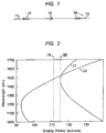
- the filter comprises a first fiber section 11 with a BB-LPG 12, a second fiber section 13, with a NB-LPG 14, and a splice 15 connecting the two fiber sections together.
- the splice 15 adiabatically converts the HOM of fiber 11 to the HOM of fiber 13.
- the BB-LPG 12 has a grating period selected for broad-band mode conversion
- the NB-LPG 14 has a different grating period chosen for narrow band, i.e., bandpass, mode conversion.
- the choice of grating periods is illustrated in Fig. 2.
- Curve 21 represents the phase-matching relationship of a fiber that yields a BB-LPG at about 1470 nm.
- a unique feature of the curve 21 is the turn-around point (TAP) in the phase matching relationship.
- TAP turn-around point
- a vertical line 22 is tangent to the phase-matching curve 21. If a grating period has the value corresponding to the tangent line 22, a broad range of wavelengths approximately satisfy the phase-matching relationship. For wavelengths in this range, a BB-LPG results, because the wavelengths are at or close to resonance near the TAP.
- a BB-LPG with a period of 115 microns (line 22) yields a BB-LPG at about 1470 nm.
- Curve 23 corresponds to the phase-matching relationship of a LPG in a second fiber. From curve 23, one sees that the LPG yields a NB-LPG for any wavelength greater than about 1300 nm. That is, for wavelengths greater than 1300 nm, a vertical line corresponding to a selected grating period is never tangent to the phase-matching curve 23. Thus, there is not a broad range of wavelengths that approximately satisfy the phase-matching relationship. For example, line 24, intersects the phase-matching relationship at only one wavelength.
- curve 23 represents a fiber with the same index profile as that represented by curve 21, but the fiber associated with curve 23 is drawn to a diameter that is 80% of the original diameter of the fiber associated with curve 21.
- Dimensionally scaling a fiber in this manner shifts the TAP of the fiber.
- a fiber that yields a BB-LPG when drawn to one diameter yields a NB-LPG when drawn to a different diameter.
- Dimensionally scaling is one of several ways to shift or adjust the TAP of the fiber. The same objective may be realized by inducing a constant index change in the fiber, or by etching the outer diameter of the cladding. While the former technique will result in shifting the TAP of both a cladding mode as well as a core-guided mode, the latter will be useful when the HOM employed for the bandpass filter is a cladding mode.
- An LPG written at the corresponding grating period (112.5 ⁇ m) converts the incoming LP 01 mode into the LP 02 mode over the entire C-band.
- the length of this grating is 1 cm, with an index perturbation of 5 x 10 -3 . This illustrates that more than 99%(>20dB) of light is converted over a spectral range between 1527 nm and 1571 nm.
- the wavelength range of the BB-LPG may be controlled by suitably designing a fiber with different dispersion properties for the fundamental mode and the HOM.
- ⁇ D is the difference in dispersion between the two modes that are being coupled by the BB-LPG
- L is the length of the grating
- ⁇ res is the resonant wavelength (where maximum coupling occurs)
- c is the velocity of light in a vacuum
- A is a constant determined by the maximum coupling strength of the grating.
- the wavelength range in a typical BB-LPG may range from 40 to 100 nm.
- Fiber section 13 is a few-mode fiber similar to fiber 11, but is drawn to an OD of 112 ⁇ m.
- the spectrum of an NB-LPG in this fiber is shown by curve 32 in Fig. 3. This spectrum is for a 5.7 cm long uniform LPG with a grating period of 120 ⁇ m, and an index perturbation of 1 x 10 -4 .
- the 3 dB bandwidth is 7 nm and provides 99.6% (24 dB) mode-conversion at the resonant wavelength of 1555 nm.
- the LPG spectra may be tailored in bandwidth by modifying the dispersive properties of the fiber, or the physical parameters of the grating.
- chirping the period of the grating, or apodizing the index perturbations of the gratings can yield a multitude of spectral shapes (e.g. rectangular, Gaussian, etc.).
- the device functions as follows.
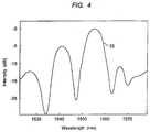
- LP 02 mode light traverses splice 15, that splices fiber section 11 to fiber section 13, the LP 02 mode light of fiber 11 is adiabatically converted into the LP 02 mode of fiber 13. Then, the NB-LPG 14 selects a desired narrow portion of the spectrum and converts that back into the LP 01 mode. This results in a bandpass filter, with properties shown by curve 35 in Fig. 4.
- the device illustrated in Fig. 1 provides a general platform for building band-selection as opposed to band-rejection filters with LPGs.
- the first mode-converter, BB-LPG 12 only serves as a device that provides a spatially modified input for NB-LPG 14, and does not define the spectral characteristics of the bandpass filter.
- the spectrum of the filter is defined by the inverted spectrum of the NB-LPG 14.
- several NB-LPG may be added in series.
- the NB-LPG may be designed to possess multiple narrowband resonances. This enables the prospect of spectral shaping in the band-pass configuration by varying the spectral properties of one or more NB-LPG 14.
- the device just described has an advantage over conventional filters using LPGs in that no core-blocking element is used. This avoids the loss inherent in devices with that configuration.
- the transmission path between the BB-LPG and the NB-LPG functions adiabatically.
- the transmission path coupling the LPGs does not include an active attenuation element, i.e. an element that has an intended and deliberate function of attenuating light. It is not intended that a conventional splice, which is designed for minimum light attenuation as is not, in this context, an active attenuation element.
- the splice element 15 in Fig. 1 adiabatically transforms the HOM of fiber 11 (after traversing the NB-LPG) into a HOM of fiber 13. This may be achieved by inducing a heat profile along the splice and/or tapering one fiber with respect to the other to ensure that the two HOMs couple efficiently.
- the two fibers 11 and 13 are shown with a physical splice joining them, i.e. fibers 11 and 13 are separate fibers.
- the physical splice 15, and the attendant loss in that splice may be avoided by making a single fiber with two distinct transmission characteristics. For example, the diameter of the fiber may be made to vary longitudinally along the fiber length, i.e.
- the functional operation of splice 15 is the important aspect, and may be defined as a means for effecting a change from a HOM with one characteristic to a corresponding HOM with a different characteristic.
- the filter of the invention may also be tuned by inducing a shift in the phase-matching curve for the NB-LPG (curve 23 of Fig. 2).
- doping the cladding of the fiber, or coating the outside cladding of the fiber with an electro-optic or non-linear optic material allows electrical or optical control of the resonant wavelength of the bandpass filter.
- the bandpass filter of the invention may be used in a variety of systems.
- a variety of laser devices can be tuned using the bandpass filter of the invention as an intracavity element.
- the two narrow band reflectors are replaced by two broadband reflectors (one high and one weak) with the bandpass filter of the invention in the cavity.
- the lasing wavelength may be adjusted by tuning the filter. Multiple lasing wavelengths can be produced by having one or more NB-LPGS in the bandpass filter that have multiple resonances.
- Fig. 5 An illustration of this generalized form of laser is shown in Fig. 5, where the gain fiber is shown at 38, high reflector at 39, weak reflector at 41, input signal at 43, laser pump at 44, and WDM for combining signal and pump at 45.
- the bandpass filter of the invention shown generally ar 46, and comprising BB-LPG 47, NB-LPG 48, and splice 49, is placed inside the laser cavity as shown.
- a specific form of laser, a cascaded Raman fiber laser, is especially adapted for use with the filter of the invention.
- These devices can be made to operate at multiple wavelengths by employing multiple sets of Bragg gratings that comprise narrowband high-reflectors and output couplers/weak reflectors. These pairs of Bragg gratings define laser cavities, and the resonant wavelength of the narrowband grating defines the lasing wavelength.
- the Raman resonator 51 comprises fiber 52 and gratings 53, 54.
- the resonator is bounded on both sides by a narrow band grating.
- the resonator is bounded by broadband high-reflector 48, and weak reflector 49 gratings.
- the resonant wavelength is controlled by a bandpass filter 56 of the invention.
- the bandpass filter 56 comprises, as described earlier, BB-LPG 57, NB-LPG 58, and splice 59. Tuning is achieved by tuning the NB-LPG of the bandpass filter.
- LPGs and therefore the LPG bandpass filters
- LPG bandpass filters are widely tunable by methods described earlier
- a swept wavelength source useful in Raman amplified optical communications systems, would be easily realizable.
- multiple NB-LPG 58 may be added in series to provide simultaneous tunable operation of the device over several lasing wavelengths.
- the bandpass filters of the invention are also well adapted for use with self-phase modulation (SPM) based optical regenerators. These devices are relatively simple and typically comprise a non-linear fiber associated with a bandpass filter (see US Patent No. 6,141,129). The signal is launched into the non-linear fiber section, thereby inducing SPM in the signal. The effect is to broaden the spectrum of the portions of the signal that exceed a selected intensity value. The bandpass filter then selects a predetermined portion of the broadened spectrum. Ideally the bandpass filter for this application should be tunable to account for temporal changes in the spectrum. It is also desirable that the filter be dispersion-less. These desiderata are satisfied by the bandpass filter of the invention.
- FIG. 7 A schematic representation of an optical regenerator using the bandpass filter of the invention is shown in Fig. 7.
- the non-linear fiber section is shown at 62, and the bandpass filter, comprising BB-LPG 67, NB-LPG 68, and splice 69, is shown generally at 66.
- Pre-amplifiers for optical receivers employ noise filters for removing spontaneous emission noise from the received signal.
- This noise originates from amplifiers along the transmission path.
- the noise is typically over the entire spectral range including the signal wavelength, and substantial sidebands of the signal.
- This background noise degrades the signal-to-noise ratio of the signal to the receiver.
- a bandpass filter could selectively attenuate noise outside the signal wavelength, and therefore improve the optical signal-to-noise ratio, but would be especially effective if the bandpass filter were dispersion-less. That characteristics is provided by the bandpass filter of the invention.
- FIG. 8 An optical pre-amplifier system as just described is shown in Fig. 8, where the optical amplifier 72 is followed by a bandpass filter, shown generally at 76, comprising BB-LPG 77, NB-LPG 78, and splice 79. The filtered signal is then introduced into a receiver, represented in the figure by light sensitive diode 81.
- a bandpass filter shown generally at 76, comprising BB-LPG 77, NB-LPG 78, and splice 79.
- the filtered signal is then introduced into a receiver, represented in the figure by light sensitive diode 81.
- optical fibers for implementing the bandpass filter of the invention.
- Similar devices may be constructed using other forms of waveguides, for example planar waveguides in optical integrated circuit (OIC) devices.
- OIC optical integrated circuit
- the long period gratings described here may be formed by various techniques.
- a common approach is to write the gratings into a Ge doped fiber using UV light.
- other methods may also be used.
- microbend induced LPGs are suitable. These can be realized with acousto-optic gratings, arc-splicer induced periodic microbends, or by pressing the fiber between corrugated blocks that have the required grating periodicity.
Landscapes
- Physics & Mathematics (AREA)
- Optics & Photonics (AREA)
- General Physics & Mathematics (AREA)
- Engineering & Computer Science (AREA)
- Plasma & Fusion (AREA)
- Electromagnetism (AREA)
- Microelectronics & Electronic Packaging (AREA)
- Optical Modulation, Optical Deflection, Nonlinear Optics, Optical Demodulation, Optical Logic Elements (AREA)
- Optical Communication System (AREA)
- Optical Integrated Circuits (AREA)
- Lasers (AREA)
Abstract
Description
Claims (12)
- An optical filter comprising:a. an optical waveguide having a first portion and a second portion,b. a BB-LPG in the first portion of optical waveguide,c. a NB-LPG in the second portion of optical waveguide, andd. a coupler for serially coupling the first portion and the second portion.
- The optical filter of claim 1 wherein the first portion of optical waveguide and the second portion of optical fiber each comprise optical fiber.
- The optical filter of claim 2 wherein the coupler comprises a fiber splice.
- The optical filter of claim 2 wherein the first portion of optical fiber has a diameter different from the diameter of the second portion of optical fiber.
- An optical filter comprising:a. an optical waveguide having a first portion and a second portion, the first and second portions being serially connected,b. a first LPG for converting signal light propagating in mode LP01 into a signal propagating in mode LPm,n,c. an optical coupler configured to transmit a signal light propagating in mode LPm,n in the first portion to LPr,s mode light in the second portion, wherein m = r and n = s,d. a second LPG for converting a selected band Δλ2 of the signal light propagating in mode LPr,s in the second portion to light propagating in mode LP01.
- The optical filter of claim 5, further comprising:a lightwave signaling means for introducing a lightwave signal into the first portion, the introduced lightwave signal having a bandwidth Δλ1 and propagating as mode LP01,
- The optical filter of claim 5 wherein the first portion of optical waveguide and the second portion of optical waveguide each comprise optical fiber.
- The optical filter of claim 7 wherein the first portion of optical waveguide and the second portion of optical waveguide each comprise optical fiber.
- The optical filter of claim 6 wherein the optical coupler comprises a fiber splice.
- The optical filter of claim 2 associated in an optical system comprising a cascaded Raman resonator having a Raman resonator cavity, wherein the optical filter is serailly coupled to the Raman resonator.
- The optical filter of claim 2 associated in an optical system comprising an optical amplifier, wherein the optical filter is serially coupled to the optical amplifier.
- A laser comprising:a. a resonant cavity,b. tuning means in the resonant cavity, the tuning means comprising:i..an optical waveguide having a first portion and a second portion, the first and second portions being serially connectedii. a BB-LPG in the first portion of optical waveguide,iii. a NB-LPG in the second portion of optical waveguide, andiv. a coupler for coupling the first portion and the second portion.
Applications Claiming Priority (4)
| Application Number | Priority Date | Filing Date | Title |
|---|---|---|---|
| US167684P | 1999-11-29 | ||
| US30116401P | 2001-06-27 | 2001-06-27 | |
| US10/167,684 US6845194B2 (en) | 2001-06-27 | 2002-06-11 | Optical bandpass filter using long period gratings |
| US301164P | 2010-02-03 |
Publications (3)
| Publication Number | Publication Date |
|---|---|
| EP1271194A2 true EP1271194A2 (en) | 2003-01-02 |
| EP1271194A3 EP1271194A3 (en) | 2003-11-12 |
| EP1271194B1 EP1271194B1 (en) | 2006-06-07 |
Family
ID=26863385
Family Applications (1)
| Application Number | Title | Priority Date | Filing Date |
|---|---|---|---|
| EP02014330A Expired - Lifetime EP1271194B1 (en) | 2001-06-27 | 2002-06-27 | Optical bandpass filter using long period gratings |
Country Status (3)
| Country | Link |
|---|---|
| US (2) | US6845194B2 (en) |
| EP (1) | EP1271194B1 (en) |
| DE (1) | DE60212003T2 (en) |
Cited By (4)
| Publication number | Priority date | Publication date | Assignee | Title |
|---|---|---|---|---|
| FR2860598A1 (en) * | 2003-10-03 | 2005-04-08 | Cit Alcatel | SUPRESSION OF MODE (S) FOR PROPAGATION OF UNDESIRABLE SIGNALS BEFORE A MODE CONVERTER |
| WO2005053120A1 (en) * | 2003-11-20 | 2005-06-09 | Northrop Grumman Corporation | Long period bragg grating optical signal attenuation |
| WO2011033031A1 (en) * | 2009-09-18 | 2011-03-24 | Ludwig-Maximilians-Universität München | Tunable wavelength light source |
| EP2109789A4 (en) * | 2007-02-05 | 2014-02-19 | Furukawa Electric North Am Inc | Selectively pumping a gain-doped region of an optical fiber |
Families Citing this family (18)
| Publication number | Priority date | Publication date | Assignee | Title |
|---|---|---|---|---|
| AU2002316478A1 (en) * | 2001-07-02 | 2003-01-21 | Ogg Technology Licensing, Llc. | Multi-wavelength optical fiber |
| US20050113996A1 (en) * | 2001-12-21 | 2005-05-26 | Oshkosh Truck Corporation | Ambulance control system and method |
| US20030174956A1 (en) * | 2002-03-13 | 2003-09-18 | Jean-Francois Viens | Polarization insensitive modal field transformer for high index contrast waveguide devices |
| US6983096B2 (en) * | 2003-04-15 | 2006-01-03 | Intel Corporation | Attenuation of cladding modes in optical fibers |
| US6950578B1 (en) | 2004-05-28 | 2005-09-27 | Fitel Usa Corp. | Highly index-sensitive optical devices including long period fiber gratings |
| US7228029B1 (en) * | 2005-09-20 | 2007-06-05 | Furukawa Electric North America Inc. | Short pulse lasers using large mode area fibers and higher order modes |
| US7675950B2 (en) * | 2005-12-05 | 2010-03-09 | Panasonic Corporation | Laser light source device and image display apparatus |
| KR100913366B1 (en) * | 2007-07-18 | 2009-08-20 | 성균관대학교산학협력단 | Optical biosensor using the phenomenon of SPR (Personalized Phenomenon) |
| US8111160B2 (en) * | 2007-07-30 | 2012-02-07 | Lasercard Corporation | Light enabled RFID card |
| US8270786B2 (en) * | 2008-11-21 | 2012-09-18 | Ofs Fitel, Llc | Optical fiber mode couplers |
| WO2010132466A1 (en) * | 2009-05-11 | 2010-11-18 | OFS Fitel LLC, a Delaware Limited Liability Company | Systems and methods for cascaded raman lasting at high power levels |
| US20130194570A1 (en) * | 2012-01-31 | 2013-08-01 | Wei Wu | Apparatus for performing spectroscopy |
| IL221918A (en) * | 2012-09-12 | 2016-11-30 | V-Gen Ltd | Optical isolator |
| CN103869419B (en) * | 2014-03-31 | 2016-08-31 | 武汉光迅科技股份有限公司 | A kind of optical filter being applied to the adjustable reception of TWDM-PON |
| US9634462B2 (en) * | 2014-10-15 | 2017-04-25 | Nlight, Inc. | Slanted FBG for SRS suppression |
| CN104834056B (en) * | 2015-05-12 | 2017-12-29 | 浙江工业大学 | A kind of preparation method of LPFG bandpass and band-rejection filter |
| WO2020139704A1 (en) * | 2018-12-28 | 2020-07-02 | Nlight, Inc. | Optical fiber devices and methods for suppressing stimulated raman scattering (srs) |
| CN110380326B (en) * | 2019-07-29 | 2020-10-23 | 武汉电信器件有限公司 | Optical signal output device and method, and storage medium |
Family Cites Families (19)
| Publication number | Priority date | Publication date | Assignee | Title |
|---|---|---|---|---|
| US5074633A (en) * | 1990-08-03 | 1991-12-24 | At&T Bell Laboratories | Optical communication system comprising a fiber amplifier |
| FR2745641B1 (en) * | 1996-03-01 | 1998-04-10 | Alcatel Submarcom | FILTER OBTAINED BY REGISTERING A BRAGG NETWORK IN AN OPTICAL FIBER |
| US6212310B1 (en) * | 1996-10-22 | 2001-04-03 | Sdl, Inc. | High power fiber gain media system achieved through power scaling via multiplexing |
| US6021240A (en) * | 1997-10-02 | 2000-02-01 | F&S, Inc. | Optical sensor activation device |
| US6058226A (en) * | 1997-10-24 | 2000-05-02 | D-Star Technologies Llc | Optical fiber sensors, tunable filters and modulators using long-period gratings |
| US6084996A (en) * | 1998-04-01 | 2000-07-04 | Lucent Technologies, Inc. | Broadband long-period gratings |
| KR100274075B1 (en) * | 1998-05-09 | 2001-01-15 | 서원석 | Optical fiber grating and optical element using the same |
| JP3149921B2 (en) * | 1998-05-18 | 2001-03-26 | 住友電気工業株式会社 | Optical loss filter and method of manufacturing the same |
| US6317538B1 (en) * | 1998-12-07 | 2001-11-13 | Sumitomo Electric Industries, Ltd. | Optical waveguide device and optical device having long-period grating |
| US6151427A (en) * | 1999-04-20 | 2000-11-21 | The United States Of America As Represented By The National Security Agency | Tunable optic fiber bandpass filter using flexural acoustic waves |
| US6434172B1 (en) * | 1999-08-06 | 2002-08-13 | Fitel Usa Corp. | Article comprising a fiber raman device |
| US20030215185A1 (en) * | 1999-12-06 | 2003-11-20 | Cidra Corporation, | Large diameter optical waveguide having long period grating therein |
| KR100315671B1 (en) * | 1999-12-28 | 2001-11-29 | 윤종용 | Apparatus and method for fabricating multi-period optical fiber grating |
| JP2001255423A (en) * | 2000-03-13 | 2001-09-21 | Furukawa Electric Co Ltd:The | Optical components |
| DE10017946A1 (en) * | 2000-04-11 | 2002-01-17 | Abb Research Ltd | Fiber laser sensor |
| JP2002139629A (en) * | 2000-10-31 | 2002-05-17 | Sumitomo Electric Ind Ltd | Optical loss filter |
| JP2002169028A (en) * | 2000-12-01 | 2002-06-14 | Sumitomo Electric Ind Ltd | Optical loss filter |
| WO2002054631A2 (en) * | 2000-12-30 | 2002-07-11 | University Of Rochester | Device and method for compensating for chromatic dispersion |
| US6768824B2 (en) * | 2002-10-23 | 2004-07-27 | Fitel Usa Corp | Tunable polarizers |
-
2002
- 2002-06-11 US US10/167,684 patent/US6845194B2/en not_active Expired - Lifetime
- 2002-06-27 DE DE60212003T patent/DE60212003T2/en not_active Expired - Lifetime
- 2002-06-27 EP EP02014330A patent/EP1271194B1/en not_active Expired - Lifetime
-
2004
- 2004-12-22 US US11/019,993 patent/US6980578B2/en not_active Expired - Lifetime
Cited By (9)
| Publication number | Priority date | Publication date | Assignee | Title |
|---|---|---|---|---|
| FR2860598A1 (en) * | 2003-10-03 | 2005-04-08 | Cit Alcatel | SUPRESSION OF MODE (S) FOR PROPAGATION OF UNDESIRABLE SIGNALS BEFORE A MODE CONVERTER |
| WO2005036223A1 (en) * | 2003-10-03 | 2005-04-21 | Draka Comteq Bv | Suppression of undesirable signal propagation mode(s) downstream of a mode converter |
| CN100405102C (en) * | 2003-10-03 | 2008-07-23 | 德雷卡通信技术公司 | Suppresses unwanted signal propagation modes downstream of the mode converter |
| US7724995B2 (en) | 2003-10-03 | 2010-05-25 | Draka Comteq B.V. | Suppresson of undesirable signal propagation mode(s) downstream of mode converter |
| WO2005053120A1 (en) * | 2003-11-20 | 2005-06-09 | Northrop Grumman Corporation | Long period bragg grating optical signal attenuation |
| US7233724B2 (en) | 2003-11-20 | 2007-06-19 | Northrop Grumman Corporation | Long period bragg grating optical signal attenuation |
| EP2109789A4 (en) * | 2007-02-05 | 2014-02-19 | Furukawa Electric North Am Inc | Selectively pumping a gain-doped region of an optical fiber |
| WO2011033031A1 (en) * | 2009-09-18 | 2011-03-24 | Ludwig-Maximilians-Universität München | Tunable wavelength light source |
| US8934507B2 (en) | 2009-09-18 | 2015-01-13 | Ludwig-Maximilians-Universitaet Muenchen | Wavelength-tunable light source |
Also Published As
| Publication number | Publication date |
|---|---|
| US6845194B2 (en) | 2005-01-18 |
| EP1271194B1 (en) | 2006-06-07 |
| DE60212003T2 (en) | 2006-09-21 |
| EP1271194A3 (en) | 2003-11-12 |
| US20050100280A1 (en) | 2005-05-12 |
| US20030002794A1 (en) | 2003-01-02 |
| DE60212003D1 (en) | 2006-07-20 |
| US6980578B2 (en) | 2005-12-27 |
Similar Documents
| Publication | Publication Date | Title |
|---|---|---|
| US6980578B2 (en) | Optical bandpass filter using long period gratings | |
| US5574807A (en) | Coupler used to fabricate add-drop devices, dispersion compensators, amplifiers, oscillators, superluminescent devices, and communications systems | |
| US5570440A (en) | Optical waveguiding component comprising a band-pass filter | |
| JP3377728B2 (en) | Device consisting of optical waveguide | |
| US5805751A (en) | Wavelength selective optical couplers | |
| US6850665B2 (en) | Wavelength-selective optical fiber components using cladding-mode assisted coupling | |
| US7352939B2 (en) | Polarization insensitive microbend fiber gratings and devices using the same | |
| US5907647A (en) | Long-period grating switches and devices using them | |
| US5796906A (en) | Optical planar waveguide notch filters | |
| US5818987A (en) | Filter obtained by writing a Bragg grating into an optical fiber | |
| JPH11344620A (en) | Broadband long-period grating | |
| JP3875597B2 (en) | Optical bandpass filter using a long-period grating. | |
| US7580184B2 (en) | Gires-Tournois etalons and dispersion compensators | |
| US6088494A (en) | Aperiodic Mach-Zehnder optical filters | |
| US5946432A (en) | Periodic mach-zehnder optical filters | |
| JP4350320B2 (en) | Optical fiber grating and optical filter using the same | |
| Jung et al. | Hollow optical fiber core mode blocker for acousto-optic tunable bandpass filter | |
| RU2001102775A (en) | MONOLITHIC COAXIAL DEVICE | |
| KR20050033189A (en) | Apparatus for higher-order-mode dispersion compensation and optical communication system using the same |
Legal Events
| Date | Code | Title | Description |
|---|---|---|---|
| PUAI | Public reference made under article 153(3) epc to a published international application that has entered the european phase |
Free format text: ORIGINAL CODE: 0009012 |
|
| AK | Designated contracting states |
Kind code of ref document: A2 Designated state(s): AT BE CH CY DE DK ES FI FR GB GR IE IT LI LU MC NL PT SE TR |
|
| AX | Request for extension of the european patent |
Free format text: AL;LT;LV;MK;RO;SI |
|
| PUAL | Search report despatched |
Free format text: ORIGINAL CODE: 0009013 |
|
| AK | Designated contracting states |
Kind code of ref document: A3 Designated state(s): AT BE CH CY DE DK ES FI FR GB GR IE IT LI LU MC NL PT SE TR |
|
| AX | Request for extension of the european patent |
Extension state: AL LT LV MK RO SI |
|
| 17P | Request for examination filed |
Effective date: 20040507 |
|
| AKX | Designation fees paid |
Designated state(s): DE FR GB |
|
| 17Q | First examination report despatched |
Effective date: 20040728 |
|
| GRAP | Despatch of communication of intention to grant a patent |
Free format text: ORIGINAL CODE: EPIDOSNIGR1 |
|
| GRAS | Grant fee paid |
Free format text: ORIGINAL CODE: EPIDOSNIGR3 |
|
| GRAA | (expected) grant |
Free format text: ORIGINAL CODE: 0009210 |
|
| AK | Designated contracting states |
Kind code of ref document: B1 Designated state(s): DE FR GB |
|
| REG | Reference to a national code |
Ref country code: GB Ref legal event code: FG4D |
|
| REF | Corresponds to: |
Ref document number: 60212003 Country of ref document: DE Date of ref document: 20060720 Kind code of ref document: P |
|
| ET | Fr: translation filed | ||
| PLBE | No opposition filed within time limit |
Free format text: ORIGINAL CODE: 0009261 |
|
| STAA | Information on the status of an ep patent application or granted ep patent |
Free format text: STATUS: NO OPPOSITION FILED WITHIN TIME LIMIT |
|
| 26N | No opposition filed |
Effective date: 20070308 |
|
| REG | Reference to a national code |
Ref country code: FR Ref legal event code: PLFP Year of fee payment: 15 |
|
| PGFP | Annual fee paid to national office [announced via postgrant information from national office to epo] |
Ref country code: DE Payment date: 20160628 Year of fee payment: 15 |
|
| REG | Reference to a national code |
Ref country code: FR Ref legal event code: PLFP Year of fee payment: 16 |
|
| REG | Reference to a national code |
Ref country code: DE Ref legal event code: R119 Ref document number: 60212003 Country of ref document: DE |
|
| PG25 | Lapsed in a contracting state [announced via postgrant information from national office to epo] |
Ref country code: DE Free format text: LAPSE BECAUSE OF NON-PAYMENT OF DUE FEES Effective date: 20180103 |
|
| REG | Reference to a national code |
Ref country code: FR Ref legal event code: PLFP Year of fee payment: 17 |
|
| PGFP | Annual fee paid to national office [announced via postgrant information from national office to epo] |
Ref country code: FR Payment date: 20201125 Year of fee payment: 19 Ref country code: GB Payment date: 20201127 Year of fee payment: 19 |
|
| GBPC | Gb: european patent ceased through non-payment of renewal fee |
Effective date: 20210627 |
|
| PG25 | Lapsed in a contracting state [announced via postgrant information from national office to epo] |
Ref country code: GB Free format text: LAPSE BECAUSE OF NON-PAYMENT OF DUE FEES Effective date: 20210627 |
|
| PG25 | Lapsed in a contracting state [announced via postgrant information from national office to epo] |
Ref country code: FR Free format text: LAPSE BECAUSE OF NON-PAYMENT OF DUE FEES Effective date: 20210630 |