EP1271172A2 - MR method and device with means for determining changes of position and/or orientation of coils - Google Patents
MR method and device with means for determining changes of position and/or orientation of coils Download PDFInfo
- Publication number
- EP1271172A2 EP1271172A2 EP02100726A EP02100726A EP1271172A2 EP 1271172 A2 EP1271172 A2 EP 1271172A2 EP 02100726 A EP02100726 A EP 02100726A EP 02100726 A EP02100726 A EP 02100726A EP 1271172 A2 EP1271172 A2 EP 1271172A2
- Authority
- EP
- European Patent Office
- Prior art keywords
- coil
- excitation
- arrangement
- data
- coils
- Prior art date
- Legal status (The legal status is an assumption and is not a legal conclusion. Google has not performed a legal analysis and makes no representation as to the accuracy of the status listed.)
- Withdrawn
Links
Images


Classifications
-
- G—PHYSICS
- G01—MEASURING; TESTING
- G01R—MEASURING ELECTRIC VARIABLES; MEASURING MAGNETIC VARIABLES
- G01R33/00—Arrangements or instruments for measuring magnetic variables
- G01R33/20—Arrangements or instruments for measuring magnetic variables involving magnetic resonance
- G01R33/28—Details of apparatus provided for in groups G01R33/44 - G01R33/64
- G01R33/32—Excitation or detection systems, e.g. using radio frequency signals
- G01R33/34—Constructional details, e.g. resonators, specially adapted to MR
- G01R33/341—Constructional details, e.g. resonators, specially adapted to MR comprising surface coils
-
- G—PHYSICS
- G01—MEASURING; TESTING
- G01R—MEASURING ELECTRIC VARIABLES; MEASURING MAGNETIC VARIABLES
- G01R33/00—Arrangements or instruments for measuring magnetic variables
- G01R33/20—Arrangements or instruments for measuring magnetic variables involving magnetic resonance
- G01R33/28—Details of apparatus provided for in groups G01R33/44 - G01R33/64
- G01R33/32—Excitation or detection systems, e.g. using radio frequency signals
- G01R33/36—Electrical details, e.g. matching or coupling of the coil to the receiver
- G01R33/3642—Mutual coupling or decoupling of multiple coils, e.g. decoupling of a receive coil from a transmission coil, or intentional coupling of RF coils, e.g. for RF magnetic field amplification
- G01R33/365—Decoupling of multiple RF coils wherein the multiple RF coils have the same function in MR, e.g. decoupling of a receive coil from another receive coil in a receive coil array, decoupling of a transmission coil from another transmission coil in a transmission coil array
-
- G—PHYSICS
- G01—MEASURING; TESTING
- G01R—MEASURING ELECTRIC VARIABLES; MEASURING MAGNETIC VARIABLES
- G01R33/00—Arrangements or instruments for measuring magnetic variables
- G01R33/20—Arrangements or instruments for measuring magnetic variables involving magnetic resonance
- G01R33/44—Arrangements or instruments for measuring magnetic variables involving magnetic resonance using nuclear magnetic resonance [NMR]
- G01R33/48—NMR imaging systems
- G01R33/54—Signal processing systems, e.g. using pulse sequences ; Generation or control of pulse sequences; Operator console
- G01R33/56—Image enhancement or correction, e.g. subtraction or averaging techniques, e.g. improvement of signal-to-noise ratio and resolution
- G01R33/561—Image enhancement or correction, e.g. subtraction or averaging techniques, e.g. improvement of signal-to-noise ratio and resolution by reduction of the scanning time, i.e. fast acquiring systems, e.g. using echo-planar pulse sequences
- G01R33/5611—Parallel magnetic resonance imaging, e.g. sensitivity encoding [SENSE], simultaneous acquisition of spatial harmonics [SMASH], unaliasing by Fourier encoding of the overlaps using the temporal dimension [UNFOLD], k-t-broad-use linear acquisition speed-up technique [k-t-BLAST], k-t-SENSE
-
- G—PHYSICS
- G01—MEASURING; TESTING
- G01R—MEASURING ELECTRIC VARIABLES; MEASURING MAGNETIC VARIABLES
- G01R33/00—Arrangements or instruments for measuring magnetic variables
- G01R33/20—Arrangements or instruments for measuring magnetic variables involving magnetic resonance
- G01R33/44—Arrangements or instruments for measuring magnetic variables involving magnetic resonance using nuclear magnetic resonance [NMR]
- G01R33/48—NMR imaging systems
- G01R33/54—Signal processing systems, e.g. using pulse sequences ; Generation or control of pulse sequences; Operator console
- G01R33/56—Image enhancement or correction, e.g. subtraction or averaging techniques, e.g. improvement of signal-to-noise ratio and resolution
- G01R33/565—Correction of image distortions, e.g. due to magnetic field inhomogeneities
- G01R33/56509—Correction of image distortions, e.g. due to magnetic field inhomogeneities due to motion, displacement or flow, e.g. gradient moment nulling
-
- G—PHYSICS
- G01—MEASURING; TESTING
- G01R—MEASURING ELECTRIC VARIABLES; MEASURING MAGNETIC VARIABLES
- G01R33/00—Arrangements or instruments for measuring magnetic variables
- G01R33/20—Arrangements or instruments for measuring magnetic variables involving magnetic resonance
- G01R33/44—Arrangements or instruments for measuring magnetic variables involving magnetic resonance using nuclear magnetic resonance [NMR]
- G01R33/48—NMR imaging systems
- G01R33/54—Signal processing systems, e.g. using pulse sequences ; Generation or control of pulse sequences; Operator console
- G01R33/56—Image enhancement or correction, e.g. subtraction or averaging techniques, e.g. improvement of signal-to-noise ratio and resolution
- G01R33/567—Image enhancement or correction, e.g. subtraction or averaging techniques, e.g. improvement of signal-to-noise ratio and resolution gated by physiological signals, i.e. synchronization of acquired MR data with periodical motion of an object of interest, e.g. monitoring or triggering system for cardiac or respiratory gating
- G01R33/5673—Gating or triggering based on a physiological signal other than an MR signal, e.g. ECG gating or motion monitoring using optical systems for monitoring the motion of a fiducial marker
Definitions
- the invention relates to an MR method for determining MR images of an examination area of an examination subject, with at least one movable and / or flexible receiving coil having receiving coil arrangement MR data be recorded from the examination area and from the recorded MR data the MR images are reconstructed.
- the invention further relates to an MR method for Determination of MR images of an examination area of an examination object, wherein by means of at least one movable and / or flexible excitation coil Excitation coil arrangement of the examination area to be imaged is excited.
- the invention also relates to corresponding MR arrangements with a receiving coil arrangement or an excitation coil arrangement and means for determining Position and position information of the coils.
- the invention also relates to a Computer program for implementing the MR methods and / or for controlling the MR arrangements.
- This procedure either provides information about the sensitivity profiles used to make individual contributions (MR data) of each receiving coil to an overall MR image to weight according to the spatial arrangement or to between the Differentiate contributions from different spatial locations to individual acquired MR data.
- these methods are not very robust if the actual coil sensitivity profile from the coil sensitivity profile used in the reconstruction deviates so that intensity inhomogeneities in reconstructed MR images and refolding artifacts occur.
- the SENSE process is in this Very sensitive.
- the invention is therefore based on the object of an MR method and an MR arrangement Specify where MR images are created with improved image quality can, even if movable and / or flexible receiving coils and / or excitation coils Find use and in particular the disadvantages described avoided become.
- the invention is based on the finding that it is suitable for a number of applications It is advantageous not to calibrate again before, during or after the acquisition of MR data to make the sensitivity or excitation profile of Redetermine coils as it may be due to movement during or changed between acquisitions, but in the course of the measurement position and Record the position information of the coils and this during the reconstruction of the MR images to be considered immediately.
- suitable means in particular using a Position measuring device, should movements and / or deformations of coils be recorded.
- a calibration measurement to determine the sensitivity profile of the at least one receiving coil or the excitation profile of the at least one The excitation coil is therefore only required once before the MR data are acquired.
- calibration measurements could also be dispensed with entirely, and theoretical models about the field distribution of the coils could be used to get out knowledge of the coil position and position to the respective sensitivity profile estimate. Later deviations from these profiles can then be based on the determined Position and location information are corrected.
- the input data mentioned can the reconstruction based on the measured position and location information of the Reception coils as well as the sensitivity profiles of the individual reception coils single images determined or the acquired MR data of the individual receiving coils the acquired MR data itself are corrected according to the invention before an overall MR image is reconstructed
- this can be done from an initial calibration measurement obtained excitation profile of an excitation coil based on the determined position and Position information of the excitation coil can be corrected during data acquisition.
- the recalculation of the excitation signal for the individual transmitter coils take place immediately, d. H. the sensitivity profile is derived from the determined position and location estimated, the changed excitation signal is calculated, and this immediately executed.
- Affine or elastic transformations can be used for correction, for example , or it can also be a direct calculation of the changed profile or a Both methods are combined.
- the invention thus enables MR images with significantly increased image quality even with movements or deformations of Reach receiving or excitation coils, and artifacts can be largely avoided become.
- a position measuring device is preferably used to determine the position and position information.
- this can be of any design, for example based on an optical, electromagnetic or micro-coil-based principle.
- a camera can be attached to a tripod, by means of which the position of LEDs attached to the coils in the room can be determined with high accuracy.
- the measurement accuracy of the position measurement is as large as possible, preferably in the order of magnitude of an image pixel or less. It is also advantageous if the measurement can be carried out continuously.
- the MR arrangement itself ie the excitation and reception coils of the MR arrangement, can also be used to acquire position and position information of the coils.
- flexible coils are provided which can assume a rigid state if MR data are to be acquired.
- the coils which applies both to excitation coils and to receiving coils, can be flexible and movable as long as no data is recorded.
- the coils are brought into the stiff state so that they can no longer or only slightly move or bend. An additional improvement of the MR images that are ultimately reconstructed can thereby be achieved.
- a material which in the Acquisition of the MR data does not provide an MR signal, but only during a calibration measurement for determining the coil sensitivity of a receiving coil or for Determination of the excitation field of an excitation coil delivers an MR signal.
- the material in this gap does not contribute to the measured MR data, so that the MR image is ultimately not falsified by this.
- the determination the sensitivity profile in the patient's outside space is therefore particularly of Interest is because a subsequent move can cause estimates for this Area suddenly needed in the image reconstruction.
- FIG. 1 shows a first embodiment of an MR arrangement according to the invention with a Receiving coil arrangement shown.
- This MR arrangement has one Main field magnet 1, which is stationary and essentially in the z-direction homogeneous magnetic field with a strength of z. B. 1.5 Tesla generated.
- the main field magnet 1 is concentric about the z-axis and lying on a patient table 4 arranged patient 10 arranged. Since the main field magnet 1 is designed in two parts the middle region of the patient's body 10 is accessible from the outside.
- various gradient coil arrangements 3, 5 are provided with which gradient magnetic fields running in the z direction with a gradient in x, y or z direction can be generated.
- a Excitation coil arrangement provided, in the present case only a single stationary excitation coil 11 includes. This coil 11 can also be used as a stationary receiving coil be used.
- the motor 2 By means of a motor 2, the one lying on the patient table 4 can Patient 10 are moved in the z direction to the examination area within the best position the stationary magnetic field.
- Others with an MR arrangement necessarily existing elements such as amplifiers for the individual Coils, generators, operating and display elements are generally known and should are therefore not shown and explained in more detail.
- a receiving coil arrangement 6 which surrounds the patient 10 around the examination area
- the chest is arranged at the level of the heart MR signals generated in the examination area are recorded.
- the acquired MR data are connected via a connecting line 15 to a control unit 17 and a reconstruction unit 18 fed. Both units 17, 18 are also connected via a line 16 all other coils 1, 3, 5, 11 in connection.
- the control unit 17 MR arrangement controlled, in particular the generation of those required for data acquisition Magnetic fields.
- the reconstruction unit 18 the in particular of processed MR data acquired by the receiving coil arrangement 6 and desired MR images generated from it.
- the receiving coil arrangement 6 has four receiving coils 61, 62, 63 (a fourth receiving coil is located opposite the receiving coil 62 and is therefore not visible) on the around the patient's chest 10 are arranged.
- These receiving coils 61, 62, 63 are designed to be flexible To be able to adapt the body surface of the patient 10 as well as possible.
- they are Receiving coils 61, 62, 63 are basically provided with Velcro fasteners stretchy straps temporarily fixed, but still movable, that is, they can with Movements of the patient 10 during the data acquisition change their position and position, For example, slip, twist or even be bent.
- a position measuring device is therefore provided for data acquisition.
- this has a camera unit 12 with two spaced apart Cameras 13, for example CCD cameras, which have a computing unit 14 the entire system and thus also with the control unit 17 and the reconstruction unit 18 are connected.
- the cameras 13 are designed and aligned so that they optical signals from specially provided optical markers 7, for example LEDs working in the visible or infrared range, can be received by everyone the receiving coils 61, 62, 63 are arranged.
- the number and arrangement of the optical Marker 7 is provided in such a way that the individual positions of the Marker 7 allows the position and location of the associated receiving coil to be determined.
- Position data are supplied to a corresponding computing unit 14 which first determines the spatial position of the individual optical markers 7, from which the The position and location of the individual receiving coils 61, 62, 63 are determined and on the basis thereof determines whether there have been changes in position and / or position compared to a reference measurement.
- a Correction unit 181 in the reconstruction unit 18 a correction of the input data the reconstruction. This can be done, for example, for each receiving coil 61, 62, 63 individually the respective spatial sensitivity profile, which from an input performed calibration measurement is known, corrected, in particular spatially be adjusted. Alternatively, one can also be obtained from the determined MR data Receiving coil 61, 62, 63 MR individual images created are first corrected before they can be combined to form an overall MR image. As a further alternative, the MR data are corrected directly before the individual images and then the overall MR image be reconstructed.
- a first step 70 is for the initial coil configuration the position and orientation of each individual receiving coil 61, 62, 63 certainly.
- a calibration measurement is also carried out in a calibration step 71 carried out. It should be ensured that the position and orientation of the Do not change the reception coils. This can be done, for example, using suitable measuring methods Gating or triggering possible that do not require the coils to be a way to fix for the duration of this measurement. In general, the measurement time is for the calibration measurement, however, only about a minute. So that's the problem the patient movement is relatively small.
- step 70 can then be made from the determined data and 71 determines the spatial sensitivity profile of the individual receiving coils become.
- the position and location of the individual by means of the position measuring device Receiving coils are monitored (step 73). If one exceeds a certain dimension Change in position or location, for example moving one Receiving coil or a deformation of a receiving coil, can then be determined in step 74 a corresponding transformation of the sensitivity profile determined at the beginning the receiving coil concerned can be determined to this then in step 75 to be corrected accordingly.
- the correspondingly corrected sensitivity profile will then also used in the reconstruction in step 77, in which the from the of the Single images acquired from individual receiving coils determined individual images (step 76) can be combined in order to generate a representable and desired overall MR image (Step 78).
- step 73 the position and attitude determination in step 73 is ongoing can take place during the acquisition of the MR data. Therefore, basically for each MR data set the current sensitivity profile of the individual receiving coils be determined, whereby the highest accuracy can be achieved. In this In principle, an independent set of sensitivity profiles is created for each measured value provided for the reconstruction. The reconstruction procedures must be modified accordingly to show the temporal dependence of the individual measurement data of the different sensitivity profiles to be taken into account.
- the reconstruction can preferably be carried out separately for both partial data sets be carried out with a correspondingly doubled reduction factor.
- the respective results are to be combined appropriately.
- a high computing effort is required for the described method.
- a corrected sensitivity profile for individual receiving coils determines when the movement or deformation of a receiving coil occurs has exceeded certain dimensions.
- this can also be a significant improvement in the image quality as well as a higher spatial and temporal resolution of MR images to reach.
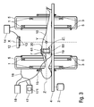
- FIG. 3 Another embodiment of an MR arrangement according to the invention with an excitation coil arrangement 21 is shown in FIG. 3.
- the associated flowchart is shown in FIG. 4 shown.
- the excitation coil arrangement 21 has an excitation coil 19 there, which at the same time can also work as a receiving coil. This forms the reception coil together with further receiving coils 61 and 63 and a fourth, not visible Receiving coil the receiving coil arrangement already shown in FIG. 1. Also the Excitation coil 19 is in turn with the control unit 17 and the reconstruction unit 18 in connection. All other elements of the MR arrangement are similar or in an identical manner to the MR arrangement shown in FIG. 1. Only the excitation coil 11 shown there can be omitted here.
- the sensitivity profile is identical to that for each coil resulting excitation profile when used to generate a magnetic field. It is therefore to achieve a certain stimulation of the examination area required that the excitation field achieved by means of the excitation signal be as precise as possible know. This can be calculated for a coil, for example, if the sensitivity profile the coil is known. It is also clear from this that a change in The position and location of a coil also changes the excitation field of the coil leads, so that the excitation that occurs several times during an MR data acquisition must be adjusted by means of an excitation signal if the position and location the excitation coil changed during the acquisition.
- step 80 First off the initial position and calibration measurements (steps 80 and 81) the initial Excitation profile of the excitation coil determined (for 82). During the acquisition then the position and location of the excitation coil using the same position measuring device are detected (step 83) if the excitation coil also has the position measuring device matched markers 7 are attached. If there is a position and / or A change in the position of the excitation coil results from this measurement be determined in step 84 and then in step 85 the Correct the excitation profile of the excitation coil. This can be done continuously during the Acquisition take place so that the examination area is always with the optimal and desired field of excitation is excited (step 86). To correct the excitation signal For this purpose, suitable correction means 171 are provided in the control unit 17.
- Flexible coil elements which can be deformed to a greater extent, require Position determination more than three points of the coil element to match the deformation to be able to describe.
- the positioning and the corresponding Adjusting the sensitivity profile for a receiving coil is therefore quite complex. It can therefore be advantageous to mechanically limit the flexibility of such coils during the acquisition by taking measures in such coils to to be able to switch between a flexible and a rigid state. Such coils can then be switched to the flexible state to position and thus optimally adapt to the body surface. They are then used for data acquisition however, switched to the stiff state so that deformation is no longer possible and the position determination based on three points on the coils is sufficient to if necessary to be able to determine a movement.
- a such a coil can be produced in an airtight container, for example with small styrofoam balls is filled, is attached to the coil. As long as the container is under normal ambient pressure, the coil is flexible. However, once that If the container is evacuated, the balls are pressed together so that the container is stiff becomes. This technique is known for example from emergency ambulances, where it is used for fixation a patient on the couch is used during transportation.
- such coils could be realized in that a container attached to the coil, which is filled with a material that has a melting point around ambient temperature. If the material is heated by a few degrees, the coil can be made flexible because the material liquefies; becomes the material cooled down again, it solidifies, so that the coil is stiff again.
- This material should be designed so that it delivers an MR signal during a calibration measurement, but delivers little or no signal during actual MR data acquisition.
- very short T 2 or T 2 * materials e.g. B. highly concentrated salt solutions or polymers used in combination with MR sequences of very short echo times, e.g. B. TE ⁇ 0.3 ms for the calibration measurement.
- Such materials are then visible in such MR sequences, while they remain invisible in MR sequences with normal echo times as used for the acquisition of the MR data during the imaging.
- the invention can still be applied to the movement as well during the acquisition of a single MR data record with even higher temporal resolution to correct.
- each set of k-space data is used for its Acquisition no significant spool movement has occurred, separately reconstructed.
- the the resulting drawing files are then combined, with the correspondingly valid ones Sensitivity profiles can be used.
- the sensitivity profiles vary in the coding matrix over time and therefore don't just depend on the position in the local space, but also from the position in the frequency space.
- On more general formalism, such as that associated with non-Cartesian Acquisitions using the SENSE process must be proposed then be used in the reconstruction.
- the sensitivity or excitation profile can be corrected using a simple coordinate transformation, if only one Movement or rotation of a coil has occurred. If a coil is deformed the correction much more difficult. Then, for example, the field profile of the coil can be recalculated, if necessary using knowledge of the Tissue sensitivity or by comparison with the initial one in the calibration measurement found profile. Alternatively, models for one could also be used Transformation can be applied.
- the method according to the invention in particular the determined position and Location information, can also be used to mutual coupling or
Abstract
Description
Die Erfindung betrifft ein MR-Verfahren zur Ermittlung von MR-Bildern eines Untersuchungsbereichs eines Untersuchungsobjekts, wobei mittels einer mindestens eine bewegliche und/oder flexible Empfangsspule aufweisenden Emfpangsspulenanordnung MR-Daten aus dem Untersuchungsbereich erfasst werden und wobei aus den erfassten MR-Daten die MR-Bilder rekonstruiert werden. Weiter betrifft die Erfindung ein MR-Verfahren zur Ermittlung von MR-Bildern eines Untersuchungsbereichs eines Untersuchungsobjekts, wobei mittels einer mindestens eine bewegliche und/oder flexible Erregerspule aufweisenden Erregerspulenanordnung der abzubildende Untersuchungsbereich angeregt wird. Die Erfindung betrifft außerdem auch entsprechende MR-Anordnungen mit einer Empfangsspulenanordnung bzw. einer Erregerspulenanordnung und Mitteln zur Ermittlung von Positions- und Lageinformationen der Spulen. Schließlich betrifft die Erfindung auch ein Computerprogramm zur Umsetzung der MR-Verfahren und/oder zur Steuerung der MR-Anordnungen.The invention relates to an MR method for determining MR images of an examination area of an examination subject, with at least one movable and / or flexible receiving coil having receiving coil arrangement MR data be recorded from the examination area and from the recorded MR data the MR images are reconstructed. The invention further relates to an MR method for Determination of MR images of an examination area of an examination object, wherein by means of at least one movable and / or flexible excitation coil Excitation coil arrangement of the examination area to be imaged is excited. The The invention also relates to corresponding MR arrangements with a receiving coil arrangement or an excitation coil arrangement and means for determining Position and position information of the coils. Finally, the invention also relates to a Computer program for implementing the MR methods and / or for controlling the MR arrangements.
In der Magnetresonanztomographie (MR-Tomographie) werden häufig Empfangsspulenanordnungen mit mehreren Empfangsspulen anstelle einer einzigen Empfangsspule verwendet, um bei vorgegebener MR-Sequenz und Akquisitionszeit ein erhöhtes Signal-zu-Rausch-Verhältnis sowie eine verbesserte räumliche Auflösung zu erhalten. Dafür sind geeignete Rekonstruktionsalgorithmen erforderlich, von denen eine Vielzahl bekannt ist. Ein Verfahren, mit dem sich eine starke Verbesserung erzielen lässt, ist das sogenannten SENSE-Verfahren, das aus "SENSE: Sensitivity Encoding for Fast MRI", Pruessmann, K. et al., Magnetic Resonance in Medicine, 42:952-962 (1999) bekannt ist. Das SENSE-Verfahren erlaubt es vornehmlich, die Messzeit mit einem praktikablen Verfahren zu reduzieren. Weitere bekannte Methoden zielen vornehmlich auf eine Verbesserung des Signal-zu-Rausch-Verhältnisses ab. In magnetic resonance imaging (MR tomography), reception coil arrangements are often used used with multiple receiving coils instead of a single receiving coil, in order to increase the signal-to-noise ratio for a given MR sequence and acquisition time as well as to obtain an improved spatial resolution. Are for suitable reconstruction algorithms are required, a large number of which are known. One method with which a great improvement can be achieved is the so-called SENSE method, which results from "SENSE: Sensitivity Encoding for Fast MRI", Pruessmann, K. et al., Magnetic Resonance in Medicine, 42: 952-962 (1999). The SENSE process primarily allows the measurement time to be increased using a practical method to reduce. Other known methods are primarily aimed at improving the Signal-to-noise ratio.
Bei diesem Verfahren werden entweder Informationen über die Empfindlichkeitsprofile dazu benutzt, um individuelle Beiträge (MR-Daten) jeder Empfangsspule zu einem MR-Gesamtbild entsprechend der räumlichen Anordnung zu gewichten oder um zwischen den Beiträgen von verschiedenen räumlichen Orten zu einzelnen erfassten MR-Daten zu differenzieren. Allerdings sind diese Verfahren nicht sehr robust, wenn das tatsächliche Spulenempfindlichkeitsprofil von dem in der Rekonstruktion benutzten Spulenempfindlichkeitsprofil abweicht, so dass in rekonstruierten MR-Bildern dann Intensitäts-Inhomogenitäten und Rückfaltungsartefakte auftreten. Insbesondere das SENSE-Verfahren ist in dieser Hinsicht sehr empfindlich.This procedure either provides information about the sensitivity profiles used to make individual contributions (MR data) of each receiving coil to an overall MR image to weight according to the spatial arrangement or to between the Differentiate contributions from different spatial locations to individual acquired MR data. However, these methods are not very robust if the actual coil sensitivity profile from the coil sensitivity profile used in the reconstruction deviates so that intensity inhomogeneities in reconstructed MR images and refolding artifacts occur. In particular, the SENSE process is in this Very sensitive.
Wenn zur Erfassung von MR-Daten Empfangsspulen verwendet werden, die während der gesamten Datenerfassung nicht an einem festen Ort bleiben, wird die Annahme von invarianten Empfangsspulenempfindlichkeiten verletzt. Insbesondere Bewegungen als auch Deformierungen tragen zu geänderten räumlichen Spulenempfindlichkeiten bei. Eine Möglichkeit, derartigen Änderungen der Empfangsspulenempfindlichkeiten während der Datenerfassung zu begegnen, wäre, bei vermuteten signifikanten Spulenbewegungen erneut Kalibrierungsdaten zu erfassen, um das aktuelle Spulenempfindlichkeitsprofil neu zu bestimmen. Dies würde jedoch einen zusätzlichen Aufwand an Messzeit und Datenverarbeitung erfordern, was abhängig von der jeweiligen Anwendung entweder nicht wünschenswert oder nicht möglich ist.When receiving coils are used for the acquisition of MR data, which during the entire data collection does not stay in one place, the assumption is invariant Receiving coil sensitivity violated. In particular movements as well Deformations contribute to changes in spatial coil sensitivity. A Possibility of such changes in the reception coil sensitivity during the Countering data acquisition would be if significant coil movements were suspected recapture calibration data to re-create the current coil sensitivity profile to determine. However, this would require additional measurement time and data processing do not require what depending on the application either is desirable or not possible.
Auch bei der Anregung des Untersuchungsbereichs mittels einer Erregerspulenanordnung, welche mindestens eine Erregerspule aufweist, wird implizit angenommen, dass die Profile der einzelnen Spulen invariant über die Zeit sind.Even when the examination area is excited by means of an excitation coil arrangement, which has at least one excitation coil, it is implicitly assumed that the profiles of the individual coils are invariant over time.
Der Erfindung liegt deshalb die Aufgabe zugrunde, ein MR-Verfahren und eine MR-Anordnung anzugeben, bei denen MR-Bilder mit verbesserter Bildqualität erstellt werden können, auch wenn bewegliche und/oder flexible Empfangsspulen und/oder Erregerspulen Verwendung finden und bei denen insbesondere die beschriebenen Nachteile vermieden werden. The invention is therefore based on the object of an MR method and an MR arrangement Specify where MR images are created with improved image quality can, even if movable and / or flexible receiving coils and / or excitation coils Find use and in particular the disadvantages described avoided become.
Diese Aufgabe wird erfindungsgemäß durch ein MR-Verfahren gemäß Anspruch 1 und ein
MR-Verfahren gemäß Anspruch 5 gelöst. Bei der Erfassung von MR-Daten wird dabei
vorgeschlagen, Positions- und Lageinformationen der Empfangsspulen zu ermitteln und
die Eingangsdaten der Rekonstruktion anhand der ermittelten Positions- und
Lageinformationen zum Ausgleich von Positions- und/oder Lageveränderungen der
Empfangsspulen während der Erfassung der MR-Daten vor der Rekonstruktion der MR-Bilder
zu korrigieren. Bei der Anregung des Untersuchungsbereichs wird entsprechend
vorgeschlagen, Positions- und Lageinformationen der mindestens einen Erregerspule zu
ermitteln und das Anregungssignal der mindestens einen Erregerspule anhand der
ermittelten Positions- und Lageinformationen zum Ausgleich von Positions- und/oder
Lageveränderungen der mindestens einen Erregerspule zu korrigieren. Die Erfindung wird
außerdem auch durch einen MR-Anordnung nach Anspruch 6 oder 7 sowie durch ein
Computerprogramm gemäß Anspruch 13 gelöst.This object is achieved by an MR method according to
Der Erfindung liegt die Erkenntnis zugrunde, dass es für eine Reihe von Applikationen vorteilhaft ist, nicht vor, während oder nach der Erfassung von MR-Daten erneute Kalibrationsmessungen vorzunehmen, um das Empfindlichkeits- bzw. Anregungsprofil von Spulen neu zu bestimmen, da es sich möglicherweise aufgrund von Bewegungen während oder zwischen Akquisitionen verändert hat, sondern im Verlauf der Messung Positionsund Lageinformationen der Spulen zu erfassen und diese bei der Rekonstruktion der MR-Bilder unmittelbar zu berücksichtigen. Mit geeigneten Mitteln, insbesondere mittels einer Positionsmesseinrichtung, sollen dabei Bewegungen und/oder Deformationen von Spulen erfasst werden. Eine Kalibrationsmessung zur Bestimmung des Empfindlichkeitsprofils der mindestens einen Empfangsspule bzw. des Anregungsprofils der mindestens einen Erregerspule ist somit nur ein einziges Mal vor der Erfassung der MR-Daten erforderlich.The invention is based on the finding that it is suitable for a number of applications It is advantageous not to calibrate again before, during or after the acquisition of MR data to make the sensitivity or excitation profile of Redetermine coils as it may be due to movement during or changed between acquisitions, but in the course of the measurement position and Record the position information of the coils and this during the reconstruction of the MR images to be considered immediately. Using suitable means, in particular using a Position measuring device, should movements and / or deformations of coils be recorded. A calibration measurement to determine the sensitivity profile of the at least one receiving coil or the excitation profile of the at least one The excitation coil is therefore only required once before the MR data are acquired.
Prinzipiell könnte auch vollständig auf Kalibrationsmessungen verzichtet werden, und theoretische Modelle über die Feldverteilung der Spulen könnten genutzt werden, um aus der Kenntnis der Spulenposition und -lage das jeweilige Empfindlichkeitsprofil zu schätzen. Spätere Abweichungen von diesen Profilen können dann anhand der ermittelten Positions- und Lageinformationen korrigiert werden.In principle, calibration measurements could also be dispensed with entirely, and theoretical models about the field distribution of the coils could be used to get out knowledge of the coil position and position to the respective sensitivity profile estimate. Later deviations from these profiles can then be based on the determined Position and location information are corrected.
Wie in bevorzugten Ausgestaltungen vorgesehen ist, können als die genannten Eingangsdaten der Rekonstruktion anhand der gemessenen Positions- und Lageinformationen der Empfangsspulen sowohl die Empfindlichkeitsprofile der einzelnen Empfangsspulen, aus den erfassten MR-Daten der einzelnen Empfangsspulen ermittelte Einzelbilder oder auch die erfassten MR-Daten selbst erfindungsgemäß korrigiert werden, bevor ein MR-Gesamtbild rekonstruiert wirdAs is provided in preferred configurations, the input data mentioned can the reconstruction based on the measured position and location information of the Reception coils as well as the sensitivity profiles of the individual reception coils single images determined or the acquired MR data of the individual receiving coils the acquired MR data itself are corrected according to the invention before an overall MR image is reconstructed
In analoger Weise kann das aus einer anfangs vorgenommenen Kalibrationsmessung gewonnene Anregungsprofil einer Erregerspule anhand der ermittelten Positions- und Lageinformationen der Erregerspule während der Datenerfassung korrigiert werden. In diesem Fall muss die Neuberechnung des Anregungssignals für die einzelnen Sendespulen unmittelbar erfolgen, d. h. aus der ermittelten Position und Lage wird das Empfindlichkeitsprofil geschätzt, daraus das veränderte Anregungssignal berechnet, und dies unmittelbar ausgeführt.Analogously, this can be done from an initial calibration measurement obtained excitation profile of an excitation coil based on the determined position and Position information of the excitation coil can be corrected during data acquisition. In In this case, the recalculation of the excitation signal for the individual transmitter coils take place immediately, d. H. the sensitivity profile is derived from the determined position and location estimated, the changed excitation signal is calculated, and this immediately executed.
Zur Korrektur können beispielsweise affine oder elastische Transformationen verwendet werden, oder es kann auch eine direkte Berechnung des veränderten Profils oder eine Kombination beider Methoden erfolgen. Durch die Erfindung lassen sich somit MR-Bilder mit deutlich erhöhter Bildqualität auch bei Bewegungen oder Deformationen von Empfangs- bzw. Erregerspulen erreichen, und Artefakte können weitgehend vermieden werden.Affine or elastic transformations can be used for correction, for example , or it can also be a direct calculation of the changed profile or a Both methods are combined. The invention thus enables MR images with significantly increased image quality even with movements or deformations of Reach receiving or excitation coils, and artifacts can be largely avoided become.
Zur Ermittlung der Positions- und Lageinformationen wird bevorzugt eine Positionsmesseinrichtung
verwendet. Diese kann grundsätzlich beliebig ausgestaltet sein, beispielsweise
auf einem optischen, elektromagnetischen oder Mikrospulen-basierten Prinzip beruhen. So
kann beispielsweise an einem Stativ eine Kamera angebracht sein, mittels der die Position
von an den Spulen angsbrachten LEDs im Raum mit hoher Genauigkeit bestimmt werden
kann. Wesentlich ist bei der Positionsmesseinrichtung, dass die Messgenauigkeit der Positionsmessung
möglichst groß ist, vorzugsweise in der Größenordnung eines Bildpixels oder
darunter. Vorteilhaft ist weiterhin, wenn die Messung kontinuierlich erfolgen kann.
Grundsätzlich kann jedoch auch die MR-Anordnung selbst, d.h. die Anregungs- und
Empfangsspulen der MR-Anordnung zur Erfassung von Positions- und Lageinformationen
der Spulen verwendet werden.
In einer weiteren Ausgestaltung der erfindungsgemäßen MR-Anordnungen sind flexible
Spulen vorgesehen, die einen steifen Zustand annehmen können, wenn MR-Daten erfasst
werden sollen. Auch hierfür sind verschiedene Prinzipien, wie sie in den Ansprüchen 10
und 11 angsgeben sind, grundsätzlich denkbar. Wesentlich ist dabei, dass die Spulen,
wobei dies sowohl für Erregerspulen als auch für Empfangsspulen gilt, solange flexibel und
beweglich sein können, solange keine Daten erfasst werden. Wenn jedoch die Akquisition
von Daten beginnt, werden die Spulen in den steifen Zustand gebracht, so dass sie sich
nicht mehr oder nur in geringem Maße bewegen oder verbiegen können. Dadurch kann
eine zusätzliche Verbesserung der letztendlich rekonstruierten MR-Bilder erreicht werden.
Der Schmelzpunkt der in der Ausgestaltung gemäß Anspruch 11 verwendeten Flüssigkeit
kann so gewählt sein, dass sie bei Umgebungstemperatur flüssig ist und sich bei wenigen
Grad unterhalb der Umgebungstemperatur verfestigt, so dass die Spulen durch Kühlen des
Behältnisses bei der Datenerfassung in den steifen Zustand gebracht werden können oder
dass sie bei Umgsbungstemperatur fest ist und sich bei wenigen Grad oberhalb der Umgebungstemperatur
verflüssigt, so dass die Spulen durch Erwärmen des Behältnisses bei der
Positionierung der Spulen in den flexiblen Zustand gebracht werden können.A position measuring device is preferably used to determine the position and position information. In principle, this can be of any design, for example based on an optical, electromagnetic or micro-coil-based principle. For example, a camera can be attached to a tripod, by means of which the position of LEDs attached to the coils in the room can be determined with high accuracy. It is essential in the position measuring device that the measurement accuracy of the position measurement is as large as possible, preferably in the order of magnitude of an image pixel or less. It is also advantageous if the measurement can be carried out continuously. In principle, however, the MR arrangement itself, ie the excitation and reception coils of the MR arrangement, can also be used to acquire position and position information of the coils.
In a further embodiment of the MR arrangements according to the invention, flexible coils are provided which can assume a rigid state if MR data are to be acquired. Various principles as set out in
In einer weiteren Ausgsstaltung der erfindungsgemäßen MR-Anordnungen ist vorgssehen, in Lücken zwischen dem Untersuchungsobjekt und einer oder mehreren Spulen der Empfangsspulen- bzw. Erregerspulenanordnung ein Material anzuordnen, welches bei der Erfassung der MR-Daten kein MR-Signal liefert, sondern nur während einer Kalibrationsmessung zur Bestimmung der Spulenempfindlichkeit einer Empfangsspule bzw. zur Bestimmung des Erregerfeldes einer Anregungsspule ein MR-Signal liefert. Dadurch kann erreicht werden, dass das mittels der Kalibrationsmessung erfasste Empfindlichkeitsprofil bzw. Erregerfeld mit hoher Genauigkeit bestimmt werden kann, da es in dem Zwischenraum zwischen dem Untersuchungsobjekt und der Spule keinen Signalverlust gibt während der Kalibrationsmessung. Somit ist auch in diesem Zwischenraum nach der Kalibrationsmessung das Empfindlichkeitsprofil bzw. das Erregerfeld bekannt. Andererseits liefert das in diesem Zwischenraum befindliche Material keinen Beitrag zu den gemessenen MR-Daten, so dass das MR-Bild letztlich dadurch nicht verfälscht wird. Die Bestimmung des Empfindlichkeitsprofils im Außenraum' des Patienten ist insbesondere deshalb von Interesse ist, da eine folgende Bewegung dazu führen kann, dass Schätzungen für diesen Bereich plötzlich benötigt werden in der Bildrekonstruktion.In a further embodiment of the MR arrangements according to the invention, in gaps between the object to be examined and one or more coils of the Reception coil or excitation coil arrangement to arrange a material which in the Acquisition of the MR data does not provide an MR signal, but only during a calibration measurement for determining the coil sensitivity of a receiving coil or for Determination of the excitation field of an excitation coil delivers an MR signal. This can achieved that the sensitivity profile detected by means of the calibration measurement or excitation field can be determined with high accuracy because it is in the space there is no signal loss between the test object and the coil during the calibration measurement. Thus, in this space after Calibration measurement known the sensitivity profile or the excitation field. on the other hand the material in this gap does not contribute to the measured MR data, so that the MR image is ultimately not falsified by this. The determination the sensitivity profile in the patient's outside space is therefore particularly of Interest is because a subsequent move can cause estimates for this Area suddenly needed in the image reconstruction.
Die Erfindung wird nachfolgend anhand der Zeichnungen näher erläutert. Es zeigen:
Figur 1- eine erfindungsgemäße MR-Anordnung mit einer Empfangsspulenanordnung,
Figur 2- ein Ablaufdiagramm eines erfindungsgämäßen MR-Verfahrens zur Anwendung
bei einer MR-Anordnung nach
Figur 1, Figur 3- eine erfindungsgemäße MR-Anordnung mit einer Erregerspulenanordnung und
Figur 4- ein Ablaufdiagram eines erfindungsgemäßen MR-Verfahrens zur Anwendung
bei einer MR-Anordnung gemäß
Figur 3.
- Figure 1
- an MR arrangement according to the invention with a receiving coil arrangement,
- Figure 2
- 2 shows a flowchart of an MR method according to the invention for use in an MR arrangement according to FIG. 1,
- Figure 3
- an MR arrangement according to the invention with an excitation coil arrangement and
- Figure 4
- 3 shows a flowchart of an MR method according to the invention for use in an MR arrangement according to FIG. 3.
In Figur 1 ist eine erste Ausgestaltung einer erfindungsgemäßen MR-Anordnung mit einer
Empfangsspulenanordnung gezeigt. Diese MR-Anordnung weist einen
Hauptfeldmagneten 1 auf, der in z-Richtung ein stationäres und im wesentlichen
homogenes Magnetfeld mit einer Stärke von z. B. 1,5 Tesla erzeugt. Der Hauptfeldmagnet
1 ist konzentrisch um die z-Achse und den auf einem Patiententisch 4 liegend
angeordneten Patienten 10 angeordnet. Da der Hauptfeldmagnet 1 zweigeteilt ausgestaltet
ist, ist der mittlere Bereich des Körpers des Patienten 10 von außen zugänglich.FIG. 1 shows a first embodiment of an MR arrangement according to the invention with a
Receiving coil arrangement shown. This MR arrangement has one
Weiterhin sind verschiedene Gradientenspulen-Anordnungen 3, 5 vorgesehen, mit denen
in z-Richtung verlaufende Gradienten-Magnetfelder mit einem Gradienten in x-, y- bzw.
z-Richtung erzeugt werden können. Zur Anregung des Untersuchungsbereichs ist eine
Erregerspulenanordnung vorgesehen, die vorliegend nur eine einzige stationäre Erregerspule
11 umfasst. Diese Spule 11 kann gleichzeitig auch als stationäre Empfangsspule
eingesetzt werden. Mittels eines Motors 2 kann der auf dem Patiententisch 4 liegende
Patient 10 in z-Richtung verfahren werden, um den Untersuchungsbereich innerhalb des
stationären Magnetfeldes am besten zu positionieren. Weitere bei einer MR-Anordnung
notwendigerweise vorhandene Elemente wie beispielsweise Verstärker für die einzelnen
Spulen, Generatoren, Bedien- und Anzeigeelemente sind allgemein bekannt und sollen
deshalb nicht näher gezeigt und erläutert werden.Furthermore, various
Mittels einer Empfangsspulenanordnung 6, die rings um den Patienten 10 um den Untersuchungsbereich,
vorliegend den Brustkorb in Höhe des Herzens, angeordnet ist, sollen die
im Untersuchungsbereich erzeugten MR-Signale erfasst werden. Die erfassten MR-Daten
werden über eine Verbindungsleitung 15 einer Steuereinheit 17 und einer Rekonstruktionseinheit
18 zugeführt. Beide Einheiten 17,18 stehen auch über eine Leitung 16 mit
allen weiteren Spulen 1, 3, 5, 11 in Verbindung. Mittels der Steuereinheit 17 wird die
MR-Anordnung gesteuert, insbesondere die Erzeugung der zur Datenerfassung erforderlichen
Magnetfelder. Mittels der Rekonstruktionseinheit 18 werden die insbesondere von
der Empfangsspulenanordnung 6 erfassten MR-Daten verarbeitet und gewünschte MR-Bilder
daraus erzeugt.By means of a receiving
Im vorliegenden Fall weist die Empfangsspulenanordnung 6 vier Empfangsspulen 61, 62,
63 (eine vierte Empfangsspule befindet sich gegenüberliegend der Empfangsspule 62 und
ist deshalb nicht sichtbar) auf, die rings um den Brustkorb des Patienten 10 herum
angeordnet sind. Diese Empfangsspulen 61, 62, 63 sind flexibel ausgestaltet, um sich der
Körperoberfläche des Patienten 10 möglichst gut anpassen zu können. Außerdem sind die
Empfangsspulen 61, 62, 63 grundsätzlich zwar durch mit Klettverschlüssen versehene
dehnbare Bänder provisorisch fixiert, aber dennoch beweglich, das heißt, sie können bei
Bewegungen des Patienten 10 während der Datenerfassung ihre Position und Lage ändern,
beispielsweise verrutschen, verdreht oder gar verbogen werden.In the present case, the receiving
Zur Erfassung der jeweils aktuellen Position der Empfangsspulen 61, 62, 63 während der
Datenerfassung ist deshalb erfindungsgämäß eine Positionsmesseinrichtung vorgesehen.
Diese weist im vorliegenden Fall eine Kameraeinheit 12 mit zwei voneinander beabstandeten
Kameras 13, beispielsweise CCD-Kameras, auf, die über eine Recheneinheit 14 mit
dem gesamten System und somit auch mit der Steuereinheit 17 und der Rekonstruktionseinheit
18 verbunden sind. Die Kameras 13 sind so ausgestaltet und ausgerichtet, dass sie
optische Signale, die von speziell dafür vorgesehenen optischen Markern 7, beispielsweise
im sichtbaren oder Infrarot-Bereich arbeitenden LEDs, empfangen können, die an jeder
der Empfangsspulen 61, 62, 63 angeordnet sind. Die Anzahl und Anordnung der optischen
Marker 7 ist dabei derart vorgesehen, dass sich aus den einzelnen Positionen der
Marker 7 die Position und Lage der zugehörigen Empfangsspule bestimmen lässt. Insbesondere
sollen Positions- und Lageveränderungen der Empfangsspulen 61, 62, 63 während
der Datenerfassung mittels der Kameras 13 detektiert werden. Zur Auswertung der gemessenen
Positionsdaten werden diese an eine entsprechende Recheneinheit 14 geliefert, die
zunächst die räumlich Position der einzelnen optischen Marker 7 bestimmt, daraus die
Position und Lage der einzelnen Empfangsspulen 61, 62, 63 ermittelt und anhand dessen
feststellt, ob sich Positions- und/oder Lageveränderungen ergeben haben verglichen mit
einer Referenzmessung.To detect the current position of the receiving coils 61, 62, 63 during the
According to the invention, a position measuring device is therefore provided for data acquisition.
In the present case, this has a
Zwar kann die Positionsbestimmung einzelner Spulen, wie z. B. der Spule 63, Schwierigkeiten
bereiten. Einerseits wird jedoch davon ausgegangen, dass diese Spule sich nur wenig
bis gar nicht bewegen kann. Andererseits können auch andere Verfahren, z.B. elektromagnetische
Verfahren, verwendet werden, um die Position solcher Spulen zu bestimmen.The position determination of individual coils, such as. B. the
Sofern Positions- und/oder Lageveränderungen festgestellt werden, kann mittels einer
Korrektureinheit 181 in der Rekonstruktionseinheit 18 eine Korrektur der Eingangsdaten
der Rekonstruktion vorgenommen werden. Dazu kann beispielsweise für jede Empfangsspule
61, 62, 63 einzeln das jeweilige räumliche Empfindlichkeitsprofil, das aus einer eingangs
vorgenommenen Kalibrationsmessung bekannt ist, korrigiert, insbesondere räumlich
angepasst, werden. Alternativ können auch aus den ermittelten MR-Daten jeweils einer
Empfangsspule 61, 62, 63 erstellte MR-Einzelbilder zunächst korrigiert werden, bevor sie
zu einem MR-Gesamtbild kombiniert werden. Als weitere Alternative könnten auch die
MR-Daten direkt korrigiert werden, bevor die Einzelbilder und daraus dann das MR-Gesamtbild
rekonstruiert werden. If changes in position and / or location are determined, a
Anhand des Ablaufdiagramms in Figur 2 soll nun das erfindungsgemäße MR-Verfahren
noch näher erläutert werden. In einem ersten Schritt 70 wird für die anfängliche Spulenkonfiguration
die Position und Orientierung jeder einzelnen Empfangsspule 61, 62, 63
bestimmt. In einem Kalibrationsschritt 71 wird außerdem eine Kalibrationsmessung
durchgeführt. Dabei sollte sichergestellt werden, dass sich Position und Orientierung der
Empfangsspulen nicht verändern. Dies ist zum Beispiel durch geeignete Messverfahren mit
Gating oder Triggering möglich, die es nicht erforderlich machen, die Spulen in irgend
einer Weise zu fixieren für die Dauer dieser Messung. Im allgemeinen beträgt die Messzeit
für die Kalibrationsmessung allerdings nur etwa eine Minute. Daher ist dabei das Problem
der Patientenbewegung relativ klein.The MR method according to the invention is now to be described with reference to the flow chart in FIG
to be explained in more detail. In a
In einem nachfolgenden Schritt 72 kann dann aus den ermittelten Daten der Schritte 70
und 71 das räumliche Empfindlichkeitsprofil der einzelnen Empfangsspulen ermittelt
werden.In a
Während der Akquisition der MR-Daten kann nun laufend oder in regelmäßigen Zeitabständen
mittels der Positionsmesseinrichtung die Position und Lage der einzelnen
Empfangsspulen überwacht werden (Schritt 73). Falls eine, ein bestimmtes Maß überschreitende
Veränderung der Position oder Lage, beispielsweise ein Verschieben einer
Empfangsspule oder eine Deformation einer Empfangsspule, festgestellt wird, kann dann
in Schritt 74 eine entsprechende Transformation des eingangs bestimmten Empfindlichkeitsprofils
der betroffenen Empfangsspule bestimmt werden, um dieses dann im Schritt
75 entsprechend zu korrigieren. Das entsprechend korrigierte Empfindlichkeitsprofil wird
dann auch bei der Rekonstruktion in Schritt 77 verwendet, bei der die aus den von den
einzelnen Empfangsspulen erfassten MR-Daten ermittelten Einzelbilder (Schritt 76)
kombiniert werden, um ein darstellbares und gewünschtes MR-Gesamtbild zu erzeugen
(Schritt 78).During the acquisition of the MR data can now be ongoing or at regular intervals
the position and location of the individual by means of the position measuring device
Receiving coils are monitored (step 73). If one exceeds a certain dimension
Change in position or location, for example moving one
Receiving coil or a deformation of a receiving coil, can then be determined
in step 74 a corresponding transformation of the sensitivity profile determined at the beginning
the receiving coil concerned can be determined to this then in
Es wurde bereits erwähnt, dass die Positions- und Lagebestimmung in Schritt 73 laufend
während der Akquisition der MR-Daten erfolgen kann. Deshalb kann grundsätzlich für
jeden MR-Datensatz das jeweils aktuelle Empfindlichkeitsprofil der einzelnen Empfangsspulen
bestimmt werden, wodurch sich die höchste Genauigkeit erreichen lässt. In diesem
Fall wird im Prinzip für jeden Messwert ein eigenständiger Satz von Empfindlichkeitsprofilen
der Rekonstruktion zur Verfügung gestellt. Die Rekonstruktionsverfahren müssen
entsprechend modifiziert werden, um die zeitliche Abhängigkeit der einzelnen Messdaten
von den unterschiedlichen Empfindlichkeitsprofilen zu berücksichtigen.It has already been mentioned that the position and attitude determination in
Tritt beispielsweise nach der Hälfte der Datenakquisition für ein Bild eine signifikante Bewegung der Spulen auf, so kann bevorzugt die Rekonstruktion separat für beide Teildatensätze ausgeführt werden mit einem entsprechend verdoppelten Reduktionsfaktor. Im Anschluss sind die jeweiligen Ergsbnisse geeignet zu kombinieren.For example, a significant image occurs halfway through data acquisition Movement of the coils, the reconstruction can preferably be carried out separately for both partial data sets be carried out with a correspondingly doubled reduction factor. in the Connection, the respective results are to be combined appropriately.
Für das beschriebene Verfahren ist allerdings ein hoher Rechenaufwand erforderlich. Vorzugsweise wird nur dann ein korrigiertes Empfindlichkeitsprofil für einzelne Empfangsspulen bestimmt, wenn die Bewegung oder Deformation einer Empfangsspule ein bestimmtes Maß überschritten hat. Jedoch lässt sich auch damit eine deutliche Verbesserung in der Bildqualität sowie eine höhere räumliche und zeitliche Auflösung von MR-Bildem erreichen.However, a high computing effort is required for the described method. Preferably is only then a corrected sensitivity profile for individual receiving coils determines when the movement or deformation of a receiving coil occurs has exceeded certain dimensions. However, this can also be a significant improvement in the image quality as well as a higher spatial and temporal resolution of MR images to reach.
Eine weitere Ausgsstaltung einer erfindungsgemäßen MR-Anordnung mit einer Erregerspulenanordnung
21 ist in Figur 3 gezeigt. Das zugehörige Ablaufdiagramm ist in Figur 4
gezeigt. Die Erregerspulenanordnung 21 weist dort eine Erregerspule 19 auf, die gleichzeitig
auch als Empfangsspule arbeiten kann. Als Empfangsspule bildet diese somit zusammen
mit weiteren Empfangsspulen 61 und 63 sowie einer vierten, nicht sichtbaren
Empfangsspule die auch bereits in Figur 1 gezeigte Empfangsspulenanordnung. Auch die
Anregungsspule 19 steht wiederum mit der Steuereinheit 17 und der Rekonstruktionseinheit
18 in Verbindung. Alle weiteren Elemente der MR-Anordnung sind in ähnlicher
oder identischer Weise wie bei der in Figur 1 gezeigten MR-Anordnung vorhanden. Lediglich
die dort gezeigte Erregerspule 11 kann hier entfallen.Another embodiment of an MR arrangement according to the invention with an
Aufgrund der Reziprozität ist für jede Spule das Empfindlichkeitsprofil identisch zu dem resultierenden Anregungsprofil, wenn sie zur Erzeugung eines Magnetfeldes benutzt wird. Um eine bestimmte Anregung des Untersuchungsbereichs zu erreichen, ist es deshalb erforderlich, das mittels des Anregungssignal erzielte Anregungsfeld möglichst genau zu kennen. Dieses kann beispielsweise für eine Spule berechnet werden, wenn das Empfindlichkeitsprofil der Spule bekannt ist. Daraus wird auch klar, dass eine Veränderung der Position und Lage einer Spule auch zu einer Veränderung des Anregungsfeldes der Spule führt, so dass die während einer MR-Daten-Akquisition mehrfach erfolgende Anregung mittels eines Anregungssignals angepasst werden muss, wenn sich die Position und Lage der Anregungsspule während der Akquisition verändert.Due to the reciprocity, the sensitivity profile is identical to that for each coil resulting excitation profile when used to generate a magnetic field. It is therefore to achieve a certain stimulation of the examination area required that the excitation field achieved by means of the excitation signal be as precise as possible know. This can be calculated for a coil, for example, if the sensitivity profile the coil is known. It is also clear from this that a change in The position and location of a coil also changes the excitation field of the coil leads, so that the excitation that occurs several times during an MR data acquisition must be adjusted by means of an excitation signal if the position and location the excitation coil changed during the acquisition.
Dies ist in dem in Figur 4 gezeigten Ablaufdiagramm näher erläutert. Zunächst wird aus
den anfänglichen Positions- und Kalibrationsmessungen (Schritte 80 und 81) das anfängliche
Anregungsprofil der Erregerspule bestimmt (für 82). Während der Akquisition kann
dann auch die Position und Lage der Erregerspule mittels derselben Positionsmesseinrichtung
detektiert werden (Schritt 83), wenn an der Erregerspule ebenfalls die auf die Positionsmesseinrichtung
abgestimmten Marker 7 angebracht sind. Wenn sich eine Positionsund/oder
Lageveränderung der Erregerspule aus dieser Messung ergibt, kann eine Transformationsvorschrift
in Schritt 84 bestimmt werden, um anschließend in Schritt 85 das
Anregungsprofil der Erregerspule zu korrigieren. Dies kann somit laufend während der
Akquisition erfolgen, so dass der Untersuchungsbereich immer mit dem optimalen und
gewünschten Erregerfeld angeregt wird (Schritt 86). Zur Korrektur des Anregungssignals
sind dazu in der Steuereinheit 17 geeignete Korrekturmittel 171 vorgesehen.This is explained in more detail in the flow chart shown in FIG. 4. First off
the initial position and calibration measurements (
Dieses Verfahren führt letztlich wiederum dazu, dass aufgrund der größeren Übereinstimmung zwischen gewünschter Anregung und tatsächlicher Anregung MR-Bilder mit höherer Genauigkeit und insbesondere größerer zeitlicher und räumlicher Auflösung erstellt werden können.This procedure ultimately leads to that due to the greater agreement between desired excitation and actual excitation MR images with higher Accuracy and in particular greater temporal and spatial resolution created can be.
Als Positionsmesseinrichtung kommt grundsätzlich jede Messeinrichtung in Frage, bei der
mit möglichst geringem Aufwand die Position und Lage der Spulen möglichst genau bestimmt
werden kann. Beispielhaft sollen hier einige Möglichkeiten näher erläutert werden:
Flexible Spulenelemente, die in stärkerem Maße deformiert werden können, erfordern zur Positionsbestimmung mehr als drei Punkte des Spulenelements, um die Deformation entsprechend beschreiben zu können. Die Positionsbestimmung und die entsprechende Anpassung des Empfindlichkeitsprofils bei einer Empfangsspule ist deshalb recht komplex. Es kann deshalb vorteilhaft sein, die Flexibilität solcher Spulen mechanisch zu begrenzen während der Akquisition, indem bei solchen Spulen Maßnahmen vorgesehen werden, um zwischen einem flexiblen und einem steifen Zustand umschalten zu können. Solche Spulen können dann in den flexiblen Zustand geschalten werden, um sie zu positionieren und somit optimal an die Körperoberfläche anzupassen. Zur Datenerfassung werden sie dann jedoch in den steifen Zustand geschaltet, so dass keine Deformierung mehr möglich ist und die Positionsbestimmung anhand von drei Punkten auf den Spulen ausreicht, um gegebenenfalls eine Bewegung feststellen zu können.Flexible coil elements, which can be deformed to a greater extent, require Position determination more than three points of the coil element to match the deformation to be able to describe. The positioning and the corresponding Adjusting the sensitivity profile for a receiving coil is therefore quite complex. It can therefore be advantageous to mechanically limit the flexibility of such coils during the acquisition by taking measures in such coils to to be able to switch between a flexible and a rigid state. Such coils can then be switched to the flexible state to position and thus optimally adapt to the body surface. They are then used for data acquisition however, switched to the stiff state so that deformation is no longer possible and the position determination based on three points on the coils is sufficient to if necessary to be able to determine a movement.
Für solche Spulen sind verschiedene Ausgestaltungen denkbar. Beispielsweise kann eine solche Spule hergestellt werden, in dem ein luftdichtes Behältnis, das beispielsweise mit kleinen Styroporkugeln gefüllt ist, an der Spule angebracht wird. So lange, wie das Behältnis unter normalen Umgebungsdruck steht, ist die Spule flexibel. Sobald jedoch das Behältnis evakuiert wird, werden die Kugeln aneinandergepresst, so dass das Behältnis steif wird. Diese Technik ist beispielsweise aus Notarztwagen bekannt, wo sie zur Fixierung eines Patienten auf der Krankenliege während des Transports benutzt wird.Various configurations are conceivable for such coils. For example, a such a coil can be produced in an airtight container, for example with small styrofoam balls is filled, is attached to the coil. As long as the container is under normal ambient pressure, the coil is flexible. However, once that If the container is evacuated, the balls are pressed together so that the container is stiff becomes. This technique is known for example from emergency ambulances, where it is used for fixation a patient on the couch is used during transportation.
Als zweite Möglichkeit könnten solche Spulen dadurch realisiert werden, dass ein Behältnis an der Spule angebracht ist, das mit einem Material gefüllt ist, das einen Schmelzpunkt etwa bei Umgebungstemperatur aufweist. Wird das Material um wenige Grad erhitzt, kann die Spule flexibel gemacht werden, da sich das Material verflüssigt; wird das Material wieder abgekühlt, verfestigt es sich, so dass die Spule wieder steif ist.As a second possibility, such coils could be realized in that a container attached to the coil, which is filled with a material that has a melting point around ambient temperature. If the material is heated by a few degrees, the coil can be made flexible because the material liquefies; becomes the material cooled down again, it solidifies, so that the coil is stiff again.
Es sind Fälle denkbar, bei denen eine anfänglich Bestimmung des Anregungs- bzw.
Empfindlichkeitsprofils einer Spule nicht für alle Ortspunkte möglicht ist, da
beispielsweise in bestimmten Regionen innerhalb oder außerhalb des Patienten kein MR-Signal
während der Kalibrationsmessung gemessen werden kann. Die Transformation des
Anregungs- bzw. Empfindlichkeitsprofils zur Berücksichtigung von Positions- und
Lageveränderungen erfordert deshalb oft Extrapolationen. Derartige Extrapolationen
können auf Basis verschiedener Prinzipien durchgeführt werden, beispielsweise mittels
lokaler oder globaler Anpassungen an analytische Funktionen wie Polynome oder an
theoretisch bekannte Empfindlichkeitsprofilverteilungen von Spulen. Alternativ dazu
besteht jedoch auch die Möglichkeit, eine eventuelle Lücke zwischen einer Spule und dem
Patienten mit einem Material 20 auszufüllen, wie es in Figur 3 gezeigt ist. Dieses Material
sollte so ausgestaltet sein, dass es während einer Kalibrationsmessung ein MR-Signal liefert,
aber während der tatsächlichen MR-Datenerfassung nur ein geringes oder kein Signal
liefert. Dazu werden vorzugsweise sehr kurze T2- oder T2*-Materialien, z. B. hochkonzentrierte
Salzlösungen oder Polymere verwendet in Kombination mit MR-Sequenen
von sehr kurzen Echozeiten, z. B. TE<0.3 ms für die Kalibrationsmessung. In solchen MR-Sequenzen
sind derartige Materialien dann sichtbar, während sie in MR-Sequenzen mit
normalen Echozeiten wie für die Erfassung der MR-Daten während der Bildgebung
verwendet unsichtbar bleiben.Cases are conceivable in which an initial determination of the excitation or sensitivity profile of a coil is not possible for all location points, since for example in certain regions inside or outside the patient no MR signal can be measured during the calibration measurement. The transformation of the excitation or sensitivity profile to take into account changes in position and location therefore often requires extrapolations. Such extrapolations can be carried out on the basis of various principles, for example by means of local or global adaptations to analytical functions such as polynomials or to theoretically known sensitivity profile distributions of coils. Alternatively, however, there is also the possibility of filling a possible gap between a coil and the patient with a
Die Erfindung kann noch weitergehend auch angswendet werden, um die Bewegung auch während der Akquisition eines einzigen MR-Datensatzes mit noch höherer zeitlicher Auflösung zu korrigieren. Im einfachsten Fall wird jeder Satz von k-Raum-Daten, bei dessen Akquisition keine signifikante Spulenbewegung aufgstreten ist, separat rekonstruiert. Die resultierenden Teilbilder werden dann kombiniert, wobei die entsprechend gültigen Empfindlichkeitsprofile benutzt werden. In schwierigeren Fällen variieren die Empfindlichkeitsprofile in der Kodierungsmatrix mit der Zeit und hängen deshalb nicht nur von der Position im Ortsraum, sondern auch von der Position im Frequenzraum ab. Ein allgemeinerer Formalismus, wie er beispielsweise im Zusammenhang mit nicht-karthesischen Akquisitionen unter Benutzung des SENSE-Verfahrens vorgeschlagen wird, muss dann bei der Rekonstruktion angewendet werden.The invention can still be applied to the movement as well during the acquisition of a single MR data record with even higher temporal resolution to correct. In the simplest case, each set of k-space data is used for its Acquisition no significant spool movement has occurred, separately reconstructed. The the resulting drawing files are then combined, with the correspondingly valid ones Sensitivity profiles can be used. In more difficult cases, the sensitivity profiles vary in the coding matrix over time and therefore don't just depend on the position in the local space, but also from the position in the frequency space. On more general formalism, such as that associated with non-Cartesian Acquisitions using the SENSE process must be proposed then be used in the reconstruction.
Grundsätzlich kann eine Korrektur des Empfindlichkeits- bzw. Anregungsprofils mittels einer einfachen Koordinatentransformation vorgenommen werden, wenn lediglich eine Bewegung oder Verdrehung einer Spule erfolgt ist. Bei einer Deformation einer Spule ist die Korrektur wesentlich schwieriger. Dann könnte beispielsweise das Feldprofil der Spule neu berechnet werden, gegebenenfalls unter Ausnutzung von Kenntnissen über die Gewebeempfindlichkeit oder durch einen Vergleich mit dem anfänglichen bei der Kalibrationsmessung gefundenen Profil. Alternativ könnten dann auch Modelle für eine Transformation angewendet werden.In principle, the sensitivity or excitation profile can be corrected using a simple coordinate transformation, if only one Movement or rotation of a coil has occurred. If a coil is deformed the correction much more difficult. Then, for example, the field profile of the coil can be recalculated, if necessary using knowledge of the Tissue sensitivity or by comparison with the initial one in the calibration measurement found profile. Alternatively, models for one could also be used Transformation can be applied.
Schließlich kann das erfindungsgämaße Verfahren, insbesondere die ermittelten Positionsund Lageinformation, auch dazu verwendet werden, die gegenseitige Kopplung bzw. Finally, the method according to the invention, in particular the determined position and Location information, can also be used to mutual coupling or
Rauschkorrelation zweier benachbarter Spulen zu bestimmen. Diese Kenntnis kann dann dazu genutzt werden, um eine verbesserte virtuelle Entkopplung der Spulen vorzunehmen, um so letztendlich wieder MR-Bilder mit verbesserter Bildqualität zu erhalten.To determine noise correlation between two adjacent coils. This knowledge can then can be used to improve the virtual decoupling of the coils, to ultimately get MR images with improved image quality.
Claims (13)
dadurch gekennzeichnet, dass bei der Erfassung der MR-Daten Positions- und Lageinformationen der mindestens einen Empfangsspule (61, 62, 63) ermittelt werden und dass Eingangsdaten der Rekonstruktion anhand der ermittelten Positions- und Lageinformtionen zum Ausgleich von Positions- und/oder Lageveränderungen der mindestens einen Empfangsspule (61, 62, 63) während der Erfassung der MR-Daten vor der Rekonstruktion der MR-Bilder korrigiert werden.MR method for determining MR images of an examination area of an examination subject (10), wherein MR data from the examination area are acquired by means of an receiving coil arrangement (6) having at least one movable and / or flexible reception coil (61, 62, 63) and wherein the MR images are reconstructed from the acquired MR data,
characterized in that position and position information of the at least one receiving coil (61, 62, 63) is determined during the acquisition of the MR data and that input data of the reconstruction on the basis of the determined position and position information to compensate for position and / or position changes of the at least one receiving coil (61, 62, 63) is corrected during the acquisition of the MR data before the reconstruction of the MR images.
dadurch gekennzeichnet, dass anhand der Positions- und Lageinformationen das Empfindlichkeitsprofil der mindestens einen Empfangsspulen (61, 62, 63) korrigiert wird.MR method according to claim 1,
characterized in that the sensitivity profile of the at least one receiving coils (61, 62, 63) is corrected on the basis of the position and position information.
dadurch gekennzeichnet, dass anhand der Positions- und Lageinformationen aus den erfassten MR-Daten der mindestens einen Empfangsspule (61, 62, 63) ermittelte Einzelbilder korrigiert werden vor einer Kombination der Einzelbilder zu einem MR-Gesamtbild. MR method according to claim 1,
characterized in that individual images determined from the acquired MR data of the at least one receiving coil (61, 62, 63) are corrected on the basis of the position and position information before a combination of the individual images to form an overall MR image.
dadurch gekennzeichnet, dass anhand der Positions- und Lagsinformationen die erfassten MR-Daten der mindestens einen Empfangsspule (61, 62, 63) korrigiert werden.MR method according to claim 1,
characterized in that the acquired MR data of the at least one receiving coil (61, 62, 63) are corrected on the basis of the position and position information.
dadurch gekennzeichnet, dass bei der Anregung des Untersuchungsbereichs Positions- und Lageinformationen der mindestens eine Erregerspule (19) ermittelt werden und dass das Anregungssignal der mindestens einen Erregerspule (19) anhand der ermittelten Positions- und Lageinformationen zum Ausgleich von Positions- und/oder Lageveränderungen der mindestens einen Erregerspule (19) während der Anregung korrigiert wird.MR method for determining MR images of an examination area of an examination object (10), the examination area to be imaged being excited by means of an excitation coil arrangement (21) having at least one movable and / or flexible excitation coil (19),
characterized in that when the examination area is excited, position and position information of the at least one excitation coil (19) is determined and that the excitation signal of the at least one excitation coil (19) is based on the determined position and position information to compensate for changes in position and / or position of the at least one excitation coil (19) is corrected during the excitation.
dadurch gekennzeichnet, dass die Rekonstruktionseinheit (18) Mittel (181) aufweist zur Korrektur von Eingangsdaten der Rekonstruktion anhand der ermittelten Positions- und Lageinformationen der mindestens einen Empfangsspule (61, 62, 63) vor der Rekonstruktion der MR-Bilder zum Ausgleich von Positions- und/oder Lageveränderungen der mindestens einen Empfangsspule (61, 62, 63) während der Erfassung der MR-Daten. MR arrangement for determining MR images of an examination area of an examination object with a reception coil arrangement (6) having at least one movable and / or flexible reception coil (61, 62, 63) for recording MR data from the examination area, with a reconstruction unit (18 ) for the reconstruction of MR images from the acquired MR data and with means (12, 13) for acquiring position and position information of the at least one receiving coil (61, 62, 63),
characterized in that the reconstruction unit (18) has means (181) for correcting input data of the reconstruction based on the determined position and position information of the at least one receiving coil (61, 62, 63) before the reconstruction of the MR images to compensate for position and / or changes in position of the at least one receiving coil (61, 62, 63) during the acquisition of the MR data.
dadurch gekennzeichnet, dass die Steuereinheit (17) Mittel (171) aufweist zur Korrektur des Anregungssignals der mindestens einen Erregerspule (19) zum Ausgleich von Positions- und/oder Lageveränderungen der mindestens einen Erregerspule (19) während der AnregungMR arrangement for determining MR images of an examination area of an examination object (10) with an excitation coil arrangement (21) having at least one excitation coil (19) for excitation of the examination area to be imaged, with a control unit (17) for controlling the excitation coil arrangement (21) and with Means (12, 13) for determining position and position information of the at least one excitation coil (19) when the examination area is excited,
characterized in that the control unit (17) has means (171) for correcting the excitation signal of the at least one excitation coil (19) to compensate for changes in position and / or position of the at least one excitation coil (19) during the excitation
dadurch gekennzeichnet, dass eine Positionsmesseinrichtung (12, 13), insbesondere eine optische, elektromagnetische oder Mikrospulen-basierte Positionsmesseinrichtung zur Ermittlung der Positionsund Lageinformationen vorgesehen ist.MR arrangement according to claim 6 or 7,
characterized in that a position measuring device (12, 13), in particular an optical, electromagnetic or micro-coil-based position measuring device is provided for determining the position and position information.
dadurch gekennzeichnet, dass die Empfangsspulenanordnung (6) bzw. die Erregerspulenanordnung (21) flexible Spulen aufweist, die einen steifen Zustand annehmen können und dass die Spulen zur Erfassung der MR-Daten in den steifen Zustand gebracht werden.MR arrangement according to claim 6 or 7,
characterized in that the receiving coil arrangement (6) or the excitation coil arrangement (21) has flexible coils which can assume a rigid state and that the coils are brought into the rigid state for recording the MR data.
dadurch gekennzeichnet, dass die Spulen der Empfangsspulenanordnung (6) und/oder der Erregerspulenanordnung (21) je ein luftdichtes Behältnis aufweisen, in dem ein Füllmaterial derart angeordnet ist, dass die Spulen in normalem Zustand flexibel und während der Erfassung der MR-Daten durch zumindest teilweise Evakuierung des Behältnisses steif sind. MR arrangement according to claim 9,
characterized in that the coils of the receiving coil arrangement (6) and / or the excitation coil arrangement (21) each have an airtight container in which a filling material is arranged such that the coils are flexible in the normal state and during the acquisition of the MR data by at least partial evacuation of the container are stiff.
dadurch gekennzeichnet, dass die Spulen der Empfangsspulenanordnung (6) und/oder der Erregerspulenanordnung (21) je ein mit einer Flüssigkeit gefülltes Behältnis aufweisen, wobei die Flüssigkeit einen geeigneten Schmelzpunkt aufwdst, so dass durch leichtes Erwärmen bzw. Abkühlen ein Übergang von einem flüssigen in einen festen Zustand ermöglicht wirdMR arrangement according to claim 9,
characterized in that the coils of the receiving coil arrangement (6) and / or the excitation coil arrangement (21) each have a container filled with a liquid, the liquid having a suitable melting point, so that a transition from a liquid to a liquid can be achieved by slight heating or cooling a solid state is made possible
dadurch gekennzeichnet, dass in Lücken zwischen dem Untersuchungsobjekt (10) und einer oder mehreren Spulen der Empfangsspulenanordnung (6) und/oder der Erregerspulenanordnung (21) ein Material (20) angeordnet ist, welches bei der Erfassung der MR-Daten kein MR-Signal liefert, sondern nur während einer Kalibrationsmessung zur Bestimmung der Spulenempfindlichkeit einer Empfangsspule bzw. des Erregerfeldes einer Anregungsspule ein MR-Signal liefert.MR arrangement according to claim 6 or 7,
characterized in that a material (20) is arranged in gaps between the examination object (10) and one or more coils of the receiving coil arrangement (6) and / or the excitation coil arrangement (21), which does not produce an MR signal when the MR data are acquired delivers, but only delivers an MR signal during a calibration measurement to determine the coil sensitivity of a receiving coil or the excitation field of an excitation coil.
Applications Claiming Priority (2)
| Application Number | Priority Date | Filing Date | Title |
|---|---|---|---|
| DE10130071 | 2001-06-21 | ||
| DE10130071A DE10130071A1 (en) | 2001-06-21 | 2001-06-21 | MR method and MR arrangement with means for correcting changes in position and / or position of coils |
Publications (2)
| Publication Number | Publication Date |
|---|---|
| EP1271172A2 true EP1271172A2 (en) | 2003-01-02 |
| EP1271172A3 EP1271172A3 (en) | 2004-11-17 |
Family
ID=7689038
Family Applications (1)
| Application Number | Title | Priority Date | Filing Date |
|---|---|---|---|
| EP02100726A Withdrawn EP1271172A3 (en) | 2001-06-21 | 2002-06-20 | MR method and device with means for determining changes of position and/or orientation of coils |
Country Status (4)
| Country | Link |
|---|---|
| US (1) | US6661227B2 (en) |
| EP (1) | EP1271172A3 (en) |
| JP (1) | JP2003038458A (en) |
| DE (1) | DE10130071A1 (en) |
Cited By (7)
| Publication number | Priority date | Publication date | Assignee | Title |
|---|---|---|---|---|
| GB2396425A (en) * | 2002-10-04 | 2004-06-23 | Siemens Ag | Gradient coil system |
| US7003278B2 (en) * | 2001-06-28 | 2006-02-21 | Tadiran Spectralink Ltd. | Portable search and rescue system |
| DE102005013851A1 (en) * | 2005-03-24 | 2006-09-28 | Siemens Ag | An magnetic resonance imaging diagnosis unit operating procedure selects investigation mode creates a part view and checks it for presence of required accessories |
| DE102008064105A1 (en) * | 2008-12-19 | 2010-07-08 | Siemens Aktiengesellschaft | Device for determining the position of at least one local coil arranged or to be arranged on a patient couch of a magnetic resonance device, magnetic resonance system with such a device and associated method |
| DE102005061209B4 (en) * | 2005-01-21 | 2014-02-06 | Siemens Aktiengesellschaft | Method for planning and conducting a magnetic resonance examination, magnetic resonance apparatus and coil unit |
| EP3315986A1 (en) * | 2016-10-28 | 2018-05-02 | Siemens Healthcare GmbH | Method for providing information for preparing an mr imaging |
| CN110495886A (en) * | 2018-05-18 | 2019-11-26 | 西门子医疗有限公司 | The method positioned at the patient for wanting magnetic resonance examination for auxiliary accessory unit |
Families Citing this family (22)
| Publication number | Priority date | Publication date | Assignee | Title |
|---|---|---|---|---|
| DE10114013B4 (en) * | 2001-03-22 | 2005-06-23 | Siemens Ag | magnetic resonance system |
| GB0202320D0 (en) * | 2002-01-31 | 2002-03-20 | Univ London | Magnetic resonance imaging |
| US20050096534A1 (en) * | 2003-10-31 | 2005-05-05 | Yudong Zhu | Systems and methods for calibrating coil sensitivity profiles |
| DE112004002117T5 (en) * | 2003-11-19 | 2006-10-05 | General Electric Co. | Phased Array Spinal coil with spatially displaced coil elements |
| US20090278537A1 (en) * | 2006-06-30 | 2009-11-12 | Koninklijke Philips Electronics N. V. | Radio-frequency surface coils comprising on-board digital receiver circuit |
| US7622920B2 (en) * | 2006-07-06 | 2009-11-24 | Kabushiki Kaisha Toshiba | Magnetic resonance imaging apparatus capable of automatically determining RF coil positions |
| DE102007010047A1 (en) * | 2007-03-01 | 2008-09-11 | Siemens Ag | Method and control device for determining the position of receiving devices for a magnetic resonance system |
| US7525311B2 (en) * | 2007-03-02 | 2009-04-28 | Hitachi Medical Systems America, Inc. | Configurable radiofrequency receive coil system for a magnetic resonance imaging system |
| JP5600587B2 (en) * | 2007-05-04 | 2014-10-01 | コーニンクレッカ フィリップス エヌ ヴェ | Method and apparatus for generating an RF field |
| DE102008040003A1 (en) * | 2008-08-27 | 2009-01-29 | Siemens Aktiengesellschaft | Magnetic resonance device for patient, has signal receiving device arranged at magnetic unit, and positioning device with evaluation device connected with signal receiving device for evaluating data i.e. operating time detecting signal |
| US8179136B2 (en) * | 2009-04-17 | 2012-05-15 | General Electric Company | Radio frequency (RF) coil array with double asymmetric saddle coil pairs |
| US8441258B2 (en) * | 2009-12-30 | 2013-05-14 | General Electric Company | Quadrature and linear RF coil array for MRI of human spine and torso |
| US20120278990A1 (en) * | 2011-05-06 | 2012-11-08 | Rapid Biomedical Gmbh | Assembly to perform imaging on rodents |
| RU2015101713A (en) * | 2012-06-21 | 2016-08-10 | Конинклейке Филипс Н.В. | MAGNETIC RESONANCE RESEARCH SYSTEM WITH MOTION DETECTION |
| JP6584767B2 (en) | 2014-11-27 | 2019-10-02 | キヤノンメディカルシステムズ株式会社 | Magnetic resonance imaging system |
| EP3248024B1 (en) * | 2015-01-21 | 2024-04-03 | Koninklijke Philips N.V. | Automated impedance adjustment of a multichannel rf coil assembly |
| WO2016188974A1 (en) * | 2015-05-27 | 2016-12-01 | Koninklijke Philips N.V. | Mri using sense with acquisition of undersampled reference data via an ultrashort echo time sequence |
| DE102015213935B4 (en) * | 2015-07-23 | 2019-02-14 | Siemens Healthcare Gmbh | A medical imaging device having a positioning unit and a method for determining a position on a positioning surface |
| EP3460501B1 (en) * | 2017-09-25 | 2021-11-24 | Siemens Healthcare GmbH | Mr layer-multiplexing method |
| EP3520687A1 (en) * | 2018-02-05 | 2019-08-07 | Koninklijke Philips N.V. | Camera-based coil configuration in mri |
| EP3594706A1 (en) * | 2018-07-13 | 2020-01-15 | Siemens Healthcare GmbH | Flexible local coil with markers and image obtaining method |
| DE102019203472B3 (en) * | 2019-03-14 | 2020-07-09 | Siemens Healthcare Gmbh | MR surface coil |
Citations (6)
| Publication number | Priority date | Publication date | Assignee | Title |
|---|---|---|---|---|
| US4617936A (en) * | 1985-08-08 | 1986-10-21 | North American Philips Corporation | Flexible surface coil for magnetic resonance imaging |
| EP0472390A2 (en) * | 1990-08-20 | 1992-02-26 | General Electric Company | Time domain filtering for NMR phased array imaging |
| US5379768A (en) * | 1991-11-15 | 1995-01-10 | Picker Nordstar, Inc. | Anatomic support for an MRI-apparatus |
| EP0635727A1 (en) * | 1993-07-22 | 1995-01-25 | Shimadzu Corporation | Magnetic resonance imaging apparatus |
| US5600244A (en) * | 1994-08-03 | 1997-02-04 | U.S. Philips Corporation | Method for reducing inhomogeneity of surface coils through additional data from homogeneous body coil via temporally separate altivation of the surface and body coils |
| WO2001009633A2 (en) * | 1999-07-29 | 2001-02-08 | Koninklijke Philips Electronics N.V. | Magnetic resonance imaging controlled by the position of a moveable rf coil |
Family Cites Families (2)
| Publication number | Priority date | Publication date | Assignee | Title |
|---|---|---|---|---|
| US6289232B1 (en) * | 1998-03-30 | 2001-09-11 | Beth Israel Deaconess Medical Center, Inc. | Coil array autocalibration MR imaging |
| WO2001073463A1 (en) * | 2000-03-24 | 2001-10-04 | Koninklijke Philips Electronics N.V. | Magnetic resonance imaging method with sub-sampling |
-
2001
- 2001-06-21 DE DE10130071A patent/DE10130071A1/en not_active Withdrawn
-
2002
- 2002-06-20 EP EP02100726A patent/EP1271172A3/en not_active Withdrawn
- 2002-06-21 JP JP2002181418A patent/JP2003038458A/en active Pending
- 2002-06-21 US US10/177,459 patent/US6661227B2/en not_active Expired - Fee Related
Patent Citations (6)
| Publication number | Priority date | Publication date | Assignee | Title |
|---|---|---|---|---|
| US4617936A (en) * | 1985-08-08 | 1986-10-21 | North American Philips Corporation | Flexible surface coil for magnetic resonance imaging |
| EP0472390A2 (en) * | 1990-08-20 | 1992-02-26 | General Electric Company | Time domain filtering for NMR phased array imaging |
| US5379768A (en) * | 1991-11-15 | 1995-01-10 | Picker Nordstar, Inc. | Anatomic support for an MRI-apparatus |
| EP0635727A1 (en) * | 1993-07-22 | 1995-01-25 | Shimadzu Corporation | Magnetic resonance imaging apparatus |
| US5600244A (en) * | 1994-08-03 | 1997-02-04 | U.S. Philips Corporation | Method for reducing inhomogeneity of surface coils through additional data from homogeneous body coil via temporally separate altivation of the surface and body coils |
| WO2001009633A2 (en) * | 1999-07-29 | 2001-02-08 | Koninklijke Philips Electronics N.V. | Magnetic resonance imaging controlled by the position of a moveable rf coil |
Non-Patent Citations (2)
| Title |
|---|
| DOYLE V L ET AL: "CALCULATION OF SENSITIVITY CORRECTION FACTORS FOR SURFACE COIL MRS" MAGNETIC RESONANCE IN MEDICINE, ACADEMIC PRESS, DULUTH, MN, US, Bd. 33, Nr. 1, 1995, Seiten 108-112, XP000482974 ISSN: 0740-3194 * |
| KELLMAN P ET AL: "ADAPTIVE SENSITIVITY ENCODING INCORPORATING TEMPORAL FILTERING (TSENSE)" MAGNETIC RESONANCE IN MEDICINE, ACADEMIC PRESS, DULUTH, MN, US, Bd. 45, Nr. 5, 1. Mai 2001 (2001-05-01), Seiten 846-852, XP001011073 ISSN: 0740-3194 * |
Cited By (10)
| Publication number | Priority date | Publication date | Assignee | Title |
|---|---|---|---|---|
| US7003278B2 (en) * | 2001-06-28 | 2006-02-21 | Tadiran Spectralink Ltd. | Portable search and rescue system |
| GB2396425A (en) * | 2002-10-04 | 2004-06-23 | Siemens Ag | Gradient coil system |
| GB2396425B (en) * | 2002-10-04 | 2006-01-18 | Siemens Ag | Gradient-coil system and magnetic-resonance apparatus incorporating the gradient-coil system |
| DE102005061209B4 (en) * | 2005-01-21 | 2014-02-06 | Siemens Aktiengesellschaft | Method for planning and conducting a magnetic resonance examination, magnetic resonance apparatus and coil unit |
| DE102005013851A1 (en) * | 2005-03-24 | 2006-09-28 | Siemens Ag | An magnetic resonance imaging diagnosis unit operating procedure selects investigation mode creates a part view and checks it for presence of required accessories |
| US7508204B2 (en) | 2005-03-24 | 2009-03-24 | Siemens Aktiengesellschaft | Method for supporting an MRI examination by means of positioning and checking MRI accessory implementation |
| DE102005013851B4 (en) * | 2005-03-24 | 2014-11-27 | Siemens Aktiengesellschaft | Method for supporting an examination by means of an imaging diagnostic device |
| DE102008064105A1 (en) * | 2008-12-19 | 2010-07-08 | Siemens Aktiengesellschaft | Device for determining the position of at least one local coil arranged or to be arranged on a patient couch of a magnetic resonance device, magnetic resonance system with such a device and associated method |
| EP3315986A1 (en) * | 2016-10-28 | 2018-05-02 | Siemens Healthcare GmbH | Method for providing information for preparing an mr imaging |
| CN110495886A (en) * | 2018-05-18 | 2019-11-26 | 西门子医疗有限公司 | The method positioned at the patient for wanting magnetic resonance examination for auxiliary accessory unit |
Also Published As
| Publication number | Publication date |
|---|---|
| EP1271172A3 (en) | 2004-11-17 |
| DE10130071A1 (en) | 2003-02-13 |
| US6661227B2 (en) | 2003-12-09 |
| US20030016015A1 (en) | 2003-01-23 |
| JP2003038458A (en) | 2003-02-12 |
Similar Documents
| Publication | Publication Date | Title |
|---|---|---|
| EP1271172A2 (en) | MR method and device with means for determining changes of position and/or orientation of coils | |
| DE102012216327B4 (en) | Method for detecting movement of a patient during a medical imaging examination | |
| DE102009049402B4 (en) | Correcting Distortions in Diffusion-Weighted Magnetic Resonance Imaging | |
| DE102005018939B4 (en) | Improved MRI imaging based on conventional PPA reconstruction techniques | |
| DE102006011253B4 (en) | Magnetic resonance imaging with improved contrast between white and gray matter and CSF based on a gradient echo sequence | |
| DE102016202254B4 (en) | Model-free determination of image areas with anomalous diffusion based on diffusion-weighted magnetic resonance image data | |
| DE102016218955B4 (en) | Optimized Magnetic Resonance Layer Multiplexing Method | |
| DE102010032080B4 (en) | Triggered Magnetic Resonance Imaging Based on Partial Parallel Acquisition (PPA) | |
| DE102007031930A1 (en) | Method and device for visualizing functional processes in the brain | |
| DE10207736B4 (en) | Method for determining the position of a local antenna | |
| DE102012212198B4 (en) | Method for reducing movement artifacts in magnetic resonance images and magnetic resonance device therefor | |
| DE102013205830A1 (en) | Method of generating image data | |
| DE19813733A1 (en) | Image generation method for MRI to measure deformation of moving object, e.g. heart | |
| DE10160075B4 (en) | Method for operating an imaging medical diagnostic device | |
| DE102013205832A1 (en) | Method of generating image data | |
| DE102018218471B3 (en) | Method for magnetic resonance imaging with additional gradient pulses, magnetic resonance device, computer program and electronically readable data carrier | |
| DE102014210471B4 (en) | A method of performing a magnetic resonance examination with a prospective motion correction and magnetic resonance system therefor | |
| DE102015207590A1 (en) | A method of motion compensation during magnetic resonance imaging | |
| DE102008061532B3 (en) | Method and apparatus for determining distortion correction data | |
| DE102011006150B4 (en) | Magnetic resonance system and method for performing magnetic resonance measurements in an intra-oral area | |
| DE102011007871A1 (en) | Method for acquiring MR image data and corresponding combined MR / ET device | |
| DE102012203288B4 (en) | Generation of magnetic resonance-based tomograms | |
| DE102008039340B4 (en) | Method for recording and displaying calibration images and magnetic resonance device | |
| DE102010041125B4 (en) | Spatial correction of image data from a series of magnetic resonance images | |
| DE102014209803B4 (en) | 4D velocity profile image acquisition with a magnetic resonance system |
Legal Events
| Date | Code | Title | Description |
|---|---|---|---|
| PUAI | Public reference made under article 153(3) epc to a published international application that has entered the european phase |
Free format text: ORIGINAL CODE: 0009012 |
|
| AK | Designated contracting states |
Kind code of ref document: A2 Designated state(s): AT BE CH CY DE DK ES FI FR GB GR IE IT LI LU MC NL PT SE TR |
|
| AX | Request for extension of the european patent |
Free format text: AL;LT;LV;MK;RO;SI |
|
| RAP1 | Party data changed (applicant data changed or rights of an application transferred) |
Owner name: KONINKLIJKE PHILIPS ELECTRONICS N.V. Owner name: PHILIPS INTELLECTUAL PROPERTY & STANDARDS GMBH |
|
| PUAL | Search report despatched |
Free format text: ORIGINAL CODE: 0009013 |
|
| AK | Designated contracting states |
Kind code of ref document: A3 Designated state(s): AT BE CH CY DE DK ES FI FR GB GR IE IT LI LU MC NL PT SE TR |
|
| AX | Request for extension of the european patent |
Extension state: AL LT LV MK RO SI |
|
| 17P | Request for examination filed |
Effective date: 20050517 |
|
| AKX | Designation fees paid |
Designated state(s): DE FR GB |
|
| 17Q | First examination report despatched |
Effective date: 20060831 |
|
| STAA | Information on the status of an ep patent application or granted ep patent |
Free format text: STATUS: THE APPLICATION IS DEEMED TO BE WITHDRAWN |
|
| 18D | Application deemed to be withdrawn |
Effective date: 20091231 |