EP1271081A2 - Air seperation process - Google Patents
Air seperation process Download PDFInfo
- Publication number
- EP1271081A2 EP1271081A2 EP02254046A EP02254046A EP1271081A2 EP 1271081 A2 EP1271081 A2 EP 1271081A2 EP 02254046 A EP02254046 A EP 02254046A EP 02254046 A EP02254046 A EP 02254046A EP 1271081 A2 EP1271081 A2 EP 1271081A2
- Authority
- EP
- European Patent Office
- Prior art keywords
- column
- pressure
- nitrogen
- stream
- supplemental
- Prior art date
- Legal status (The legal status is an assumption and is not a legal conclusion. Google has not performed a legal analysis and makes no representation as to the accuracy of the status listed.)
- Withdrawn
Links
Images


Classifications
-
- F—MECHANICAL ENGINEERING; LIGHTING; HEATING; WEAPONS; BLASTING
- F25—REFRIGERATION OR COOLING; COMBINED HEATING AND REFRIGERATION SYSTEMS; HEAT PUMP SYSTEMS; MANUFACTURE OR STORAGE OF ICE; LIQUEFACTION SOLIDIFICATION OF GASES
- F25J—LIQUEFACTION, SOLIDIFICATION OR SEPARATION OF GASES OR GASEOUS OR LIQUEFIED GASEOUS MIXTURES BY PRESSURE AND COLD TREATMENT OR BY BRINGING THEM INTO THE SUPERCRITICAL STATE
- F25J3/00—Processes or apparatus for separating the constituents of gaseous or liquefied gaseous mixtures involving the use of liquefaction or solidification
- F25J3/02—Processes or apparatus for separating the constituents of gaseous or liquefied gaseous mixtures involving the use of liquefaction or solidification by rectification, i.e. by continuous interchange of heat and material between a vapour stream and a liquid stream
- F25J3/04—Processes or apparatus for separating the constituents of gaseous or liquefied gaseous mixtures involving the use of liquefaction or solidification by rectification, i.e. by continuous interchange of heat and material between a vapour stream and a liquid stream for air
- F25J3/04151—Purification and (pre-)cooling of the feed air; recuperative heat-exchange with product streams
- F25J3/04187—Cooling of the purified feed air by recuperative heat-exchange; Heat-exchange with product streams
- F25J3/04193—Division of the main heat exchange line in consecutive sections having different functions
- F25J3/04206—Division of the main heat exchange line in consecutive sections having different functions including a so-called "auxiliary vaporiser" for vaporising and producing a gaseous product
- F25J3/04212—Division of the main heat exchange line in consecutive sections having different functions including a so-called "auxiliary vaporiser" for vaporising and producing a gaseous product and simultaneously condensing vapor from a column serving as reflux within the or another column
-
- F—MECHANICAL ENGINEERING; LIGHTING; HEATING; WEAPONS; BLASTING
- F25—REFRIGERATION OR COOLING; COMBINED HEATING AND REFRIGERATION SYSTEMS; HEAT PUMP SYSTEMS; MANUFACTURE OR STORAGE OF ICE; LIQUEFACTION SOLIDIFICATION OF GASES
- F25J—LIQUEFACTION, SOLIDIFICATION OR SEPARATION OF GASES OR GASEOUS OR LIQUEFIED GASEOUS MIXTURES BY PRESSURE AND COLD TREATMENT OR BY BRINGING THEM INTO THE SUPERCRITICAL STATE
- F25J3/00—Processes or apparatus for separating the constituents of gaseous or liquefied gaseous mixtures involving the use of liquefaction or solidification
- F25J3/02—Processes or apparatus for separating the constituents of gaseous or liquefied gaseous mixtures involving the use of liquefaction or solidification by rectification, i.e. by continuous interchange of heat and material between a vapour stream and a liquid stream
- F25J3/04—Processes or apparatus for separating the constituents of gaseous or liquefied gaseous mixtures involving the use of liquefaction or solidification by rectification, i.e. by continuous interchange of heat and material between a vapour stream and a liquid stream for air
- F25J3/04248—Generation of cold for compensating heat leaks or liquid production, e.g. by Joule-Thompson expansion
- F25J3/04284—Generation of cold for compensating heat leaks or liquid production, e.g. by Joule-Thompson expansion using internal refrigeration by open-loop gas work expansion, e.g. of intermediate or oxygen enriched (waste-)streams
- F25J3/0429—Generation of cold for compensating heat leaks or liquid production, e.g. by Joule-Thompson expansion using internal refrigeration by open-loop gas work expansion, e.g. of intermediate or oxygen enriched (waste-)streams of feed air, e.g. used as waste or product air or expanded into an auxiliary column
-
- F—MECHANICAL ENGINEERING; LIGHTING; HEATING; WEAPONS; BLASTING
- F25—REFRIGERATION OR COOLING; COMBINED HEATING AND REFRIGERATION SYSTEMS; HEAT PUMP SYSTEMS; MANUFACTURE OR STORAGE OF ICE; LIQUEFACTION SOLIDIFICATION OF GASES
- F25J—LIQUEFACTION, SOLIDIFICATION OR SEPARATION OF GASES OR GASEOUS OR LIQUEFIED GASEOUS MIXTURES BY PRESSURE AND COLD TREATMENT OR BY BRINGING THEM INTO THE SUPERCRITICAL STATE
- F25J3/00—Processes or apparatus for separating the constituents of gaseous or liquefied gaseous mixtures involving the use of liquefaction or solidification
- F25J3/02—Processes or apparatus for separating the constituents of gaseous or liquefied gaseous mixtures involving the use of liquefaction or solidification by rectification, i.e. by continuous interchange of heat and material between a vapour stream and a liquid stream
- F25J3/04—Processes or apparatus for separating the constituents of gaseous or liquefied gaseous mixtures involving the use of liquefaction or solidification by rectification, i.e. by continuous interchange of heat and material between a vapour stream and a liquid stream for air
- F25J3/04248—Generation of cold for compensating heat leaks or liquid production, e.g. by Joule-Thompson expansion
- F25J3/04284—Generation of cold for compensating heat leaks or liquid production, e.g. by Joule-Thompson expansion using internal refrigeration by open-loop gas work expansion, e.g. of intermediate or oxygen enriched (waste-)streams
- F25J3/0429—Generation of cold for compensating heat leaks or liquid production, e.g. by Joule-Thompson expansion using internal refrigeration by open-loop gas work expansion, e.g. of intermediate or oxygen enriched (waste-)streams of feed air, e.g. used as waste or product air or expanded into an auxiliary column
- F25J3/04296—Claude expansion, i.e. expanded into the main or high pressure column
-
- F—MECHANICAL ENGINEERING; LIGHTING; HEATING; WEAPONS; BLASTING
- F25—REFRIGERATION OR COOLING; COMBINED HEATING AND REFRIGERATION SYSTEMS; HEAT PUMP SYSTEMS; MANUFACTURE OR STORAGE OF ICE; LIQUEFACTION SOLIDIFICATION OF GASES
- F25J—LIQUEFACTION, SOLIDIFICATION OR SEPARATION OF GASES OR GASEOUS OR LIQUEFIED GASEOUS MIXTURES BY PRESSURE AND COLD TREATMENT OR BY BRINGING THEM INTO THE SUPERCRITICAL STATE
- F25J3/00—Processes or apparatus for separating the constituents of gaseous or liquefied gaseous mixtures involving the use of liquefaction or solidification
- F25J3/02—Processes or apparatus for separating the constituents of gaseous or liquefied gaseous mixtures involving the use of liquefaction or solidification by rectification, i.e. by continuous interchange of heat and material between a vapour stream and a liquid stream
- F25J3/04—Processes or apparatus for separating the constituents of gaseous or liquefied gaseous mixtures involving the use of liquefaction or solidification by rectification, i.e. by continuous interchange of heat and material between a vapour stream and a liquid stream for air
- F25J3/04248—Generation of cold for compensating heat leaks or liquid production, e.g. by Joule-Thompson expansion
- F25J3/04284—Generation of cold for compensating heat leaks or liquid production, e.g. by Joule-Thompson expansion using internal refrigeration by open-loop gas work expansion, e.g. of intermediate or oxygen enriched (waste-)streams
- F25J3/0429—Generation of cold for compensating heat leaks or liquid production, e.g. by Joule-Thompson expansion using internal refrigeration by open-loop gas work expansion, e.g. of intermediate or oxygen enriched (waste-)streams of feed air, e.g. used as waste or product air or expanded into an auxiliary column
- F25J3/04303—Lachmann expansion, i.e. expanded into oxygen producing or low pressure column
-
- F—MECHANICAL ENGINEERING; LIGHTING; HEATING; WEAPONS; BLASTING
- F25—REFRIGERATION OR COOLING; COMBINED HEATING AND REFRIGERATION SYSTEMS; HEAT PUMP SYSTEMS; MANUFACTURE OR STORAGE OF ICE; LIQUEFACTION SOLIDIFICATION OF GASES
- F25J—LIQUEFACTION, SOLIDIFICATION OR SEPARATION OF GASES OR GASEOUS OR LIQUEFIED GASEOUS MIXTURES BY PRESSURE AND COLD TREATMENT OR BY BRINGING THEM INTO THE SUPERCRITICAL STATE
- F25J3/00—Processes or apparatus for separating the constituents of gaseous or liquefied gaseous mixtures involving the use of liquefaction or solidification
- F25J3/02—Processes or apparatus for separating the constituents of gaseous or liquefied gaseous mixtures involving the use of liquefaction or solidification by rectification, i.e. by continuous interchange of heat and material between a vapour stream and a liquid stream
- F25J3/04—Processes or apparatus for separating the constituents of gaseous or liquefied gaseous mixtures involving the use of liquefaction or solidification by rectification, i.e. by continuous interchange of heat and material between a vapour stream and a liquid stream for air
- F25J3/04248—Generation of cold for compensating heat leaks or liquid production, e.g. by Joule-Thompson expansion
- F25J3/04284—Generation of cold for compensating heat leaks or liquid production, e.g. by Joule-Thompson expansion using internal refrigeration by open-loop gas work expansion, e.g. of intermediate or oxygen enriched (waste-)streams
- F25J3/04309—Generation of cold for compensating heat leaks or liquid production, e.g. by Joule-Thompson expansion using internal refrigeration by open-loop gas work expansion, e.g. of intermediate or oxygen enriched (waste-)streams of nitrogen
-
- F—MECHANICAL ENGINEERING; LIGHTING; HEATING; WEAPONS; BLASTING
- F25—REFRIGERATION OR COOLING; COMBINED HEATING AND REFRIGERATION SYSTEMS; HEAT PUMP SYSTEMS; MANUFACTURE OR STORAGE OF ICE; LIQUEFACTION SOLIDIFICATION OF GASES
- F25J—LIQUEFACTION, SOLIDIFICATION OR SEPARATION OF GASES OR GASEOUS OR LIQUEFIED GASEOUS MIXTURES BY PRESSURE AND COLD TREATMENT OR BY BRINGING THEM INTO THE SUPERCRITICAL STATE
- F25J3/00—Processes or apparatus for separating the constituents of gaseous or liquefied gaseous mixtures involving the use of liquefaction or solidification
- F25J3/02—Processes or apparatus for separating the constituents of gaseous or liquefied gaseous mixtures involving the use of liquefaction or solidification by rectification, i.e. by continuous interchange of heat and material between a vapour stream and a liquid stream
- F25J3/04—Processes or apparatus for separating the constituents of gaseous or liquefied gaseous mixtures involving the use of liquefaction or solidification by rectification, i.e. by continuous interchange of heat and material between a vapour stream and a liquid stream for air
- F25J3/04248—Generation of cold for compensating heat leaks or liquid production, e.g. by Joule-Thompson expansion
- F25J3/04284—Generation of cold for compensating heat leaks or liquid production, e.g. by Joule-Thompson expansion using internal refrigeration by open-loop gas work expansion, e.g. of intermediate or oxygen enriched (waste-)streams
- F25J3/04309—Generation of cold for compensating heat leaks or liquid production, e.g. by Joule-Thompson expansion using internal refrigeration by open-loop gas work expansion, e.g. of intermediate or oxygen enriched (waste-)streams of nitrogen
- F25J3/04315—Lowest pressure or impure nitrogen, so-called waste nitrogen expansion
-
- F—MECHANICAL ENGINEERING; LIGHTING; HEATING; WEAPONS; BLASTING
- F25—REFRIGERATION OR COOLING; COMBINED HEATING AND REFRIGERATION SYSTEMS; HEAT PUMP SYSTEMS; MANUFACTURE OR STORAGE OF ICE; LIQUEFACTION SOLIDIFICATION OF GASES
- F25J—LIQUEFACTION, SOLIDIFICATION OR SEPARATION OF GASES OR GASEOUS OR LIQUEFIED GASEOUS MIXTURES BY PRESSURE AND COLD TREATMENT OR BY BRINGING THEM INTO THE SUPERCRITICAL STATE
- F25J3/00—Processes or apparatus for separating the constituents of gaseous or liquefied gaseous mixtures involving the use of liquefaction or solidification
- F25J3/02—Processes or apparatus for separating the constituents of gaseous or liquefied gaseous mixtures involving the use of liquefaction or solidification by rectification, i.e. by continuous interchange of heat and material between a vapour stream and a liquid stream
- F25J3/04—Processes or apparatus for separating the constituents of gaseous or liquefied gaseous mixtures involving the use of liquefaction or solidification by rectification, i.e. by continuous interchange of heat and material between a vapour stream and a liquid stream for air
- F25J3/04436—Processes or apparatus for separating the constituents of gaseous or liquefied gaseous mixtures involving the use of liquefaction or solidification by rectification, i.e. by continuous interchange of heat and material between a vapour stream and a liquid stream for air using at least a triple pressure main column system
- F25J3/04442—Processes or apparatus for separating the constituents of gaseous or liquefied gaseous mixtures involving the use of liquefaction or solidification by rectification, i.e. by continuous interchange of heat and material between a vapour stream and a liquid stream for air using at least a triple pressure main column system in a double column flowsheet with a high pressure pre-rectifier
-
- F—MECHANICAL ENGINEERING; LIGHTING; HEATING; WEAPONS; BLASTING
- F25—REFRIGERATION OR COOLING; COMBINED HEATING AND REFRIGERATION SYSTEMS; HEAT PUMP SYSTEMS; MANUFACTURE OR STORAGE OF ICE; LIQUEFACTION SOLIDIFICATION OF GASES
- F25J—LIQUEFACTION, SOLIDIFICATION OR SEPARATION OF GASES OR GASEOUS OR LIQUEFIED GASEOUS MIXTURES BY PRESSURE AND COLD TREATMENT OR BY BRINGING THEM INTO THE SUPERCRITICAL STATE
- F25J3/00—Processes or apparatus for separating the constituents of gaseous or liquefied gaseous mixtures involving the use of liquefaction or solidification
- F25J3/02—Processes or apparatus for separating the constituents of gaseous or liquefied gaseous mixtures involving the use of liquefaction or solidification by rectification, i.e. by continuous interchange of heat and material between a vapour stream and a liquid stream
- F25J3/04—Processes or apparatus for separating the constituents of gaseous or liquefied gaseous mixtures involving the use of liquefaction or solidification by rectification, i.e. by continuous interchange of heat and material between a vapour stream and a liquid stream for air
- F25J3/04436—Processes or apparatus for separating the constituents of gaseous or liquefied gaseous mixtures involving the use of liquefaction or solidification by rectification, i.e. by continuous interchange of heat and material between a vapour stream and a liquid stream for air using at least a triple pressure main column system
- F25J3/04448—Processes or apparatus for separating the constituents of gaseous or liquefied gaseous mixtures involving the use of liquefaction or solidification by rectification, i.e. by continuous interchange of heat and material between a vapour stream and a liquid stream for air using at least a triple pressure main column system in a double column flowsheet with an intermediate pressure column
-
- F—MECHANICAL ENGINEERING; LIGHTING; HEATING; WEAPONS; BLASTING
- F25—REFRIGERATION OR COOLING; COMBINED HEATING AND REFRIGERATION SYSTEMS; HEAT PUMP SYSTEMS; MANUFACTURE OR STORAGE OF ICE; LIQUEFACTION SOLIDIFICATION OF GASES
- F25J—LIQUEFACTION, SOLIDIFICATION OR SEPARATION OF GASES OR GASEOUS OR LIQUEFIED GASEOUS MIXTURES BY PRESSURE AND COLD TREATMENT OR BY BRINGING THEM INTO THE SUPERCRITICAL STATE
- F25J3/00—Processes or apparatus for separating the constituents of gaseous or liquefied gaseous mixtures involving the use of liquefaction or solidification
- F25J3/02—Processes or apparatus for separating the constituents of gaseous or liquefied gaseous mixtures involving the use of liquefaction or solidification by rectification, i.e. by continuous interchange of heat and material between a vapour stream and a liquid stream
- F25J3/04—Processes or apparatus for separating the constituents of gaseous or liquefied gaseous mixtures involving the use of liquefaction or solidification by rectification, i.e. by continuous interchange of heat and material between a vapour stream and a liquid stream for air
- F25J3/04763—Start-up or control of the process; Details of the apparatus used
- F25J3/04866—Construction and layout of air fractionation equipments, e.g. valves, machines
- F25J3/04872—Vertical layout of cold equipments within in the cold box, e.g. columns, heat exchangers etc.
- F25J3/04884—Arrangement of reboiler-condensers
-
- F—MECHANICAL ENGINEERING; LIGHTING; HEATING; WEAPONS; BLASTING
- F25—REFRIGERATION OR COOLING; COMBINED HEATING AND REFRIGERATION SYSTEMS; HEAT PUMP SYSTEMS; MANUFACTURE OR STORAGE OF ICE; LIQUEFACTION SOLIDIFICATION OF GASES
- F25J—LIQUEFACTION, SOLIDIFICATION OR SEPARATION OF GASES OR GASEOUS OR LIQUEFIED GASEOUS MIXTURES BY PRESSURE AND COLD TREATMENT OR BY BRINGING THEM INTO THE SUPERCRITICAL STATE
- F25J2200/00—Processes or apparatus using separation by rectification
- F25J2200/20—Processes or apparatus using separation by rectification in an elevated pressure multiple column system wherein the lowest pressure column is at a pressure well above the minimum pressure needed to overcome pressure drop to reject the products to atmosphere
-
- F—MECHANICAL ENGINEERING; LIGHTING; HEATING; WEAPONS; BLASTING
- F25—REFRIGERATION OR COOLING; COMBINED HEATING AND REFRIGERATION SYSTEMS; HEAT PUMP SYSTEMS; MANUFACTURE OR STORAGE OF ICE; LIQUEFACTION SOLIDIFICATION OF GASES
- F25J—LIQUEFACTION, SOLIDIFICATION OR SEPARATION OF GASES OR GASEOUS OR LIQUEFIED GASEOUS MIXTURES BY PRESSURE AND COLD TREATMENT OR BY BRINGING THEM INTO THE SUPERCRITICAL STATE
- F25J2200/00—Processes or apparatus using separation by rectification
- F25J2200/50—Processes or apparatus using separation by rectification using multiple (re-)boiler-condensers at different heights of the column
- F25J2200/54—Processes or apparatus using separation by rectification using multiple (re-)boiler-condensers at different heights of the column in the low pressure column of a double pressure main column system
-
- F—MECHANICAL ENGINEERING; LIGHTING; HEATING; WEAPONS; BLASTING
- F25—REFRIGERATION OR COOLING; COMBINED HEATING AND REFRIGERATION SYSTEMS; HEAT PUMP SYSTEMS; MANUFACTURE OR STORAGE OF ICE; LIQUEFACTION SOLIDIFICATION OF GASES
- F25J—LIQUEFACTION, SOLIDIFICATION OR SEPARATION OF GASES OR GASEOUS OR LIQUEFIED GASEOUS MIXTURES BY PRESSURE AND COLD TREATMENT OR BY BRINGING THEM INTO THE SUPERCRITICAL STATE
- F25J2205/00—Processes or apparatus using other separation and/or other processing means
- F25J2205/30—Processes or apparatus using other separation and/or other processing means using a washing, e.g. "scrubbing" or bubble column for purification purposes
-
- F—MECHANICAL ENGINEERING; LIGHTING; HEATING; WEAPONS; BLASTING
- F25—REFRIGERATION OR COOLING; COMBINED HEATING AND REFRIGERATION SYSTEMS; HEAT PUMP SYSTEMS; MANUFACTURE OR STORAGE OF ICE; LIQUEFACTION SOLIDIFICATION OF GASES
- F25J—LIQUEFACTION, SOLIDIFICATION OR SEPARATION OF GASES OR GASEOUS OR LIQUEFIED GASEOUS MIXTURES BY PRESSURE AND COLD TREATMENT OR BY BRINGING THEM INTO THE SUPERCRITICAL STATE
- F25J2235/00—Processes or apparatus involving steps for increasing the pressure or for conveying of liquid process streams
- F25J2235/42—Processes or apparatus involving steps for increasing the pressure or for conveying of liquid process streams the fluid being nitrogen
-
- F—MECHANICAL ENGINEERING; LIGHTING; HEATING; WEAPONS; BLASTING
- F25—REFRIGERATION OR COOLING; COMBINED HEATING AND REFRIGERATION SYSTEMS; HEAT PUMP SYSTEMS; MANUFACTURE OR STORAGE OF ICE; LIQUEFACTION SOLIDIFICATION OF GASES
- F25J—LIQUEFACTION, SOLIDIFICATION OR SEPARATION OF GASES OR GASEOUS OR LIQUEFIED GASEOUS MIXTURES BY PRESSURE AND COLD TREATMENT OR BY BRINGING THEM INTO THE SUPERCRITICAL STATE
- F25J2245/00—Processes or apparatus involving steps for recycling of process streams
- F25J2245/42—Processes or apparatus involving steps for recycling of process streams the recycled stream being nitrogen
-
- F—MECHANICAL ENGINEERING; LIGHTING; HEATING; WEAPONS; BLASTING
- F25—REFRIGERATION OR COOLING; COMBINED HEATING AND REFRIGERATION SYSTEMS; HEAT PUMP SYSTEMS; MANUFACTURE OR STORAGE OF ICE; LIQUEFACTION SOLIDIFICATION OF GASES
- F25J—LIQUEFACTION, SOLIDIFICATION OR SEPARATION OF GASES OR GASEOUS OR LIQUEFIED GASEOUS MIXTURES BY PRESSURE AND COLD TREATMENT OR BY BRINGING THEM INTO THE SUPERCRITICAL STATE
- F25J2250/00—Details related to the use of reboiler-condensers
- F25J2250/20—Boiler-condenser with multiple exchanger cores in parallel or with multiple re-boiling or condensing streams
-
- F—MECHANICAL ENGINEERING; LIGHTING; HEATING; WEAPONS; BLASTING
- F25—REFRIGERATION OR COOLING; COMBINED HEATING AND REFRIGERATION SYSTEMS; HEAT PUMP SYSTEMS; MANUFACTURE OR STORAGE OF ICE; LIQUEFACTION SOLIDIFICATION OF GASES
- F25J—LIQUEFACTION, SOLIDIFICATION OR SEPARATION OF GASES OR GASEOUS OR LIQUEFIED GASEOUS MIXTURES BY PRESSURE AND COLD TREATMENT OR BY BRINGING THEM INTO THE SUPERCRITICAL STATE
- F25J2250/00—Details related to the use of reboiler-condensers
- F25J2250/30—External or auxiliary boiler-condenser in general, e.g. without a specified fluid or one fluid is not a primary air component or an intermediate fluid
- F25J2250/42—One fluid being nitrogen
-
- F—MECHANICAL ENGINEERING; LIGHTING; HEATING; WEAPONS; BLASTING
- F25—REFRIGERATION OR COOLING; COMBINED HEATING AND REFRIGERATION SYSTEMS; HEAT PUMP SYSTEMS; MANUFACTURE OR STORAGE OF ICE; LIQUEFACTION SOLIDIFICATION OF GASES
- F25J—LIQUEFACTION, SOLIDIFICATION OR SEPARATION OF GASES OR GASEOUS OR LIQUEFIED GASEOUS MIXTURES BY PRESSURE AND COLD TREATMENT OR BY BRINGING THEM INTO THE SUPERCRITICAL STATE
- F25J2250/00—Details related to the use of reboiler-condensers
- F25J2250/30—External or auxiliary boiler-condenser in general, e.g. without a specified fluid or one fluid is not a primary air component or an intermediate fluid
- F25J2250/50—One fluid being oxygen
Definitions
- the present invention relates generally to processes for the cryogenic distillation of air, and in particular to such processes used to produce at least a nitrogen product.
- Post-separation compression allows for the production of products at pressures other than those found in the cryogenic air separation process.
- Two such embodiments of post-separation compression are found in pumped LOX cycles and pumped LIN cycles. In these embodiments a liquid product is removed from the distillation unit, pumped to an elevated pressure, and delivered to a warm elevated pressure product.
- a second set of cycles exist wherein a liquid stream is removed from the lower-pressure column and its pressure increased, for example through pumping. This elevated pressure stream is returned to the cryogenic air separation cycle.
- These cycles may be described as pump-back cycles, and do not pertain to the set of once through cycles.
- An advantage of a pump-back cycle is that products may be produced at pressures greater than that of the lower-pressure column. These cycles are especially beneficial if a single, high pressure product is required. However, the pressure of the product stream is still bounded by the pressures found in the higher and lower-pressure columns.
- a third set of cycles exists where an additional or supplemental column is used.
- These supplemental columns are known in the prior art as Intermediate Pressure Columns (IP), or Medium Pressure Columns (MP). Most of these cycles improve the once through cycles by removing a product at a pressure between that of the higher-pressure column and the lower-pressure column.
- IP Intermediate Pressure Columns
- MP Medium Pressure Columns
- Most of these cycles improve the once through cycles by removing a product at a pressure between that of the higher-pressure column and the lower-pressure column.
- a typical method of operation is when a stream of liquid is removed from the higher-pressure column to reflux the supplemental column. This removal of higher-pressure reflux tends to reduce the production of nitrogen product from the higher-pressure column. The pressure of the nitrogen product from this supplemental column remains bounded between the higher and lower-pressure columns.
- EP-A-1043558 (Brugerolle) liquid nitrogen is pumped from a distillation unit to a power producing cycle.
- an oxygen-enriched fluid is recovered and returned to the distillation unit.
- the nitrogen-enriched gas produced from the top of the column is injected into a gas turbine ensuring that the mass flowrate to the expander is not compromised.
- This reference describes the increase of production of oxygen from the distillation unit and also describes cycles known in the prior art as oxygen plants.
- a liquid stream is therefore not removed from the lower-pressure column and vaporized in such a manner that a reflux stream is produced.
- the present invention provides a process for separating a multi-component fluid comprising oxygen and nitrogen to produce nitrogen, said process using a distillation column system having at least three distillation columns, including a higher-pressure column operating at a first pressure, a lower-pressure column operating at a second pressure lower than the first pressure, and a supplemental column operating at a third pressure greater than or equal to the second pressure, optionally wherein the higher-pressure column and the lower-pressure column are thermally linked through a first heat exchanger, comprising:
- the invention provides a process for the cryogenic distillation of multi-component fluid comprising oxygen and nitrogen, especially air, within a distillation column system that contains at least a distillation unit and a supplemental column.
- the distillation unit comprises at least a lower-pressure column and a higher-pressure column and the pressure of the supplemental column is at least equal to the pressure of the lower-pressure column and may be greater than the pressure of the higher-pressure column.
- a liquid stream enriched in oxygen is withdrawn from the lower-pressure column. This liquid is vaporized through indirect latent heat transfer to produce a reflux stream, a portion of which is sent to the lower-pressure column, the higher-pressure column, and/or the supplemental column.
- At least a portion of the reflux for the supplemental column is derived from the distillation unit.
- a nitrogen enriched liquid removed from the distillation unit is raised in pressure and is sent to either the supplemental column or back to the distillation unit.
- An oxygen-enriched fluid from the bottom of the supplemental column is sent to the distillation unit. At least a portion of the nitrogen product is removed from the supplemental column.
- Another aspect of the invention provides a process for separating a multi-component fluid comprising oxygen and nitrogen, especially air, to produce nitrogen.
- the process uses a distillation column system having at least three distillation columns, including a higher-pressure column operating at a first pressure, a lower-pressure column operating at a second pressure lower than the first pressure, and a supplemental column operating at a third pressure greater than or equal to the second pressure.
- the higher-pressure column and the lower-pressure column usually are thermally linked through a first heat exchanger.
- a first stream of the multi-component fluid is fed to the higher-pressure column and a second stream of the multi-component fluid or another multi-component fluid comprising oxygen and nitrogen is fed to the supplemental column.
- a first nitrogen-rich vapor stream is withdrawn from the higher-pressure column or the lower-pressure column and a first oxygen-rich liquid stream is withdrawn from the lower-pressure column. At least a portion of the first oxygen-rich liquid stream is heated indirectly against at least a portion of the first nitrogen-rich vapor stream in the first heat exchanger or a second heat exchanger, thereby at least partially vaporizing the first oxygen-rich liquid stream and at least partially condensing the first nitrogen-rich vapor stream. The pressure of at least a portion of the condensed first nitrogen-rich vapor stream is changed and at least a portion of the condensed first nitrogen-rich vapor stream is fed to the supplemental column. A second oxygen-rich liquid stream is withdrawn from the supplemental column and at least a portion of the second oxygen-rich liquid stream is fed to the lower-pressure column or the higher-pressure column. A first stream of nitrogen product is withdrawn from the supplemental column.
- a stream of a product enriched in oxygen can be withdrawn from the lower-pressure column.
- a stream of product enriched in nitrogen can be withdrawn from the higher-pressure column.
- the third pressure can be greater than or equal to the first pressure.
- a first nitrogen-rich liquid stream from the first heat exchanger can be fed to the lower-pressure column at a first location, and a second nitrogen-rich liquid stream from the second heat exchanger can be fed to the lower-pressure column at a second location above the first location.
- the pressure of the portion of the condensed nitrogen-rich vapor stream can be changed by reducing the pressure.
- a second nitrogen-rich vapor stream can be withdrawn from the lower-pressure column; a third oxygen-rich liquid stream withdrawn from the lower-pressure column; at least a portion of the third oxygen-rich liquid stream heat exchanged indirectly against at least a portion of the second nitrogen-rich vapor stream in a second heat exchanger, thereby at least partially condensing the second nitrogen-rich vapor stream; the pressure of at least a portion of the condensed nitrogen-rich vapor stream increased; and at least a portion of the condensed second nitrogen-rich vapor stream fed to the higher-pressure column.
- the pressure of the portion of the condensed first nitrogen-rich vapor stream can be changed by increasing the pressure.
- a second nitrogen-rich vapor stream can be withdrawn from the supplemental column; a third oxygen-rich liquid stream withdrawn from the lower-pressure column; at least a portion of the third oxygen-rich liquid stream heat exchanged indirectly against at least a portion of the second nitrogen-rich vapor stream in a third heat exchanger, thereby at least partially condensing the second nitrogen-rich vapor stream; and at least a portion of the condensed second nitrogen-rich vapor stream fed to the supplemental column.
- a portion of the condensed first nitrogen-rich vapor stream can be fed to the supplemental column at a first location, and a portion of the condensed second nitrogen-vapor stream fed to the supplemental column at the first location or at a second location above the first location.
- Another aspect of the present invention is an apparatus, especially a cryogenic air separation unit, for separating a multi-component fluid comprising oxygen and nitrogen to produce nitrogen using a process of the present invention , said apparatus comprising:
- the present invention provides an apparatus, especially a cryogenic air separation unit, for the preparation of a nitrogen product by cryogenic distillation of multi-component fluid comprising oxygen and nitrogen by a process of the invention, said apparatus comprising:
- Figure 1 shows an embodiment of the invention wherein liquid streams (141, 119) from both the lower-pressure column 121 and the higher-pressure column 103 combine to form a primary reflux stream 143 to reflux the supplemental column 149.
- the primary reflux stream is increased in pressure by a pump 145 before being fed to the supplemental column as supplemental column reflux stream 147.
- Air component vapor stream 101 at a pressure typically between 80 psia (550 kPa) and 300 psia (2100 kPa), is fed to the higher-pressure column 103 wherein this stream is separated through cryogenic distillation into stream 105 (oxygen-rich) and stream 107 (nitrogen-rich).
- Stream 107 is divided into stream 109 and stream 111.
- Stream 111 is condensed indirectly in a first heat exchanger 113 against liquid in the bottom of the lower-pressure column 121, thereby producing stream 115, which stream is separated into stream 117 and stream 119.
- Stream 117 is returned to the higher-pressure column 103.
- Stream 105 is reduced in pressure and sent to the lower-pressure column wherein this stream is separated by cryogenic distillation into stream 123 and stream 125.
- Stream 123 a portion of the liquid from the bottom of the lower-pressure column, is reduced in pressure and sent as stream 127 to a second heat exchanger 129, wherein the liquid is vaporized by indirect latent heat transfer, thereby producing waste stream 131.
- Stream 125 is divided into product stream 133 (nitrogen) and stream 135.
- Stream 135 is sent to the second heat exchanger 129 and is condensed by indirect latent heat transfer with stream 127, thereby producing stream 137.
- Stream 137 is divided into stream 139 and stream 141.
- Stream 139 is returned to the lower-pressure column 121.
- stream 141 is mixed with stream 119 to produce the primary reflux stream 143, which is increased in pressure by pump 145 to become the supplemental column reflux stream 147, which is fed to the supplemental column 149.
- Secondary air component vapor stream 151 is fed to the supplemental column wherein this stream is separated by cryogenic distillation into stream 153 and primary nitrogen product stream 155.
- Stream 153 is reduced in pressure and sent to the lower-pressure column 121.
- FIG. 2 is an embodiment of the invention wherein reflux for the supplemental column 149 is derived from the higher-pressure column 103 only.
- Stream 201 a further portion of stream 107, is condensed in the second heat exchanger 129 through indirect latent heat transfer, thereby producing stream 203.
- Stream 203 is mixed with stream 115 from the first heat exchanger 113, thereby producing stream 117 and stream 119.
- Stream 139 now a portion of stream 119, is sent to the lower-pressure column 121.
- Stream 143 a further portion of stream 119, is increased in pressure in pump 145 and sent to the supplemental column 149 as supplemental column reflux stream 147.
- Figure 3 is an embodiment of the invention wherein reflux for the supplemental column 149 is derived from only the lower-pressure column 121.
- Stream 135 is condensed through indirect latent heat transfer in the second heat exchanger 129, thereby producing stream 301.
- Stream 301 is increased in pressure in pump 145 and sent as supplemental column reflux stream 147 to the supplemental column 149.
- Figure 4 is an embodiment of the invention wherein a portion of the reflux for the supplemental column 149 is derived from the lower-pressure column 121 and a further portion of the reflux is derived from the supplemental column 149.
- Stream 127 is divided into stream 409 and stream 411.
- Stream 409 is vaporized through indirect latent heat transfer in the second heat exchanger 129, thereby producing stream 131.
- Stream 411 is vaporized through latent heat transfer in a third heat exchanger 405, thereby producing stream 413, which is returned to the lower-pressure column 121.
- Stream 401 is removed from the top of the supplemental column 149 and is divided into primary nitrogen product stream 155 and stream 403.
- Stream 403 is condensed through indirect latent heat transfer in the third heat exchanger 405, thereby producing stream 407.
- Stream 407 is returned to the supplemental column 149 wherein it is used as reflux. It is preferable, though not necessary, that the feed position of stream 407 into the supplemental column 149 be no lower than the feed position of the supplemental column reflux stream 147.
- Figure 5 is an embodiment of the invention wherein a supplemental column reflux stream 147 solely from the higher-pressure column 103 refluxes the supplemental column 149 and a liquid stream 501 is pumped to the higher-pressure column 103 from pump 145.
- Stream 141 is raised in pressure in the pump and is sent to the higher-pressure column as liquid stream 501.
- Stream 119 is reduced in pressure and is sent to the supplemental column as supplemental column reflux stream 147.
- Figure 6 is an embodiment of the invention wherein the supplemental column 149 is refluxed solely from the lower-pressure column 121.
- Stream 153 is reduced in pressure and is sent to the higher-pressure column 103 as stream 601.
- Stream 119 is reduced in pressure and is sent to the lower-pressure column 121 as stream 603.
- Stream 603 is introduced into the lower-pressure column 121 at a feed position in that column below the feed position of stream 139.
- Stream 141 is increased in pressure in pump 145 and is sent to the supplemental column 149 as supplemental column reflux stream 147.
- the pressure of the supplemental column (149) can be less than, equal to or greater than the pressure in the higher pressure column (103).
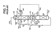
- Figure 7 shows a prior art pump-back cycle similar to that disclosed in US-A-5,964,104 (Rottmann).
- the nitrogen product streams 109, 133, and 155 each have been described as having a pressure equal to that of the corresponding column for the stream.
- the pressures of these streams may be changed before being delivered as product. Examples include but are not limited to: 1) pressure increased in a compressor, 2) pressure decreased in an expander, 3) pressure decreased in a throttling device, and 4) pressure decreased in a turboejector.
- Refrigeration for the process has not been illustrated in the examples given, as this is not required to describe the essence of the invention. Persons skilled in the art will recognize that many alternate refrigeration means exist. Examples include but are not limited to: 1) expansion of a portion of the air component vapor stream 101 to the higher-pressure column 103, 2) expansion of a portion of the air component vapor stream 101 to the lower-pressure column 121, 3) expansion of a portion of the secondary air component vapor stream 151 to the supplemental column 149, and 4) expansion of a vapor from columns 103, 121, and 149, such as a portion of a nitrogen product.
- the reflux, or top feed, for the lower-pressure column 121 is shown as stream 139.
- Other optional reflux streams exist. Examples include but are not limited to: 1) a liquid from an intermediate location of the higher-pressure column 103; and 2) a portion of liquid stream 407 liquid from the top of the supplemental column 149. In such an event, stream 139 may or may not be optionally required.
- processing steps may exist before any stream is fed to a column.
- there may be multiple processing steps such as sending a first nitrogen-enriched stream to the higher-pressure column, withdrawing a second nitrogen-enriched stream from the higher-pressure column, and sending the second nitrogen-enriched stream to the supplemental column.
- the second nitrogen-enriched stream may be withdrawn from the higher-pressure column at the same stage where the first nitrogen-enriched stream is fed to that column or at multiple stages above or below that feed location.
- stream 153 is sent to the bottom of the higher-pressure column 103. Further, only a single enriched nitrogen product is produced, stream 155, at a pressure of 302 psia (2080 kPa). Flows and conditions for major streams can be found in Table 1.
- the prior art requires higher column pressures in the distillation unit than does the invention. Since higher-pressure columns tend to require thicker, more costly materials, the invention allows for a reduction of the costs involved with the distillation unit. Further, less feed air is required in the invention. Primarily, a large portion of the feed air, 67.5%, does not pass through the higher-pressure column 103; instead, it is sent directly to the supplemental column 149. Secondly, the prior art is able to extract about 63% of the nitrogen entering as feed air, while the invention is able to extract about 75%. The air fed to the higher-pressure column 103 is of a much lower flow and a lower pressure.
Landscapes
- Engineering & Computer Science (AREA)
- Physics & Mathematics (AREA)
- Mechanical Engineering (AREA)
- Thermal Sciences (AREA)
- General Engineering & Computer Science (AREA)
- Power Engineering (AREA)
- Separation By Low-Temperature Treatments (AREA)
Abstract
Description


Claims (25)
- A process for separating a multi-component fluid comprising oxygen and nitrogen to produce nitrogen, said process using a distillation column system having at least three distillation columns, including a higher-pressure column operating at a first pressure, a lower-pressure column operating at a second pressure lower than the first pressure, and a supplemental column operating at a third pressure greater than or equal to the second pressure, optionally wherein the higher-pressure column and the lower-pressure column are thermally linked through a first heat exchanger, comprising:wherein at least a portion of the reflux for the supplemental column is provided by the condensed first nitrogen-rich vapor stream or is otherwise derived from the higher pressure or lower pressure column.feeding a first stream of the multi-component fluid to the higher-pressure column;feeding a second stream of the multi-component fluid or another multi-component fluid compromising oxygen and nitrogen to the supplemental column;withdrawing a first nitrogen-rich vapor stream from the higher-pressure column or the lower-pressure column;withdrawing a first oxygen-rich liquid stream from the lower-pressure column;heat exchanging at least a portion of the first oxygen-rich liquid stream indirectly against at least a portion of the first nitrogen-rich vapor stream in the first heat exchanger or a second heat exchanger, thereby at least partially vaporizing the first oxygen-rich liquid stream and at least partially condensing the first nitrogen-rich vapor stream;changing the pressure of at least a portion of the condensed first nitrogen-rich vapor stream;feeding at least a portion of the condensed first nitrogen-rich vapor stream to the higher pressure column, lower pressure column or supplemental column;withdrawing a second oxygen-rich liquid stream from the supplemental column;feeding at least a portion of the second oxygen-rich liquid stream to the lower-pressure column or the higher-pressure column; andwithdrawing a first stream of nitrogen product from the supplemental column, and
- A process as claimed in Claim 1 for separating a multi-component fluid comprising oxygen and nitrogen to produce nitrogen, said process using a distillation column system having at least three distillation columns, including a higher-pressure column operating at a first pressure, a lower-pressure column operating at a second pressure lower than the first pressure, and a supplemental column operating at a third pressure greater than or equal to the second pressure, wherein the higher-pressure column and the lower-pressure column are thermally linked through a first heat exchanger, comprising:feeding a first stream of the multi-component fluid to the higher-pressure column;feeding a second stream of the multi-component fluid or another multi-component fluid compromising oxygen and nitrogen to the supplemental column;withdrawing a first nitrogen-rich vapor stream from the higher-pressure column or the lower-pressure column;withdrawing a first oxygen-rich liquid stream from the lower-pressure column;heat exchanging at least a portion of the first oxygen-rich liquid stream indirectly against at least a portion of the first nitrogen-rich vapor stream in the first heat exchanger or a second heat exchanger, thereby at least partially vaporizing the first oxygen-rich liquid stream and at least partially condensing the first nitrogen-rich vapor stream;changing the pressure of at least a portion of the condensed first nitrogen-rich vapor stream;feeding at least a portion of the condensed first nitrogen-rich vapor stream to the supplemental column;withdrawing a second oxygen-rich liquid stream from the supplemental column;feeding at least a portion of the second oxygen-rich liquid stream to the lower-pressure column or the higher-pressure column; andwithdrawing a first stream of nitrogen product from the supplemental column.
- A process as claimed in Claim 1 or Claim 2, wherein the pressure of the portion of the condensed first nitrogen-rich vapor stream is changed by increasing the pressure.
- A process as claimed in any one of Claims 1 to 3, wherein a first portion of the first nitrogen-rich vapor stream is withdrawn from the higher pressure column and at least a portion thereof condensed in the first heat exchanger to provide a first portion of the condensed first nitrogen-rich vapor stream and a second portion of the first nitrogen-rich vapor stream is withdrawn from the lower pressure column and at least a portion thereof condensed in the second heat exchanger to provide a second portion of the condensed nitrogen-rich vapor stream.
- A process as claimed in Claim 4, wherein at least the second portion of the condensed nitrogen-rich vapor stream is increased in pressure before feeding to the supplemental column.
- A process as claimed in any one of Claims 1 to 3, wherein the first nitrogen-rich vapor stream is withdrawn from the higher pressure column and at least a portion thereof condensed in the second heat exchanger to provide the condensed first nitrogen-rich vapor stream.
- A process as claimed in Claim 3, wherein the first nitrogen-rich vapor stream is withdrawn from the lower pressure column and at least a portion thereof condensed in the second heat exchanger to provide the condensed first nitrogen-rich vapor stream.
- A process as claimed in Claim 3, further comprising:withdrawing a second nitrogen-rich vapor stream from the supplemental column;withdrawing a third oxygen-rich liquid stream from the lower-pressure column;heat exchanging at least a portion of the third oxygen-rich liquid stream indirectly against at least a portion of the second nitrogen-rich vapor stream in a third heat exchanger, thereby at least partially condensing the second nitrogen-rich vapor-stream; andfeeding at least a portion of the condensed second nitrogen-rich vapor stream to the supplemental column.
- A process as claimed in Claim 8, wherein:a portion of the condensed first nitrogen-rich vapor stream is fed to the supplemental column at a first location; anda portion of the condensed second nitrogen-rich vapor stream is fed to the supplemental column at the first location or at a second location above the first location.
- A process as claimed in Claim 8 or Claim 9, wherein the first nitrogen-rich vapor stream is withdrawn from the lower pressure column and at least a portion thereof condensed in the second heat exchanger to provide the condensed first nitrogen-rich vapor stream.
- A process as claimed in Claim 1 or Claim 2, wherein the pressure of the portion of the condensed first nitrogen-rich vapor stream is changed by reducing the pressure.
- A process as claimed in Claim 11, wherein the first nitrogen-rich vapor stream is withdrawn from the higher pressure column and a portion thereof condensed in the first heat exchanger.
- A process as claimed in Claim 11 or Claim 12, further comprising:withdrawing a second nitrogen-rich vapor stream from the lower-pressure column;withdrawing a third oxygen-rich liquid stream from the lower-pressure column;heat exchanging at least a portion of the third oxygen-rich liquid stream indirectly against at least a portion of the second nitrogen-rich vapor stream in a second heat exchanger, thereby at least partially condensing the second nitrogen-rich vapor-stream;increasing the pressure of at least a portion of the condensed second nitrogen-rich vapor stream; andfeeding at least a portion of the condensed second nitrogen-rich vapor stream to the higher-pressure column.
- A process as claimed in any one of Claims 1 to 10, wherein the third pressure is greater than or equal to the first pressure.
- A process as claimed in any one of the preceding claims, wherein the second oxygen-rich liquid stream is fed to the lower pressure column.
- A process as claimed in Claim 14, wherein the second oxygen-rich liquid stream is fed to the higher pressure column.
- A process as claimed in any one of the preceding claims, wherein:a first nitrogen-rich liquid stream from the first heat exchanger is fed to the lower-pressure column at a first location; anda second nitrogen-rich liquid stream from the second heat exchanger is fed to the lower-pressure column at a second location above the first location.
- A process for the preparation of a nitrogen product by cryogenic distillation of multi-component fluid comprising oxygen and nitrogen within a distillation column system that contains at least a distillation unit, which comprises at least a lower-pressure column and a higher-pressure column, and a supplemental column, in which the pressure is at least equal to the pressure of the lower-pressure column, wherein:a liquid stream enriched in oxygen is withdrawn from the lower-pressure column and vaporized through indirect latent heat transfer to produce a reflux stream;a portion of the reflux stream is sent to the lower-pressure column, the higher-pressure column, and/or the supplemental column;at least a portion of the reflux for the supplemental column is derived from the distillation unit;a nitrogen enriched liquid removed from the distillation unit is raised in pressure and is sent to either the supplemental column or returned to the distillation unit;an oxygen-enriched fluid from the bottom of the supplemental column is sent to the distillation unit; andat least a portion of the nitrogen product is removed from the supplemental column.
- A process as claimed in Claim 18, wherein the reflux stream is a condensed nitrogen-rich vapor stream generated in the distillation unit.
- A process as claimed in any one of the preceding claims, comprising withdrawing a stream of a product enriched in nitrogen from the lower-pressure column.
- A process as claimed in any one of the preceding claims, further comprising withdrawing a stream of product enriched in nitrogen from the higher-pressure column.
- A process as claimed in any one of the preceding claims, wherein the multi-component fluid is air.
- An apparatus for separating a multi-component fluid comprising oxygen and nitrogen to produce nitrogen by a process as defined in Claim 2, said apparatus comprising:a distillation column system having at least three distillation columns, including:a higher-pressure column (103) for operating at a first pressure,a lower-pressure column (121) for operating at a second pressure lower than the first pressure,a supplemental column (149) for operating at a third pressure greater than or equal to the second pressure, anda first heat exchanger (113) for thermally linking the higher-pressure column (103) and the lower-pressure column (121):conduit means (101) for feeding a first stream of the multi-component fluid to the higher-pressure column (103);conduit means (151) for feeding a second stream of the multi-component fluid or another multi-component fluid compromising oxygen and nitrogen to the supplemental column (149);conduit means (107, 125) for withdrawing a first nitrogen-rich vapor stream from the higher-pressure column (103) or the lower-pressure column (121);conduit means (123) for withdrawing a first oxygen-rich liquid stream from the lower-pressure column (121);optionally, a second heat exchanger (129) for heat exchanging at least a portion of the first oxygen-rich liquid stream indirectly against at least a portion of the first nitrogen-rich vapor stream;pressure changing means (145) for changing the pressure of at least a portion of a condensed first nitrogen-rich vapor stream from the first or second heat exchanger (113, 129);conduit means (147) for feeding at least a portion of the condensed first nitrogen-rich vapor stream to the supplemental column (103);conduit means (153) for withdrawing a second oxygen-rich liquid stream from the supplemental column (149) and feeding at least a portion of the second oxygen-rich liquid stream to the lower-pressure column (121) or the higher-pressure column (103); andconduit means (155) for withdrawing a first stream of nitrogen product from the supplemental column (149).
- An apparatus for the preparation of a nitrogen product by cryogenic distillation of multi-component fluid comprising oxygen and nitrogen by a process as defined in Claim 18, said apparatus comprising:a distillation column system that contains at least a distillation unit, which comprises at least a lower-pressure column (121) and a higher-pressure column (103), and a supplemental column (149) for operating at a pressure is at least equal to the pressure of the lower-pressure column (121);conduit means (123) for withdrawing a liquid stream enriched in oxygen from the lower-pressure column;a heat exchanger (113) for vaporizing the oxygen-enriched liquid stream through indirect latent heat transfer with a nitrogen-enriched vapor stream to produce a reflux stream;conduit means (119 & 139; 117; 119, 143 &147) for sending a portion of the reflux stream to the lower-pressure column (121), the higher-pressure column (103), and/or the supplemental column (149);at least when said conduit means (119, 143 & 147) does not send a portion of said reflux stream to the supplemental column (149), reflux means for providing a portion of the reflux for the supplemental column from the distillation unit;pressure-increasing means (145) for raising the pressure of a nitrogen enriched liquid removed from the distillation unit;conduit means (147; 501) for sending said pressure-increased stream to the supplemental column (149) or to the distillation unit (103, 121);conduit means (153) for sending an oxygen-enriched fluid from the bottom of the supplemental column (149) to the distillation unit (103, 121); andconduit means (155) for removing as product at least a portion of the nitrogen product from the supplemental column (149).
- An apparatus as claimed in Claim 23 or Claim 24, which is a cryogenic air separation unit .
Applications Claiming Priority (2)
| Application Number | Priority Date | Filing Date | Title |
|---|---|---|---|
| US879232 | 2001-06-12 | ||
| US09/879,232 US6397631B1 (en) | 2001-06-12 | 2001-06-12 | Air separation process |
Publications (2)
| Publication Number | Publication Date |
|---|---|
| EP1271081A2 true EP1271081A2 (en) | 2003-01-02 |
| EP1271081A3 EP1271081A3 (en) | 2003-02-12 |
Family
ID=25373693
Family Applications (1)
| Application Number | Title | Priority Date | Filing Date |
|---|---|---|---|
| EP02254046A Withdrawn EP1271081A3 (en) | 2001-06-12 | 2002-06-11 | Air seperation process |
Country Status (2)
| Country | Link |
|---|---|
| US (1) | US6397631B1 (en) |
| EP (1) | EP1271081A3 (en) |
Cited By (4)
| Publication number | Priority date | Publication date | Assignee | Title |
|---|---|---|---|---|
| EP1363093A1 (en) * | 2002-05-01 | 2003-11-19 | Air Products And Chemicals, Inc. | Nitrogen generation process |
| EP1653183A1 (en) * | 2004-10-12 | 2006-05-03 | Air Products And Chemicals, Inc. | Process and device for the cryogenic distillation of air |
| EP1318367B1 (en) * | 2001-12-04 | 2007-03-07 | Air Products And Chemicals, Inc. | Process and apparatus for the cryogenic separation of air |
| CN102901322A (en) * | 2011-07-26 | 2013-01-30 | 林德股份公司 | Method and device for extracting pressurised oxygen and pressurised nitrogen by cryogenic decomposition of air |
Families Citing this family (7)
| Publication number | Priority date | Publication date | Assignee | Title |
|---|---|---|---|---|
| US8640496B2 (en) * | 2008-08-21 | 2014-02-04 | Praxair Technology, Inc. | Method and apparatus for separating air |
| US9103587B2 (en) * | 2009-12-17 | 2015-08-11 | L'Air Liquide Société Anonyme pour l'Etude et l'Exploitation des Procedes Georges Claude | Process and apparatus for the separation of air by cryogenic distillation |
| US20130000351A1 (en) * | 2011-06-28 | 2013-01-03 | Air Liquide Process & Construction, Inc. | Production Of High-Pressure Gaseous Nitrogen |
| US9097459B2 (en) | 2011-08-17 | 2015-08-04 | Air Liquide Process & Construction, Inc. | Production of high-pressure gaseous nitrogen |
| MX2015008172A (en) * | 2012-12-27 | 2015-09-16 | Linde Ag | Method and device for low-temperature air separation. |
| US20250290692A1 (en) * | 2024-03-18 | 2025-09-18 | Air Products And Chemicals, Inc. | Apparatus and process for providing nitrogen and oxygen |
| DE102024001541A1 (en) * | 2024-05-11 | 2025-11-13 | Linde Gmbh | Air separation plant with special spatial arrangement and process for low-temperature air separation |
Family Cites Families (22)
| Publication number | Priority date | Publication date | Assignee | Title |
|---|---|---|---|---|
| DE1922956B1 (en) | 1969-05-06 | 1970-11-26 | Hoechst Ag | Process for the production of argon-free oxygen by the rectification of air |
| GB2057660B (en) | 1979-05-17 | 1983-03-16 | Union Carbide Corp | Process and apparatus for producing low purity oxygen |
| US4605427A (en) | 1983-03-31 | 1986-08-12 | Erickson Donald C | Cryogenic triple-pressure air separation with LP-to-MP latent-heat-exchange |
| US4533375A (en) | 1983-08-12 | 1985-08-06 | Erickson Donald C | Cryogenic air separation with cold argon recycle |
| US4582518A (en) | 1984-09-26 | 1986-04-15 | Erickson Donald C | Nitrogen production by low energy distillation |
| US5069699A (en) | 1990-09-20 | 1991-12-03 | Air Products And Chemicals, Inc. | Triple distillation column nitrogen generator with plural reboiler/condensers |
| US5471843A (en) * | 1993-06-18 | 1995-12-05 | L'air Liquide, Societe Anonyme Pour L'etude Et L'exploitation Des Procedes Georges Claude | Process and installation for the production of oxygen and/or nitrogen under pressure at variable flow rate |
| GB9325648D0 (en) | 1993-12-15 | 1994-02-16 | Boc Group Plc | Air separation |
| US5402647A (en) | 1994-03-25 | 1995-04-04 | Praxair Technology, Inc. | Cryogenic rectification system for producing elevated pressure nitrogen |
| DE19537913A1 (en) | 1995-10-11 | 1997-04-17 | Linde Ag | Triple column process for the low temperature separation of air |
| JP3667889B2 (en) | 1996-08-16 | 2005-07-06 | 大陽日酸株式会社 | Nitrogen production method and apparatus |
| DE19735154A1 (en) | 1996-10-30 | 1998-05-07 | Linde Ag | Producing compressed nitrogen@ by low temperature distillation of air in rectifier system |
| DE19720453A1 (en) | 1997-05-15 | 1998-11-19 | Linde Ag | Process and device for the production of nitrogen by low-temperature separation of air |
| GB9724787D0 (en) * | 1997-11-24 | 1998-01-21 | Boc Group Plc | Production of nitrogen |
| GB9726954D0 (en) | 1997-12-19 | 1998-02-18 | Wickham Michael | Air separation |
| US5918482A (en) | 1998-02-17 | 1999-07-06 | Praxair Technology, Inc. | Cryogenic rectification system for producing ultra-high purity nitrogen and ultra-high purity oxygen |
| US5906113A (en) | 1998-04-08 | 1999-05-25 | Praxair Technology, Inc. | Serial column cryogenic rectification system for producing high purity nitrogen |
| FR2778234B1 (en) * | 1998-04-30 | 2000-06-02 | Air Liquide | AIR DISTILLATION SYSTEM AND CORRESPONDING COLD BOX |
| WO2000060294A1 (en) | 1999-04-05 | 2000-10-12 | L'air Liquide Societe Anonyme Pour L'etude Et L'exploitation Des Procedes Georges Claude | Variable capacity fluid mixture separation apparatus and process |
| US6276171B1 (en) | 1999-04-05 | 2001-08-21 | L'air Liquide, Societe Anonyme Pour L'etude Et L'exploitation Des Procedes Georges Claude | Integrated apparatus for generating power and/or oxygen enriched fluid, process for the operation thereof |
| US6116052A (en) * | 1999-04-09 | 2000-09-12 | Air Liquide Process And Construction | Cryogenic air separation process and installation |
| DE19933558C5 (en) * | 1999-07-16 | 2010-04-15 | Linde Ag | Three-column process and apparatus for the cryogenic separation of air |
-
2001
- 2001-06-12 US US09/879,232 patent/US6397631B1/en not_active Expired - Fee Related
-
2002
- 2002-06-11 EP EP02254046A patent/EP1271081A3/en not_active Withdrawn
Cited By (6)
| Publication number | Priority date | Publication date | Assignee | Title |
|---|---|---|---|---|
| EP1318367B1 (en) * | 2001-12-04 | 2007-03-07 | Air Products And Chemicals, Inc. | Process and apparatus for the cryogenic separation of air |
| EP1318367B2 (en) † | 2001-12-04 | 2009-11-11 | Air Products And Chemicals, Inc. | Process and apparatus for the cryogenic separation of air |
| EP1363093A1 (en) * | 2002-05-01 | 2003-11-19 | Air Products And Chemicals, Inc. | Nitrogen generation process |
| EP1653183A1 (en) * | 2004-10-12 | 2006-05-03 | Air Products And Chemicals, Inc. | Process and device for the cryogenic distillation of air |
| CN102901322A (en) * | 2011-07-26 | 2013-01-30 | 林德股份公司 | Method and device for extracting pressurised oxygen and pressurised nitrogen by cryogenic decomposition of air |
| CN102901322B (en) * | 2011-07-26 | 2016-08-10 | 林德股份公司 | Pressure nitrogen and the method and apparatus of pressure oxygen is obtained by Cryogenic air separation |
Also Published As
| Publication number | Publication date |
|---|---|
| EP1271081A3 (en) | 2003-02-12 |
| US6397631B1 (en) | 2002-06-04 |
Similar Documents
| Publication | Publication Date | Title |
|---|---|---|
| EP0697576B1 (en) | Air separation method and apparatus | |
| US5396773A (en) | Process for the mixed production of high and low purity oxygen | |
| EP0636845B1 (en) | Air separation | |
| JP2002327981A (en) | Cryogenic air-separation method of three-tower type | |
| EP0558082A1 (en) | Cryogenic rectification system with argon heat pump | |
| JP2836781B2 (en) | Air separation method | |
| JP2762026B2 (en) | Cryogenic rectification unit with thermally integrated argon column | |
| EP0766053B1 (en) | Cryogenic rectification system for producing dual purity oxygen | |
| JPH0694361A (en) | Separation of air | |
| US6279345B1 (en) | Cryogenic air separation system with split kettle recycle | |
| US6397631B1 (en) | Air separation process | |
| US5467602A (en) | Air boiling cryogenic rectification system for producing elevated pressure oxygen | |
| US5628207A (en) | Cryogenic Rectification system for producing lower purity gaseous oxygen and high purity oxygen | |
| US5385024A (en) | Cryogenic rectification system with improved recovery | |
| EP0563800A1 (en) | High recovery cryogenic rectification system | |
| EP0848218B1 (en) | Cryogenic rectification system for producing lower purity oxygen and higher purity oxygen | |
| EP0418139B1 (en) | Cryogenic air separation process and apparatus | |
| JP2865281B2 (en) | Low temperature distillation method of air raw material | |
| US5144808A (en) | Cryogenic air separation process and apparatus | |
| EP0615105B1 (en) | Air separation | |
| EP0780647A2 (en) | Cryogenic rectification system with nitrogen turboexpander heat pump | |
| JP2000356465A (en) | Low-temperature distillating system for separating air | |
| US6279344B1 (en) | Cryogenic air separation system for producing oxygen | |
| US5682765A (en) | Cryogenic rectification system for producing argon and lower purity oxygen | |
| EP1271080A1 (en) | Medium-pressure nitrogen production with high oxygen recovery |
Legal Events
| Date | Code | Title | Description |
|---|---|---|---|
| PUAI | Public reference made under article 153(3) epc to a published international application that has entered the european phase |
Free format text: ORIGINAL CODE: 0009012 |
|
| PUAL | Search report despatched |
Free format text: ORIGINAL CODE: 0009013 |
|
| AK | Designated contracting states |
Kind code of ref document: A2 Designated state(s): AT BE CH CY DE DK ES FI FR GB GR IE IT LI LU MC NL PT SE TR |
|
| AX | Request for extension of the european patent |
Free format text: AL;LT;LV;MK;RO;SI |
|
| AK | Designated contracting states |
Designated state(s): AT BE CH CY DE DK ES FI FR GB GR IE IT LI LU MC NL PT SE TR |
|
| AX | Request for extension of the european patent |
Extension state: AL LT LV MK RO SI |
|
| 17P | Request for examination filed |
Effective date: 20030327 |
|
| AKX | Designation fees paid |
Designated state(s): AT BE CH CY DE DK ES FI FR GB GR IE IT LI LU MC NL PT SE TR |
|
| 17Q | First examination report despatched |
Effective date: 20060621 |
|
| STAA | Information on the status of an ep patent application or granted ep patent |
Free format text: STATUS: THE APPLICATION IS DEEMED TO BE WITHDRAWN |
|
| 18D | Application deemed to be withdrawn |
Effective date: 20100105 |