EP1271071A1 - Method of controlling preheating power and mechanism for providing preheating - Google Patents
Method of controlling preheating power and mechanism for providing preheating Download PDFInfo
- Publication number
- EP1271071A1 EP1271071A1 EP01915797A EP01915797A EP1271071A1 EP 1271071 A1 EP1271071 A1 EP 1271071A1 EP 01915797 A EP01915797 A EP 01915797A EP 01915797 A EP01915797 A EP 01915797A EP 1271071 A1 EP1271071 A1 EP 1271071A1
- Authority
- EP
- European Patent Office
- Prior art keywords
- motor
- preheating
- phase
- voltage
- inverter
- Prior art date
- Legal status (The legal status is an assumption and is not a legal conclusion. Google has not performed a legal analysis and makes no representation as to the accuracy of the status listed.)
- Ceased
Links
Images



Classifications
-
- H—ELECTRICITY
- H02—GENERATION; CONVERSION OR DISTRIBUTION OF ELECTRIC POWER
- H02P—CONTROL OR REGULATION OF ELECTRIC MOTORS, ELECTRIC GENERATORS OR DYNAMO-ELECTRIC CONVERTERS; CONTROLLING TRANSFORMERS, REACTORS OR CHOKE COILS
- H02P27/00—Arrangements or methods for the control of AC motors characterised by the kind of supply voltage
- H02P27/02—Arrangements or methods for the control of AC motors characterised by the kind of supply voltage using supply voltage with constant frequency and variable amplitude
- H02P27/024—Arrangements or methods for the control of AC motors characterised by the kind of supply voltage using supply voltage with constant frequency and variable amplitude using AC supply for only the rotor circuit or only the stator circuit
-
- F—MECHANICAL ENGINEERING; LIGHTING; HEATING; WEAPONS; BLASTING
- F24—HEATING; RANGES; VENTILATING
- F24F—AIR-CONDITIONING; AIR-HUMIDIFICATION; VENTILATION; USE OF AIR CURRENTS FOR SCREENING
- F24F11/00—Control or safety arrangements
- F24F11/70—Control systems characterised by their outputs; Constructional details thereof
- F24F11/80—Control systems characterised by their outputs; Constructional details thereof for controlling the temperature of the supplied air
- F24F11/83—Control systems characterised by their outputs; Constructional details thereof for controlling the temperature of the supplied air by controlling the supply of heat-exchange fluids to heat-exchangers
-
- F—MECHANICAL ENGINEERING; LIGHTING; HEATING; WEAPONS; BLASTING
- F24—HEATING; RANGES; VENTILATING
- F24F—AIR-CONDITIONING; AIR-HUMIDIFICATION; VENTILATION; USE OF AIR CURRENTS FOR SCREENING
- F24F11/00—Control or safety arrangements
- F24F11/89—Arrangement or mounting of control or safety devices
-
- H—ELECTRICITY
- H02—GENERATION; CONVERSION OR DISTRIBUTION OF ELECTRIC POWER
- H02P—CONTROL OR REGULATION OF ELECTRIC MOTORS, ELECTRIC GENERATORS OR DYNAMO-ELECTRIC CONVERTERS; CONTROLLING TRANSFORMERS, REACTORS OR CHOKE COILS
- H02P29/00—Arrangements for regulating or controlling electric motors, appropriate for both AC and DC motors
- H02P29/60—Controlling or determining the temperature of the motor or of the drive
- H02P29/62—Controlling or determining the temperature of the motor or of the drive for raising the temperature of the motor
-
- F—MECHANICAL ENGINEERING; LIGHTING; HEATING; WEAPONS; BLASTING
- F24—HEATING; RANGES; VENTILATING
- F24F—AIR-CONDITIONING; AIR-HUMIDIFICATION; VENTILATION; USE OF AIR CURRENTS FOR SCREENING
- F24F11/00—Control or safety arrangements
- F24F11/30—Control or safety arrangements for purposes related to the operation of the system, e.g. for safety or monitoring
- F24F11/46—Improving electric energy efficiency or saving
-
- F—MECHANICAL ENGINEERING; LIGHTING; HEATING; WEAPONS; BLASTING
- F24—HEATING; RANGES; VENTILATING
- F24F—AIR-CONDITIONING; AIR-HUMIDIFICATION; VENTILATION; USE OF AIR CURRENTS FOR SCREENING
- F24F11/00—Control or safety arrangements
- F24F11/70—Control systems characterised by their outputs; Constructional details thereof
- F24F11/80—Control systems characterised by their outputs; Constructional details thereof for controlling the temperature of the supplied air
- F24F11/83—Control systems characterised by their outputs; Constructional details thereof for controlling the temperature of the supplied air by controlling the supply of heat-exchange fluids to heat-exchangers
- F24F11/85—Control systems characterised by their outputs; Constructional details thereof for controlling the temperature of the supplied air by controlling the supply of heat-exchange fluids to heat-exchangers using variable-flow pumps
-
- F—MECHANICAL ENGINEERING; LIGHTING; HEATING; WEAPONS; BLASTING
- F25—REFRIGERATION OR COOLING; COMBINED HEATING AND REFRIGERATION SYSTEMS; HEAT PUMP SYSTEMS; MANUFACTURE OR STORAGE OF ICE; LIQUEFACTION SOLIDIFICATION OF GASES
- F25B—REFRIGERATION MACHINES, PLANTS OR SYSTEMS; COMBINED HEATING AND REFRIGERATION SYSTEMS; HEAT PUMP SYSTEMS
- F25B2600/00—Control issues
- F25B2600/02—Compressor control
- F25B2600/021—Inverters therefor
-
- F—MECHANICAL ENGINEERING; LIGHTING; HEATING; WEAPONS; BLASTING
- F25—REFRIGERATION OR COOLING; COMBINED HEATING AND REFRIGERATION SYSTEMS; HEAT PUMP SYSTEMS; MANUFACTURE OR STORAGE OF ICE; LIQUEFACTION SOLIDIFICATION OF GASES
- F25B—REFRIGERATION MACHINES, PLANTS OR SYSTEMS; COMBINED HEATING AND REFRIGERATION SYSTEMS; HEAT PUMP SYSTEMS
- F25B2700/00—Sensing or detecting of parameters; Sensors therefor
- F25B2700/15—Power, e.g. by voltage or current
-
- Y—GENERAL TAGGING OF NEW TECHNOLOGICAL DEVELOPMENTS; GENERAL TAGGING OF CROSS-SECTIONAL TECHNOLOGIES SPANNING OVER SEVERAL SECTIONS OF THE IPC; TECHNICAL SUBJECTS COVERED BY FORMER USPC CROSS-REFERENCE ART COLLECTIONS [XRACs] AND DIGESTS
- Y02—TECHNOLOGIES OR APPLICATIONS FOR MITIGATION OR ADAPTATION AGAINST CLIMATE CHANGE
- Y02B—CLIMATE CHANGE MITIGATION TECHNOLOGIES RELATED TO BUILDINGS, e.g. HOUSING, HOUSE APPLIANCES OR RELATED END-USER APPLICATIONS
- Y02B30/00—Energy efficient heating, ventilation or air conditioning [HVAC]
- Y02B30/70—Efficient control or regulation technologies, e.g. for control of refrigerant flow, motor or heating
Definitions
- the present invention relates to a motor and especially to a technique for maintaining constant power consumption in preheating a compressor motor in an air conditioner. It also relates to a technique for preheating a compressor motor driven by a pulse-width modulation inverter.
- lubricating oil has been employed for reducing friction at a motor bearing. This technique is also employed in compressor motors in air conditioners.
- the compressor motors in air conditioners in particular handle refrigerant and have the characteristic that at low temperatures, the refrigerant is soluble in refrigeration oil which is lubricating oil. When driven at low temperatures, the compressor motors in air conditioners rotate with the refrigeration oil in small concentrations. Thus, there is a high possibility that sliding portions of the compressors will seize up by friction.
- the technique in which the inverter supplies current on the above condition so that the compressor motor preheats itself has a problem of being highly susceptible to variations in supply power. For example if the current waveform is determined to give 35W of power consumption by preheating for a receiving voltage of 200 V, an increase of the receiving voltage to 220 V increases the power consumption by preheating to approximately 42 W, i.e., by a factor of (220/200) 2 . This results in excessive power consumption. A decrease of the receiving voltage to 180 V, on the other hand, reduces the power consumption by preheating to approximately 28 W, i.e., by a factor of (180/200) 2 . This results in insufficient preheating and thereby raises the possibility that the solubility of refrigeration oil in refrigerant cannot be reduced sufficiently.
- the present invention has been made in view of the above circumstances and provides a technique for permitting constant preheating of a motor irrespective of variations in receiving voltage.
- the present invention also provides a technique for giving constant preheating power irrespective of a temperature of a coil of a motor.
- a first aspect of the present invention is directed to a method of controlling preheating power, the method controlling preheating of a coil (L U , L W ) of a polyphase motor (30), wherein the polyphase motor is operated open-phase to generate heat.
- the polyphase motor is driven by an inverter (15), the inverter applying current to the coil (L U , L W ) for the preheating of the polyphase motor, the current being applied with a predetermined period (T) from the inverter to the polyphase motor, on a condition that the polyphase motor should not be rotated, and as a DC voltage (Vm) applied to the inverter increases, a duty (D) which is the ratio between time during which the voltage is applied to the coil and the period, is set to a smaller value.
- Vm DC voltage
- D which is the ratio between time during which the voltage is applied to the coil and the period
- the current in the method of controlling preheating power according to the second aspect, the current produces no revolving field for the polyphase motor in preheating the polyphase motor.
- the polyphase motor is a compressor motor in an air conditioner.
- the polyphase motor is a three-phase motor
- the inverter is a three-phase inverter, each phase having a pair of positive and negative switching elements (Q U , Q V , Q W , Q X , Q Y , Q Z ), and the period includes: a first period (t on ) during which the positive switching element (Q U ) in a first phase (U) is in the on state, the negative switching element (Q Z ) in a second phase (W) is in the on state, and the positive and negative switching elements (Q V ; Q Y ) in a third phase (V) are complementarily in the on state for an equal length of time; and a second period (t off ) during which, in all of the first, second, and third phases, either the positive switching elements (Q U , Q V , Q W ) are in the on state or the negative switching elements (Q X , Q Y
- the duty is set to a value obtained by dividing a product of a known calibrated voltage (V ref ), a known calibrated current (I ref ), and a known calibrated duty (D 0 ) by a product of a current (I m ) and a voltage (V m ) applied to the motor.
- the duty is set to a larger value as a temperature of the polyphase motor increases.
- the preheating is performed on refrigeration oil in a compressor.
- a ninth aspect of the present invention is directed to a preheating system comprising: a polyphase motor (30) having coils (L U , L W ); and an operation control unit for operating the polyphase motor open-phase to generate heat.
- the operation control unit includes an inverter (15), the inverter applying current to the polyphase motor with a predetermined period (T), on a condition that the polyphase motor should not be rotated, and as a DC voltage (Vm) applied to the inverter increases, a duty (D) which is the ratio between time during which the voltage is applied to the coil and the period, is set to a smaller value.
- the current in the preheating system according to the tenth aspect, produces no revolving field for the polyphase motor.
- the polyphase motor is a compressor motor in an air conditioner.
- the polyphase motor is a three-phase motor
- the inverter is a three-phase inverter, each phase having a pair of positive and negative switching elements (Q U , Q V , Q W , Q X , Q Y , Q Z ), and the period includes: a first period (t on ) during which the positive switching element (Q U ) in a first phase (U) is in the on state, the negative switching element (Q Z ) in a second phase (W) is in the on state, and the positive and negative switching elements (Q V ; Q Y ) in a third phase (V) are complementarily in the on state for an equal length of time; and a second period (t off ) during which, in all of the first, second, and third phases, either the positive switching elements (Q U , Q V , Q W ) are in the on state or the negative switching elements (Q X , Q Y
- the duty is set to a value obtained by dividing a product of a known calibrated voltage (V ref ), a known calibrated current (I ref ), and a known duty (D 0 ) by a product of a current (Im) and a voltage (Vm) applied to the motor.
- the duty is set to a larger value as a temperature of the polyphase motor increases.
- the preheating is performed on refrigeration oil in a compressor.
- the polyphase motor is operated open-phase to generate heat and thereby to be preheated.
- preheating can be achieved with predetermined power irrespective of the variations in the DC voltage. This avoids excess power consumption and insufficient preheating.
- the polyphase motor can be preheated without being rotated. This prevents the occurrence of such mutually contradictory phenomena that heat generation causes the bearing to be worn out. Besides, the generation of sound can be minimized because a so-called "slip" is not utilized which is a phenomenon that the revolving field is produced but the motor is not rotated.
- the solubility of lubricating oil in refrigerant which is handled by the compression motor in the air conditioner can be reduced. This prevents a situation in which, with refrigeration oil which is lubricating oil being dissolved in refrigerant and reduced in concentration, the motor is rotated and thereby the bearing will seize up by friction.
- the positive and negative switching elements in the third phase are complementarily in the on state for an equal length of time; therefore, substantially no current flows to the coil in the third phase in the polyphase motor.
- the inductance of the coils in the first and second phases in the motor maintains the current flow occurring during the first period. Accordingly, current continues to flow in the same direction to the series connection of the coils in the first and second phases, which allows almost constant current to continuously flow to the motor without generating a revolving field.
- the duty is the value obtained by dividing desired power by the product of current and voltage applied to the motor. This allows constant preheating power to be given irrespective of the values of current and voltage applied to the motor.
- preheating power can be increased by increasing the duty. Accordingly, the preheating power can be set to a desired value irrespective of the temperature of the polyphase motor.
- refrigeration oil is hardly soluble in refrigerant and thus the motor can be prevented from being rotated with the refrigeration oil reduced in concentration. This prevents a sliding portion of the compressor from seizing up by friction.
- Fig. 1 is a circuit diagram illustrating a compressor motor 30 and its driving circuit in an air conditioner, to which a control method according to a first embodiment of the present invention is applied.
- a voltage supplied from a three-phase AC power supply 10 is converted into a DC current with a ripple by a diode bridge 11 of a well-known configuration.
- the DC current is then passed through, for example, a choke input filter and a DC voltage is applied to an inverter 15.
- the inverter 15 performs switching of pulse-width modulation under the control of a control circuit 20 and supplies, for example, a three-phase AC voltage to a motor 30.
- the choke input filter as shown in Fig. 1, is configured of a capacitor 13 having one end connected to a negative output terminal of the diode bridge 11 and the other end, and an inductor 12 interpolated between the other end of the capacitor 13 and a positive output terminal of the diode bridge 11.
- the negative output terminal of the diode bridge 11 is grounded, for example.
- the control circuit 20 is configured for example of a central processing unit and controls the operation of the inverter 15. In normal operation, as a matter of course, the inverter 15 is caused to rotate the motor 30, while in preheating operation, the inverter 15 is caused to perform switching of power supply to the motor 30 without rotating the motor 30.
- the control circuit 20 has two analog input ports AN0 and AN1, the former receiving a detected value of voltage Vm from a voltage detecting circuit 21 and the latter receiving a detected value of current Im from a current detecting circuit 22.
- the voltage detecting circuit 21 is configured for example of a filter. It measures a voltage at the junction between the inductor 12 and the capacitor 13 and outputs it as the detected value of voltage Vm.
- the current detecting circuit 22 is configured for example of a peak hold circuit or an averaging circuit. It measures a current flowing between the negative output terminal of the diode bridge 11 and the inverter 15 and outputs it as the detected value of current Im.
- a resistor 14 is interpolated, for example, between the negative output terminals of the diode bridge 11 and the inverter 15, and a voltage drop at the resistor 14 is measured. As long as the voltage and current applied to the motor 30 can be measured, the measurements may be made in ways other than the above embodiment; for example, the voltage and current may be measured at positions closer to the AC voltage supply 10 than to the diode bridge 11.
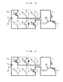
- Figs. 2 to 5 are circuit diagrams for explaining the operation of the inverter 15, in which, for the purpose of preheating a coil of the motor 30, a DC current is supplied so that the motor 30 generates heat through its so-called open-phase operation.
- the voltage applied between the positive and negative input terminals of the inverter 15 is indicated as a virtual power supply E d .
- Transistors Q U , Q V , Q W , Q X , Q Y , and Q Z are respectively a positive switching transistor in U phase, a positive switching transistor in V phase, a positive switching transistor in W phase, a negative switching transistor in the U phase, a negative switching transistor in the V phase, and a negative switching transistor in the W phase.
- the motor 30 further has a Y connection of a U-phase coil L U , a V-phase coil L V , and a W-phase coil L W .
- a pair of the transistors Q U and Q X , a pair of the transistors Q V and Q Y , and a pair of the transistors Q W and Q Z each are connected in series between the positive and negative input terminals of the inverter 15. In each phase, a connection is established between the junction of the pair of transistors and the coil of the motor 30. In each pair, the positive and negative switching transistors are never turned on at the same time. The description in this embodiment is given without reference to a so-called dead time during which both the positive and negative transistors are turned off at the same time.
- both the thick and thin solid lines indicate conducting paths, and the broken line indicates non-conducting paths.
- the thick solid line indicates a path through which current substantially flows, whereas the thin solid line indicates a path through which current does not flow substantially.
- this embodiment illustrates the case where the current substantially flows from the U phase to the V phase, but it goes without saying that those phases may be any other combination of two phases.
- Figs. 2, 3, 4, and 5 illustrate the paths of current flowing responsive to voltage vectors V 0 , V 4 , V 6 , and V 7 , respectively.
- a transition from such one voltage vector to another is achieved by the control circuit 20 that controls voltages applied to the gates of the switching transistors Q U , Q V , Q W , Q X , Q Y , and Q Z .
- the negative switching transistor Q X , Q Y , or Q Z is in the on state; therefore, no voltage is applied to the motor 30.
- the inductance of the U-phase coil L U , the V-phase coil L V , and the W-phase coil L W of the motor 30 maintains the current flow responsive to the other voltage vectors.
- the positive switching transistor Q U in the U phase and the negative switching transistors Q Y and Q Z in the V and W phases are in the on state.
- a voltage E d is applied to the series connection between the U-phase coil L U and the W-phase coil L W .
- the voltage E d is also applied to the series connection between the U-phase coil L U and the V-phase coil L V ; therefore, a transient current can flow from the U-phase coil L U to the V-phase coil L V .
- the positive switching transistors Q U and Q V in the U and V phases and the negative switching transistor Q Z in the W phase are in the on state.
- the voltage E d is applied to the series connection between the U-phase coil L U and the W-phase coil L W .
- the voltage E d is also applied to the series connection between the V-phase coil L V and the W-phase coil L W ; therefore, a transient current can flow from the V-phase coil L V to the W-phase coil L W .
- Fig. 6 is a graph illustrating the voltage applied to the series connection between the U and W phases, i.e., between the U-phase coil L U and the W-phase coil L W , with the passage of time.
- the period t on is the sum of the periods during which the voltage vectors V 4 and V 6 are realized
- the period t off is the sum of the periods during which the voltage vectors V 0 and V 7 are realized.
- the period t on is the period during which the positive switching transistor Q U in the U phase and the negative switching transistor Q Z in the W phase are in the on state and the positive and negative switching transistors Q V and Q Y in the V phase are complementarily in the on state for an equal length of time.
- the period t off is the period during which, in all the phases, either the positive switching transistors Q U , Q V , and Q W are in the on state or the negative switching transistors Q X , Q Y , and Q Z are in the on state.
- T t on + t off .
- power consumption that would be desirable for preheating is predetermined as W ref .
- the detected values of voltage Vm and current Im for the receiving voltage of 200 V are previously stored in the control circuit 20 as a calibrated voltage V ref and a calibrated current I ref , respectively.
- D W ref /( V ref ⁇ I ref ) since it is assumed that the motor 30 receives a voltage of ( V ref ⁇ D ) on average and the current I ref continuously flows throughout all the periods.
- the value of the duty D at this time is also stored as a calibrated duty D 0 .
- the duty D is varied while measuring preheating power consumed by the motor 30, whereby the duty D and the detected value of current Im at the time of the preheating power W ref is defined as the calibrated duty D 0 and the calibrated current I ref .
- the duty D is controlled to be equal to D 0 ⁇ ( V ref ⁇ I ref )/( Vm ⁇ Im).
- the detected values of voltage Vm and current Im are given into of the control circuit 20 via the analog input ports AN0 and AN1 respectively, and the calibrated duty D 0 , the calibrated current I ref , and the calibrated voltage V ref are stored in the control circuit 20. Therefore, if the control circuit 20 controls the periods during which the voltage vectors V 0 , V 4 , V 6 , and V 7 are realized, the duty D can be varied according to the above equation.
- Fig. 7 is a circuit diagram illustrating the compressor motor 30 and its driving circuits in the air conditioner, to which a control method according to a second embodiment of the present invention is applied.
- This embodiment differs from the first embodiment in that the motor 31 comprises a temperature sensing element 31, from which the control circuit 20 receives data.
- the DC resistance R of the coil has temperature dependence that it increases with temperature.
- the detected value of voltage Vm is constant
- the detected value of current Im decreases with increasing temperature
- the duty D is also constant
- preheating power decreases as well. Compensation for preheating can be made even with such temperature variations in the impedance of the motor 30.
- the temperature of the motor 30 is measured by the temperature sensing element 31 and the data obtained is transmitted to the control circuit 20.
- control can be exercised to cancel the temperature dependence by increasing the value of the duty, for example, with increasing temperature obtained from the temperature sensing element 31.
- the reason for increasing the value of the duty is to increase an average value of the voltage applied to the motor and thereby to increase preheating power. That is, preheating power can be set to a desired value irrespective of the temperature of the motor 30.
- This technique is also applicable to the case where alternating current is applied to the motor 30 for heat generation.
Landscapes
- Engineering & Computer Science (AREA)
- Chemical & Material Sciences (AREA)
- Combustion & Propulsion (AREA)
- Mechanical Engineering (AREA)
- General Engineering & Computer Science (AREA)
- Power Engineering (AREA)
- Control Of Ac Motors In General (AREA)
- Inverter Devices (AREA)
- Control Of Electric Motors In General (AREA)
- Control Of Motors That Do Not Use Commutators (AREA)
Abstract
Description
Claims (16)
- A method of controlling preheating power, said method controlling preheating of a coil (LU, LW) of a polyphase motor (30), wherein
said polyphase motor is operated open-phase to generate heat. - The method of controlling preheating power according to claim 1, wherein
said polyphase motor is driven by an inverter (15),
said inverter applying current to said coil (LU, LW) for said preheating of said polyphase motor,
said current being applied with a predetermined period (T) from said inverter to said polyphase motor, on a condition that said polyphase motor should not be rotated, and
as a DC voltage (Vm) applied to said inverter increases, a duty (D) which is the ratio between time during which the voltage is applied to said coil and said period, is set to a smaller value. - The method of controlling preheating power according to claim 2, wherein
in said preheating of said polyphase motor, said current produces no revolving field for said polyphase motor. - The method of controlling preheating power according to either one of claims 1 through 3, wherein
said polyphase motor is a compressor motor in an air conditioner. - The method of controlling preheating power according to claim 2, wherein
said polyphase motor is a three-phase motor,
said inverter is a three-phase inverter, each phase having a pair of positive and negative switching elements (QU, QV, QW, QX, QY, QZ), and
said period includes:a first period (ton) during which said positive switching element (QU) in a first phase (U) is in the on state, said negative switching element (QZ) in a second phase (W) is in the on state, and said positive and negative switching elements (QV; QY) in a third phase (V) are complementarily in the on state for an equal length of time; anda second period (toff) during which, in all of said first, second, and third phases, either said positive switching elements (QU, QV, QW) are in the on state or said negative switching elements (QX, QY, QZ) are in the on state. - The method of controlling preheating power according to either one of claims 2 and 5, wherein
said duty is set to a value obtained by dividing a product of a known calibrated voltage (Vref), a known calibrated current (Iref), and a known calibrated duty (D0) by a product of a current (Im) and a voltage (Vm) applied to said motor. - The method of controlling preheating power according to claim 2, wherein
said duty is set to a larger value as a temperature of said polyphase motor increases. - The method of controlling preheating power according to claim 2, wherein
said preheating is performed on refrigeration oil in a compressor. - A preheating system comprising:a polyphase motor (30) having coils (LU, LW); andan operation control unit for operating said polyphase motor open-phase to generate heat.
- The preheating system according to claim 9, wherein
said operation control unit includes an inverter (15),
said inverter applying current to said polyphase motor with a predetermined period (T), on a condition that said polyphase motor should not be rotated, and
as a DC voltage (Vm) applied to said inverter increases, a duty (D) which is the ratio between time during which the voltage is applied to said coil and said period, is set to a smaller value. - The preheating system according to claim 10, wherein
in said preheating of said polyphase motor, said current produces no revolving field for said polyphase motor. - The preheating system according to either one of claims 9 through 11, wherein
said polyphase motor is a compressor motor in an air conditioner. - The preheating system according to claim 10, wherein
said polyphase motor is a three-phase motor,
said inverter is a three-phase inverter, each phase having a pair of positive and negative switching elements (QU, QV, QW, QX, QY, QZ), and
said period includes:a first period (ton) during which said positive switching element (QU) in a first phase (U) is in the on state, said negative switching element (QZ) in a second phase (W) is in the on state, and said positive and negative switching elements (QV; QY) in a third phase (V) are complementarily in the on state for an equal length of time; anda second period (toff) during which, in all of said first, second, and third phases, either said positive switching elements (QU, QV, QW) are in the on state or said negative switching elements (QX, QY, QZ) are in the on state. - The preheating system according to either one of claims 10 and 13,
wherein
said duty is set to a value obtained by dividing a product of a known calibrated voltage (Vref), a known calibrated current (Iref), and a known duty (D0) by a product of a current (Im) and a voltage (Vm) applied to said motor. - The preheating system according to claim 10, wherein
said duty is set to a larger value as a temperature of said polyphase motor increases. - The preheating system according to claim 10, wherein
said preheating is performed on refrigeration oil in a compressor.
Applications Claiming Priority (3)
| Application Number | Priority Date | Filing Date | Title |
|---|---|---|---|
| JP2000093442A JP3757745B2 (en) | 2000-03-30 | 2000-03-30 | Preheating power control method and preheating generation mechanism |
| JP2000093442 | 2000-03-30 | ||
| PCT/JP2001/002430 WO2001075378A1 (en) | 2000-03-30 | 2001-03-26 | Method of controlling preheating power and mechanism for providing preheating |
Publications (2)
| Publication Number | Publication Date |
|---|---|
| EP1271071A1 true EP1271071A1 (en) | 2003-01-02 |
| EP1271071A4 EP1271071A4 (en) | 2010-03-17 |
Family
ID=18608626
Family Applications (1)
| Application Number | Title | Priority Date | Filing Date |
|---|---|---|---|
| EP01915797A Ceased EP1271071A4 (en) | 2000-03-30 | 2001-03-26 | METHOD FOR CONTROLLING PREHEATING POWER AND PREHEATING MECHANISM |
Country Status (6)
| Country | Link |
|---|---|
| US (1) | US6617819B2 (en) |
| EP (1) | EP1271071A4 (en) |
| JP (1) | JP3757745B2 (en) |
| CN (1) | CN1171115C (en) |
| AU (1) | AU758162C (en) |
| WO (1) | WO2001075378A1 (en) |
Cited By (9)
| Publication number | Priority date | Publication date | Assignee | Title |
|---|---|---|---|---|
| WO2007086648A2 (en) | 2006-01-24 | 2007-08-02 | Lg Electronics Inc. | Air conditioner and control method thereof |
| EP1990591A1 (en) * | 2007-05-08 | 2008-11-12 | Sorgenia S.P.A. | Independent and universal device for controlling the speed of motor-driven compressors of household refrigerating apparatuses and control method thereof |
| WO2010012518A1 (en) * | 2008-07-30 | 2010-02-04 | Siemens Aktiengesellschaft | Drive system comprising the functionality "standstill" |
| EP2214069A1 (en) * | 2009-01-30 | 2010-08-04 | Honeywell International Inc. | HVAC actuator with internal heating |
| EP2112063A3 (en) * | 2008-04-23 | 2013-01-09 | Honeywell International Inc. | Active pilot inceptor with self warm-up |
| CN103154636A (en) * | 2010-08-30 | 2013-06-12 | 三菱电机株式会社 | Heat pump device, heat pump system and three-phase inverter control method |
| EP3136591A3 (en) * | 2015-08-31 | 2017-03-15 | Lg Electronics Inc. | Motor driving apparatus and home appliance including the same |
| EP2515049A4 (en) * | 2009-12-17 | 2018-01-03 | Mitsubishi Electric Corporation | Air conditioner |
| EP4604387A4 (en) * | 2022-10-17 | 2026-01-14 | Gd Midea Air Conditioning Equipment Co Ltd | METHOD AND SYSTEM FOR HEATING AN ELECTRIC MOTOR AS WELL AS STORAGE MEDIUM AND AIR CONDITIONING SYSTEM |
Families Citing this family (33)
| Publication number | Priority date | Publication date | Assignee | Title |
|---|---|---|---|---|
| JP2005218275A (en) * | 2004-02-02 | 2005-08-11 | Daikin Ind Ltd | Motor coil temperature detection device |
| JP2006025565A (en) * | 2004-07-09 | 2006-01-26 | Matsushita Electric Ind Co Ltd | Inverter circuit and compressor |
| KR101253232B1 (en) * | 2005-10-18 | 2013-04-16 | 삼성전자주식회사 | Device For Preheating Compressor And Method Thereof |
| JP2007326450A (en) * | 2006-06-07 | 2007-12-20 | Mazda Motor Corp | Hybrid car |
| JP2007326449A (en) * | 2006-06-07 | 2007-12-20 | Mazda Motor Corp | Hybrid car |
| JP2008231987A (en) * | 2007-03-19 | 2008-10-02 | Mitsubishi Heavy Ind Ltd | Electric compressor |
| US7825621B2 (en) * | 2007-08-28 | 2010-11-02 | Rockwell Automation Technologies, Inc. | Junction temperature reduction for three phase inverters modules |
| US7717048B2 (en) | 2007-10-09 | 2010-05-18 | Deere & Company | Agricultural seeding system |
| JP5560552B2 (en) * | 2008-10-29 | 2014-07-30 | ダイキン工業株式会社 | Inverter device and air conditioner using the same |
| US8734125B2 (en) * | 2009-09-24 | 2014-05-27 | Emerson Climate Technologies, Inc. | Crankcase heater systems and methods for variable speed compressors |
| EP2531328B1 (en) * | 2010-02-05 | 2015-04-08 | Abb Ag | Method for heating a robot in cold environments |
| JP5901765B2 (en) * | 2012-06-29 | 2016-04-13 | 三菱電機株式会社 | Heat pump device, air conditioner and refrigerator |
| GB2503670B (en) * | 2012-07-03 | 2014-12-10 | Dyson Technology Ltd | Method of preheating a brushless motor |
| US9181939B2 (en) | 2012-11-16 | 2015-11-10 | Emerson Climate Technologies, Inc. | Compressor crankcase heating control systems and methods |
| US9353738B2 (en) | 2013-09-19 | 2016-05-31 | Emerson Climate Technologies, Inc. | Compressor crankcase heating control systems and methods |
| US9236828B1 (en) | 2014-07-03 | 2016-01-12 | Rockwell Automation Technologies, Inc. | Methods and power conversion system control apparatus to control IGBT junction temperature at low speed |
| US9318976B1 (en) | 2014-10-30 | 2016-04-19 | Rockwell Automation Technologies, Inc. | Adjustable PWM method to increase low speed starting torque and inverter voltage measurement accuracy |
| US10128788B2 (en) | 2016-01-28 | 2018-11-13 | Trane International Inc. | Increasing component life in a variable speed drive with stator heating |
| CN107014123B (en) * | 2016-01-28 | 2019-08-06 | 珠海格力电器股份有限公司 | Preheating control method, device and system for compressor |
| KR101759906B1 (en) * | 2016-03-14 | 2017-07-31 | 엘지전자 주식회사 | Power converting apparatus and air conditioner including the same |
| CN110463027B (en) * | 2017-03-28 | 2020-11-20 | 大金工业株式会社 | Pulse Width Modulation Method |
| JP2019022421A (en) * | 2017-07-21 | 2019-02-07 | 東芝テック株式会社 | Stepping motor drive device and printer device |
| DE102017118342A1 (en) * | 2017-08-11 | 2019-02-14 | Dr. Ing. H.C. F. Porsche Aktiengesellschaft | Control for a three-phase motor |
| DE102017222684B4 (en) * | 2017-12-14 | 2025-03-27 | Bayerische Motoren Werke Aktiengesellschaft | Method for controlling heat loss in an electric drive motor of a motor vehicle, electric drive unit for a motor vehicle and motor vehicle |
| KR102267355B1 (en) * | 2018-12-28 | 2021-06-18 | 엘지전자 주식회사 | Air conditioner and method thereof |
| CN110138311B (en) * | 2019-06-18 | 2020-06-30 | 宁波奥克斯电气股份有限公司 | Control method and circuit for constant-power preheating of compressor and air conditioner |
| US10784797B1 (en) | 2019-06-19 | 2020-09-22 | Rockwell Automation Technologies, Inc. | Bootstrap charging by PWM control |
| JP7112037B2 (en) * | 2019-06-24 | 2022-08-03 | 三菱電機株式会社 | Air conditioners and air conditioning systems |
| US11336206B2 (en) | 2020-09-23 | 2022-05-17 | Rockwell Automation Technoligies, Inc. | Switching frequency and PWM control to extend power converter lifetime |
| CN112728725B (en) * | 2021-01-22 | 2022-02-11 | 珠海格力节能环保制冷技术研究中心有限公司 | A compressor control device, method and air conditioner |
| CN114623567B (en) * | 2022-03-15 | 2023-10-17 | 青岛海信日立空调系统有限公司 | Air conditioner |
| CN119404425A (en) * | 2022-06-27 | 2025-02-07 | 株式会社电装 | Inverter control device, program |
| CN117938032A (en) | 2022-10-14 | 2024-04-26 | 台达电子工业股份有限公司 | Power control system for preheating motor and power control method thereof |
Family Cites Families (18)
| Publication number | Priority date | Publication date | Assignee | Title |
|---|---|---|---|---|
| US4135122A (en) * | 1977-05-25 | 1979-01-16 | Weyerhaeuser Company | Method and apparatus for heating electrical motors and like devices |
| JPS5649693A (en) * | 1979-09-28 | 1981-05-06 | Hitachi Ltd | Frequency converter |
| JPS6152560A (en) * | 1984-08-22 | 1986-03-15 | 株式会社日立製作所 | Air conditioner |
| AT400273B (en) * | 1986-05-27 | 1995-11-27 | Austria Antriebstech | THREE-PHASE DRIVE WITH FREQUENCY INVERTER CONTROL |
| JP2804796B2 (en) * | 1989-09-01 | 1998-09-30 | 株式会社日立製作所 | Motor control device |
| US5519301A (en) * | 1992-02-26 | 1996-05-21 | Matsushita Electric Industrial Co., Ltd. | Controlling/driving apparatus for an electrically-driven compressor in a car |
| JPH05288411A (en) | 1992-04-07 | 1993-11-02 | Daikin Ind Ltd | Preheat control device for compressor |
| US5450306A (en) * | 1992-12-07 | 1995-09-12 | Square D Company | Closed loop pulse width modulator inverter with volt-seconds feedback control |
| JPH07167504A (en) * | 1993-12-15 | 1995-07-04 | Matsushita Electric Ind Co Ltd | Preheating control method for three-phase electric compressor |
| DE4408325C2 (en) * | 1994-03-11 | 1996-03-07 | Siemens Ag | Method for controlling an inverter of an inverter and arrangement for carrying out the method |
| JPH08114346A (en) | 1994-10-18 | 1996-05-07 | Daikin Ind Ltd | Air conditioner |
| JP3039328B2 (en) * | 1995-07-19 | 2000-05-08 | ダイキン工業株式会社 | Air conditioner |
| JP2980025B2 (en) | 1996-03-29 | 1999-11-22 | ダイキン工業株式会社 | Motor overcurrent protection device |
| JPH09271197A (en) | 1996-03-29 | 1997-10-14 | Daikin Ind Ltd | Motor control device |
| DE19617105C2 (en) * | 1996-04-19 | 1998-07-02 | Mannesmann Ag | Device for recording the current load on funds, especially hoists |
| JPH10141739A (en) | 1996-11-06 | 1998-05-29 | Matsushita Refrig Co Ltd | Air conditioner |
| US5896021A (en) * | 1997-02-06 | 1999-04-20 | General Electric Company | Removal of moisture from induction motors |
| JPH11159467A (en) | 1997-11-28 | 1999-06-15 | Zexel:Kk | Energization control method in motor preheating device and motor preheating device |
-
2000
- 2000-03-30 JP JP2000093442A patent/JP3757745B2/en not_active Expired - Fee Related
-
2001
- 2001-03-26 WO PCT/JP2001/002430 patent/WO2001075378A1/en not_active Ceased
- 2001-03-26 AU AU42788/01A patent/AU758162C/en not_active Ceased
- 2001-03-26 EP EP01915797A patent/EP1271071A4/en not_active Ceased
- 2001-03-26 US US09/979,661 patent/US6617819B2/en not_active Expired - Fee Related
- 2001-03-26 CN CNB018007473A patent/CN1171115C/en not_active Expired - Fee Related
Cited By (16)
| Publication number | Priority date | Publication date | Assignee | Title |
|---|---|---|---|---|
| WO2007086648A3 (en) * | 2006-01-24 | 2009-06-11 | Lg Electronics Inc | Air conditioner and control method thereof |
| WO2007086648A2 (en) | 2006-01-24 | 2007-08-02 | Lg Electronics Inc. | Air conditioner and control method thereof |
| EP1977170A4 (en) * | 2006-01-24 | 2013-12-25 | Lg Electronics Inc | Air conditioner and control method thereof |
| EP1990591A1 (en) * | 2007-05-08 | 2008-11-12 | Sorgenia S.P.A. | Independent and universal device for controlling the speed of motor-driven compressors of household refrigerating apparatuses and control method thereof |
| EP2112063A3 (en) * | 2008-04-23 | 2013-01-09 | Honeywell International Inc. | Active pilot inceptor with self warm-up |
| WO2010012518A1 (en) * | 2008-07-30 | 2010-02-04 | Siemens Aktiengesellschaft | Drive system comprising the functionality "standstill" |
| EP2214069A1 (en) * | 2009-01-30 | 2010-08-04 | Honeywell International Inc. | HVAC actuator with internal heating |
| US8084980B2 (en) | 2009-01-30 | 2011-12-27 | Honeywell International Inc. | HVAC actuator with internal heating |
| EP2515049A4 (en) * | 2009-12-17 | 2018-01-03 | Mitsubishi Electric Corporation | Air conditioner |
| CN103154636A (en) * | 2010-08-30 | 2013-06-12 | 三菱电机株式会社 | Heat pump device, heat pump system and three-phase inverter control method |
| EP2613106A4 (en) * | 2010-08-30 | 2014-05-07 | Mitsubishi Electric Corp | HEAT PUMP DEVICE, HEAT PUMP SYSTEM, AND METHOD FOR CONTROLLING A THREE-PHASE INVERTER |
| AU2010360053B2 (en) * | 2010-08-30 | 2014-08-28 | Mitsubishi Electric Corporation | Heat pump device, heat pump system and three-phase inverter control method |
| CN103154636B (en) * | 2010-08-30 | 2015-08-05 | 三菱电机株式会社 | The control method of heat pump assembly, heat pump and three-phase inverter |
| EP3136591A3 (en) * | 2015-08-31 | 2017-03-15 | Lg Electronics Inc. | Motor driving apparatus and home appliance including the same |
| US10243499B2 (en) | 2015-08-31 | 2019-03-26 | Lg Electronics Inc. | Motor driving apparatus and home appliance including the same |
| EP4604387A4 (en) * | 2022-10-17 | 2026-01-14 | Gd Midea Air Conditioning Equipment Co Ltd | METHOD AND SYSTEM FOR HEATING AN ELECTRIC MOTOR AS WELL AS STORAGE MEDIUM AND AIR CONDITIONING SYSTEM |
Also Published As
| Publication number | Publication date |
|---|---|
| CN1366598A (en) | 2002-08-28 |
| US6617819B2 (en) | 2003-09-09 |
| AU758162B2 (en) | 2003-03-20 |
| JP2001286183A (en) | 2001-10-12 |
| CN1171115C (en) | 2004-10-13 |
| WO2001075378A1 (en) | 2001-10-11 |
| US20030098298A1 (en) | 2003-05-29 |
| EP1271071A4 (en) | 2010-03-17 |
| AU4278801A (en) | 2001-10-15 |
| JP3757745B2 (en) | 2006-03-22 |
| AU758162C (en) | 2003-10-16 |
Similar Documents
| Publication | Publication Date | Title |
|---|---|---|
| US6617819B2 (en) | Method of controlling preheating power and mechanism for providing preheating | |
| US7265954B2 (en) | Method for estimating DC motor coil temperature, DC motor control method and their devices | |
| US4672288A (en) | Torque controller for an AC motor drive and AC motor drive embodying the same | |
| JP2008029193A (en) | Method of adjusting parameters of synchronous motor, and variable speed drive using such a method | |
| US7235947B2 (en) | Synchronous motor control method and synchronous motor control system | |
| CN101295937A (en) | Inverter device and semiconductor device used for inverter device | |
| KR20050077718A (en) | Motor control apparatus | |
| JP2008245501A (en) | Compressor preheating control apparatus and method | |
| US6894450B2 (en) | Circuit configuration for permanent magnet synchronous motor control | |
| US20020021105A1 (en) | Sensorless vector control apparatus and method thereof | |
| JP2023023452A (en) | Motor control device and air conditioner | |
| KR102552538B1 (en) | Apparatus and method for driving a BLDC motor using compensation of voltage | |
| CN100448160C (en) | Operation control device for motor | |
| US7026785B1 (en) | Motor controller | |
| CN110620459B (en) | Drive circuit for operating BLDC motor | |
| CA2327582A1 (en) | Method and apparatus for indirectly measuring induction motor slip to establish speed control | |
| JP2018182975A (en) | Compressor motor drive | |
| AU2018300408B2 (en) | Motor driving apparatus | |
| JPH09191699A (en) | Control method of induction motor | |
| JPH0388980A (en) | Motor heating device | |
| WO2003084047A1 (en) | Controller for a brushless dc motor | |
| CN109915403B (en) | Method for controlling voltage applied to electric fan | |
| KR960012918B1 (en) | Frequency inverter | |
| US20220278634A1 (en) | Method for controlling bus current of brushless dc electric motor, and controller | |
| JP3978694B2 (en) | Electric motor control device |
Legal Events
| Date | Code | Title | Description |
|---|---|---|---|
| PUAI | Public reference made under article 153(3) epc to a published international application that has entered the european phase |
Free format text: ORIGINAL CODE: 0009012 |
|
| 17P | Request for examination filed |
Effective date: 20011228 |
|
| AK | Designated contracting states |
Kind code of ref document: A1 Designated state(s): AT BE CH CY DE DK ES FI FR GB GR IE IT LI LU MC NL PT SE TR |
|
| RBV | Designated contracting states (corrected) |
Designated state(s): BE DE ES FR GB IT |
|
| A4 | Supplementary search report drawn up and despatched |
Effective date: 20100211 |
|
| 17Q | First examination report despatched |
Effective date: 20100309 |
|
| REG | Reference to a national code |
Ref country code: DE Ref legal event code: R003 |
|
| STAA | Information on the status of an ep patent application or granted ep patent |
Free format text: STATUS: THE APPLICATION HAS BEEN REFUSED |
|
| 18R | Application refused |
Effective date: 20141207 |