EP1270999A1 - Toroidal type stepless speed changer slide rotation body and method of evaluating the same - Google Patents
Toroidal type stepless speed changer slide rotation body and method of evaluating the same Download PDFInfo
- Publication number
- EP1270999A1 EP1270999A1 EP02715782A EP02715782A EP1270999A1 EP 1270999 A1 EP1270999 A1 EP 1270999A1 EP 02715782 A EP02715782 A EP 02715782A EP 02715782 A EP02715782 A EP 02715782A EP 1270999 A1 EP1270999 A1 EP 1270999A1
- Authority
- EP
- European Patent Office
- Prior art keywords
- disk
- depth
- defect
- rolling
- ultrasonic
- Prior art date
- Legal status (The legal status is an assumption and is not a legal conclusion. Google has not performed a legal analysis and makes no representation as to the accuracy of the status listed.)
- Withdrawn
Links
Images





Classifications
-
- F—MECHANICAL ENGINEERING; LIGHTING; HEATING; WEAPONS; BLASTING
- F16—ENGINEERING ELEMENTS AND UNITS; GENERAL MEASURES FOR PRODUCING AND MAINTAINING EFFECTIVE FUNCTIONING OF MACHINES OR INSTALLATIONS; THERMAL INSULATION IN GENERAL
- F16H—GEARING
- F16H15/00—Gearings for conveying rotary motion with variable gear ratio, or for reversing rotary motion, by friction between rotary members
- F16H15/02—Gearings for conveying rotary motion with variable gear ratio, or for reversing rotary motion, by friction between rotary members without members having orbital motion
- F16H15/04—Gearings providing a continuous range of gear ratios
- F16H15/06—Gearings providing a continuous range of gear ratios in which a member A of uniform effective diameter mounted on a shaft may co-operate with different parts of a member B
- F16H15/32—Gearings providing a continuous range of gear ratios in which a member A of uniform effective diameter mounted on a shaft may co-operate with different parts of a member B in which the member B has a curved friction surface formed as a surface of a body of revolution generated by a curve which is neither a circular arc centered on its axis of revolution nor a straight line
- F16H15/36—Gearings providing a continuous range of gear ratios in which a member A of uniform effective diameter mounted on a shaft may co-operate with different parts of a member B in which the member B has a curved friction surface formed as a surface of a body of revolution generated by a curve which is neither a circular arc centered on its axis of revolution nor a straight line with concave friction surface, e.g. a hollow toroid surface
- F16H15/38—Gearings providing a continuous range of gear ratios in which a member A of uniform effective diameter mounted on a shaft may co-operate with different parts of a member B in which the member B has a curved friction surface formed as a surface of a body of revolution generated by a curve which is neither a circular arc centered on its axis of revolution nor a straight line with concave friction surface, e.g. a hollow toroid surface with two members B having hollow toroid surfaces opposite to each other, the member or members A being adjustably mounted between the surfaces
-
- G—PHYSICS
- G01—MEASURING; TESTING
- G01N—INVESTIGATING OR ANALYSING MATERIALS BY DETERMINING THEIR CHEMICAL OR PHYSICAL PROPERTIES
- G01N2291/00—Indexing codes associated with group G01N29/00
- G01N2291/04—Wave modes and trajectories
- G01N2291/044—Internal reflections (echoes), e.g. on walls or defects
Definitions
- the present invention relates to sliding rotation members for highly reliable continuously variable transmission (CVT) for use in a toroidal CVT, such as a disk and power roller bearing, and an evaluation method of the members.
- CVT continuously variable transmission
- Prior Document 1 Jpn. Pat. Appln. KOKAI Publication No. 2001-032900 (hereinafter referred to as Prior Document 1), there are disclosed chemical components of alloy steels for use in the input/output disk and power roller bearing, and a carbon amount, nitrogen amount, surface hardness, and the like of a function surface are limited, and preferable alloy components, heat treatment quality, and the like for enhancing the durability.
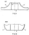
- Prior Document 2 Jpn. Pat. Appln. KOKAI Publication No. 2001-026840 (hereinafter referred to as Prior Document 2), it is disclosed'that a high-cleanliness steel is used in order to prevent breakage and flaking from being generated starting at a large nonmetal inclusion in a steel in a short time. Furthermore, a method of performing an ultrasonic flaw detection/inspection is used to guarantee that the large nonmetal inclusions do not exist in a traction surface 62 and surface layer portion of the input/output disk shown in FIG. 9, and a traction surface 67 and surface layer portion of an inner ring of the power roller bearing shown in FIG. 10. For example, it is guaranteed that the nonmetal inclusion having a maximum size of 0.1 mm or more does not exist within 0.5 mm from the surface in a disclosed member for CVT.
- Prior Document 3 Jpn. Pat. Appln. KOKAI Publication No. 11-193855
- the ultrasonic inspection comprises: transmitting an ultrasonic wave to the inside of a rolled steel material from an outer peripheral surface thereof in water or on a base to detect a flaw.
- a normal wave method described in "page 31, No. 6, Vol. 46, Tokushuko, Tokushuko Club Association” (hereinafter referred to as Prior Document 4), and the like are known.
- the toroidal continuously variable transmission (CVT) disk and power roller bearing member having large defects inside (particularly in the vicinities of surfaces) are sometimes broken in a relatively short time, when repeatedly undergoing bend stresses.
- a rolling member of the large CVT repeatedly undergoes a high bend stress, and therefore tends to flaking or crack starting at a position deeper than a maximum stress generated position in which a conventional general-purpose rolling bearing has heretofore undergone the stress.
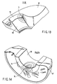
- a large repeated bend stress is added to portions (traction surface 62 and surface layer portion) shown by diagonal lines in FIG. 11, and a high tensile stress is generated.
- the large repeated bend stress is added to portions (traction surface 67, inner peripheral surface 68, rolling surface 69, and surface layer portion) shown by the diagonal lines in FIG. 12, and the high tensile stress is generated. Therefore, the flaking or cracks are easily generated starting at these surfaces 62, 67, 68, 69 and surface layer portions.
- Prior Document 1 it is proposed that the alloy components are optimized and heat treatment quality is specified in order to prevent the generation of the flaking or cracks.
- the traction surfaces 62 and surface layer portions of the input/output disks 31, 32 shown in FIG. 11 are strengthened, and the traction surfaces 67, inner peripheral surfaces 68, rolling surfaces 69, and surface layer portions of power roller inner rings 36a, 37a shown in FIG. 12 are strengthened, so that the entire strength is enhanced.
- Prior Document 2 it is proposed that among the traction surfaces 62, inner peripheral surfaces 63, and surface layer portions of the input/output disks 31, 32 shown in FIG. 11, and the traction surfaces 67, inner peripheral surfaces 68, and rolling surfaces 69 of the power roller inner rings 36a, 37a shown in FIG. 12, particularly the large inclusions of the surface layer portions corresponding to the traction surfaces 62, 67 are detected and guaranteed in order to prevent the breakage or the flaking in the short time.
- a future demand for the CVT lies not only in long life and breakage prevention of the disk and power roller but also in eradication of accidental generation of a short-life bearing. This is a demand for a highly reliable member for the CVT which has no possibility of generation of short-life components even under conditions further stricter than before, with future elongation of guarantee period of a car.
- the present invention has been developed to solve the above-described problems, and an object thereof is to provide a long-life sliding rotation member for CVT in which flaking is not easily generated in a sliding surface, and an evaluation method of a highly reliable sliding rotation member for CVT in which it is possible to detect all defects (particularly, nonmetal inclusions) existing particularly in a surface layer portion of an inner-diameter end in which a stress rises during operation of a CVT constituting member with a high precision.
- a toroidal CVT can bear a larger input torque than other CVTs (e.g., a belt CVT) can.
- the toroidal CVT receives a larger input torque.
- the toroidal CVT is of a type such that a large load can be received as compared with the belt CVT, and therefore a higher load and surface pressure are applied to a disk and power roller. In the future it is expected that a portion undergoing a repeated bend fatigue is positioned more deeply in the toroidal CVT.
- Prior Document 2 the present inventors have proposed that the nonmetal inclusion existing within 0.5 mm right under the traction surface and having a maximum diameter of 0.1 mm or more is limited and this can prevent the member from breaking. That is, as a result of intensive researches, the present inventors have found that the nonmetal inclusion (defect) existing within 0.5 mm from the traction surface and having a maximum diameter of 0.1 mm or more is a start point of bend fatigue destruction of a CVT component, and have proposed concrete solution means in Prior Document 2 based on the finding.
- breakage the bend fatigue destruction
- the toroidal CVT component even in a position of the nonmetal inclusion deeper than the position described in Prior Document 2 described above. That is, as a result of the research under a stress condition stricter than a conventional condition, the present inventors have found that the breakage is sometimes generated even in a position deeper than the depth disclosed in Prior Document 2 and that the breakage is sometimes generated even in a defect smaller than the defect with the size disclosed in Document 2.
- the present inventors have intensively researched a relation between the input torque and breakage and the size of the nonmetal inclusion.
- the defect having a square root length of 0.1 mm or more is prevented from existing in a region within twice a depth of a position (Z 0 ) of maximum shear stress undergone by the toroidal CVT component, and this can prevent the toroidal CVT component from breaking.
- the sliding surface undergoes rolling fatigue between the disk and power roller.
- the large nonmetal inclusion exists right under the sliding surface, there is a problem that the flaking is generated with the short life.
- the toroidal CVT component flaking a trouble is generated in the running of a car. Therefore, it is important to lengthen the life against the rolling fatigue and eradicate short-life components.
- the present inventors have found that the elimination of the nonmetal inclusion having a square root length of 0.05 mm or more within twice the depth (Z 0 ) of maximum shear stress undergone by the toroidal CVT component can prevent the component from peeling in a short time.
- the present inventors have noted the ultrasonic inspection as a method of evaluating the nonmetal inclusion existing under the sliding surface of the disk and power roller bearing of the CVT, and have made intensive efforts in the improvement of the inspection method.
- it has been found that it is possible to detect the nonmetal inclusion of 0.1 mm or less existing within 0.5 mm from the surface with application of an angle wave method (surface wave method), and this has been disclosed in Prior Document 2 described above.
- a main object of the invention disclosed in Prior Document 2 is to detect the defect in a relatively shallow position within 0.5 mm from the surface.
- a depth of 2 mm to 3 mm is an object depending on the size of the input torque. Therefore, it is necessary to also detect the defects (including the nonmetal inclusion, macro-streak flaw, and open crack) each having a square root length of 0.05 mm or more or 0.1 mm or more in a position of a depth six times a conventional object depth.
- Prior Document 2 described above discloses a method of detecting the defect in the depth of 0.5 mm under the surface. Furthermore, the present inventors have intensively researched the ultrasonic inspection in which the portion having a depth of 0.5 mm or more under the surface can be inspected with a high precision, and have completed the present invention.
- a toroidal continuously variable transmission comprising: an input disk disposed on an input shaft; an output disk disposed on an output shaft; and a power roller bearing which includes an inner ring, an outer ring and a plurality of rolling members, in which the inner ring is rollingly contacted in the input disk and output disk and which transmits a power of the input' shaft to the output shaft, wherein a maximum shear stress depth obtained on a condition on which the input disk is rolling contacted in the inner ring of the power roller bearing in a maximum deceleration state of the toroidal continuously variable transmission and the power is transmitted is defined as a symbol Zo, a size of a defect obtained in accordance with a shape of the defect detected by a nondestructive inspection method is defined as a square root length, and then at least one of the input disk and the inner ring of the power' roller bearing does not include a defect of 0.05 mm or more in terms of the square root length in a range of a depth from a traction surface
- a sliding rotation member for a toroidal continuously variable transmission which is rotatably supported by a support shaft in the toroidal continuously variable transmission, and slides on another member, wherein a maximum shear stress depth generated at a maximum deceleration time of the toroidal continuously variable transmission is defined as Z 0 , a size of a defect obtained in accordance with a shape of the defect detected by a nondestructive inspection method is defined as a square root length, and then a defect of 0.05 mm or more in terms of the square root length is not included in a range of a depth from the surface of the sliding rotation member which is twice the above-described Z 0 .
- the defect includes a nonmetal inclusion, macro-streak flaw, and opening crack. Since most of the defects detected from CVT components are the nonmetal inclusions, it is essential to prevent large nonmetal inclusions from existing in portions shown by diagonal lines in FIGS. 7, 8. In general, the large nonmetal inclusion has a maximum diameter of 0.05 mm or more, and there are nonmetal inclusions having various shapes. Therefore, the size of the defect is defined by the square root length entirely in the present invention.
- the "square root length” is obtained in the following 1) and 2) in accordance with the shape of the defect.
- the defect existing in the range of the depth from the rolling contact surface (traction surface) twice the maximum shear stress depth Z 0 is an object.
- the defect is detected using a combination of a surface wave method, angle wave method, and normal wave method, acceptance/rejection is judged based on the detected result, and a defect of 0.10 mm or more in terms of the square root length is prevented from being included in the portion of the depth range (claim 1). In this case, it is more preferable on quality assurance to prevent the defect of 0.05 mm or more (particularly the nonmetal inclusion) from being included (claim 2).
- the another member is the inner ring of the power roller bearing, that is, when the sliding rotation member is the input disk or the output disk, as shown in FIG. 7, it is preferable not to include a defect exceeding 0.20 mm in terms of the square root length (particularly the nonmetal inclusion) in a portion in at least a half depth L1 of a diametric length of an end surface on an inner peripheral surface side and in at least one-third depth C/3 of an axial length of the inner peripheral surface from an end surface side (claim 3).
- the another member is an input or output disk, that is, the sliding rotation member is a power roller bearing inner ring.
- the sliding rotation member is a power roller bearing inner ring.
- an evaluation method of a sliding rotation member for a toroidal continuously variable transmission comprising: immersing the sliding rotation member rotatably supported by a support shaft in the toroidal continuously variable transmission and slid on another member during use together with an ultrasonic probe into a transmission medium; allowing an ultrasonic wave to be incident upon the sliding rotation member from the ultrasonic probe via the transmission medium; and evaluating defects existing in the surface and an inner portion of the sliding rotation member based on a waveform of ultrasonic echo reflected from the sliding rotation member, the method comprising:
- the surface (incidence surface) upon which the ultrasonic wave is incident is a traction surface or end surface of the sliding rotation member.
- the traction surface is a surface which undergoes a dynamic repeated stress by a mutual sliding contact with the other members.
- the ultrasonic wave is transmitted into the sliding rotation member from the end surface (claim 5).
- the end surface is positioned between the inner peripheral surface brought into contact with or disposed opposite to the support shaft and the traction surface, and substantially crosses at right angles to the support shaft.
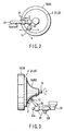
- ultrasonic waves 4 are transmitted into a portion in a half (L1) of the diametric length W of an end surface 70 from an inner peripheral surface 63 side and a depth C/3 which is at least 1/3 of the axial length of the inner peripheral surface 63 from an end surface 70 side, and a surface layer portion right under the end surface 70 and inner peripheral surface 63 is scanned.
- the ultrasonic wave is transmitted into the sliding rotation member from the end surface (claim 6).
- the end surface is in a position defined by the inner peripheral surface brought into contact with or disposed opposite to a pivot shaft 50, pivot shaft, and rolling groove, and substantially crosses at right angles to the pivot shaft.
- the ultrasonic waves 4 are transmitted into a portion in a half (L2) of a diametric length G of an end surface 75 from an inner peripheral surface 68 side and a depth F/2 which is at least a half of the axial length of the inner peripheral surface 68 from an end surface 75 side, and the surface layer portion right under the end surface 75 and inner peripheral surface 68 is scanned.
- an ultrasonic wave with a predetermined frequency in a range of 5 MHz to 30 MHz in the steps (a) and (b). It is further preferable to use an ultrasonic wave with the predetermined frequency in a range of 5 MHz to 15 MHz in the step (a) and to use an ultrasonic wave with the predetermined frequency in a range of 10 MHz to 25 MHz in the step (b).
- the angle wave method or the surface wave method is used in inspecting the depth of 0.5 mm from the surface, and the defect is detected in a frequency range of 5 MHz to 30 MHz, preferably 5 MHz to 15 MHz. Furthermore, the angle wave method or the normal wave method is used in inspecting a depth exceeding 0.5 mm from the surface in which the ultrasonic wave is attenuated inside the material and it is difficult to detect the defect.
- the angle wave method or the normal wave method is used to detect the defect in a frequency range of 5 MHz to 30 MHz, preferably 10 MHz to 25 MHz.
- a method for use in detecting the deep range is generally the normal wave method (immersion method), but a position shallower than 0.5 mm is a region (dead band) which cannot be detected by the surface echo to reflect a sonic wave on the surface, and the defect cannot be detected in the normal wave method.
- the present inventors have found an optimum method in which the ultrasonic wave is transmitted from the specific surface and a CVT member is highly precisely scanned in order to detect the nonmetal inclusion existing in a surface layer region right under the surface.
- a detection limit in ultrasonic inspection is generally a 1/2 wavelength, but according to the method of the present invention, it is possible to detect the defect having a square root length of 0.05 mm in the vicinity of the surface.
- the sonic wave is largely attenuated, and it is difficult to detect the flaw in the target depth. Therefore, a flaw detection frequency is limited to a range of 5 MHz to 30 MHz.
- a frequency of 5 MHz to 15 MHz is preferable in a range of 0.5 mm from the surface, and a frequency of 10 MHz to 25 MHz is preferable in a range of 0.5 mm to twice the maximum shear stress depth Z 0 (practically a depth of 2 to 3 mm).
- a detection intensity having a desired magnitude is maximized.
- the above-described method is suitable for scanning the portion which undergoes a high bend stress other than the traction surface.
- the toroidal continuously variable transmission (CVT) is used in an environment having high load and surface pressure, and therefore undergoes a load much larger than the general-purpose rolling bearing.
- the repeated bend stress is applied to the diagonal-line portion in FIG. 11 (the surfaces 62, 63 and the surface layer portion right under the surfaces), and a high tensile stress is generated.
- the repeated bend stress is applied to the diagonal-line portion in FIG. 12 (the surfaces 67, 68, 69 and the surface layer portion right under the surfaces), and the high tensile stress is generated. Therefore, the input/output disk and power roller bearing inner ring easily flaking and break starting from these portions.
- Prior Document 2 there is disclosed the ultrasonic inspection method which guarantees that large nonmetal inclusions do not exist in the traction surface 62 of the input/output disk and the traction surface 67 and surface layer portion right under the surface of the power roller bearing inner ring.
- the portions shallow from the traction surfaces 62, 67 are objects, and the portions further deeper from the traction surface are not the objects.
- only the surface layer portion right under the traction surface is regarded as the object, and other surface layer portions distant from the traction surface are not the objects.
- a main use of the toroidal CVT is a car, but if a damage (flaking or breakage) is enerated in the input/output disk or the power roller bearing, the other components in the CVT mechanism are crucially damaged and a serious accident is possibly caused. Particularly, when the input/output disk or the power roller bearing inner ring breaks during the running of the car, there is a possibility of development of a major accident. Therefore, it is necessary to guarantee quality so that these components are inhibited from breaking.
- the present inventors have assumed the repeated bend stress applied to the input/output disk and power roller bearing inner ring in an apparatus with the CVT mounted thereon, and have analyzed a stress distribution generated in the respective members by a finite element method (FEM) using computer graphics simulation.
- FEM finite element method
- the present inventors have noted these high-stress generated regions 71, 76, and have intensively researched correlations of size, depth position, and breakage (flaking) of the large nonmetal inclusion included in the surface layer portion.
- the large nonmetal inclusions having a square root length of 0.2 mm or more are prevented from being included in regions shown by diagonal lines of FIGS. 7 and 8 and the breakage (flaking) can thereby be prevented regardless of any size of the disk and power roller bearing inner ring. That is, the high-stress generated regions 71 of the input/output disks 31, 32 correspond to the portion 61 shown by diagonal lines in FIG. 7, and the high-stress generated regions 76 of the power roller bearing inner rings 36a, 37a correspond to the portion 66 shown by diagonal lines in FIG. 8.
- the present inventors have confirmed that the flaking or breakage is not generated during a guaranteed life regardless of the sizes of the input/output disk and power roller bearing, as long as the portions of the regions shown by the diagonal lines in FIGS. 7, 8 have a certain constant cleanliness (substantially have no defect).
- the "surface layer portion” includes not only the portion right under the surface but also the portion in a certain degree of depth from the surface and further the surface.
- the present inventors have obtained the maximum shear stress depth Z 0 from toroidal CVT design conditions in accordance with the following procedure, have used an obtained Z 0 value as a reference to apply various ultrasonic inspections such as the normal wave method, angle wave method, and surface wave method to the input/output disk and power roller bearing inner ring, and have checked the methods.
- Table 3 it has been found that the angle wave method is most suitable for the depth from the surface in a range of once or twice Z 0 and that the surface wave method and normal wave methods are most suitable for the depth from the surface in a range of twice or more times Z 0 .
- This Z 0 of a time at which the input/output disk and power roller bearing inner ring of the toroidal CVT are rotated and brought into contact, and a method of obtaining Z 0 will be described with reference to FIGS. 19 and 20.
- the depth position on which the dynamic maximum shear stress acts is referred to as the "maximum shear stress depth Z 0 ".
- the maximum shear stress depth Z 0 is used in calculating a rolling life of each constituting member, when designing the CVT.
- symbol a denotes a contact ellipse long axis radius
- symbol b denotes a contact ellipse short axis radius
- symbol ⁇ denotes an auxiliary angle
- symbols ⁇ and ⁇ denote constants concerning cost
- symbol P denotes a load
- numeric values are use to obtain the curvature radii ⁇ 11 , ⁇ 12 , ⁇ 21 , ⁇ 22 . Additionally, for the values of the ⁇ 11 , ⁇ 12 , ⁇ 21 , ⁇ 22 , fifth digits after the decimal point are rounded off.
- the Zo value is 0.614 mm
- P max value is 4.05 GPa.
- the present invention attention is focused on the inspection of the portion in which destruction most easily occurs in the toroidal CVT member, and thereby the quality of the CVT member can be guaranteed with high precision.
- the inspection precision of the defect is dramatically enhanced, and therefore a level of quality assurance can be raised.
- the defect included in the CVT member is scanned in a nondestructive manner, the total number of CVT members can be inspected, and it is possible to guarantee the quality with the high reliability.
- the true size and shape of the defect can be grasped based on the echo reflected from the defect. Therefore, the high reliability can be obtained as compared with the conventional method of using a microscope to two-dimensionally observe the defect which appears in a cut surface.
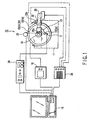
- FIG. 1 is a schematic diagram showing a ultrasonic flaw detection/inspection apparatus.
- a reference numeral 11 in the drawing denotes a water tank in which water as an ultrasonic transmission medium is pooled.
- a CVT disk (or may be a power roller bearing inner ring) as an object 2 and an ultrasonic probe 3 are immersed in water and disposed in the water tank 11.
- a focus type probe including a focus mechanism which has strong directivity and which is not easily influenced by a curvature of the object 2 (31, 32, 36a, 37a).
- the focus type probe has a high S/N ratio.
- the object 2 is disposed on a turntable 15 (16) while a disk surface is directed on the side of the probe 3.
- the axis of the object 2 is the same as the rotation axis of the turntable 15 (16), and both members are synchronously rotated/drive by a servo motor 14.
- a reference numeral 18 denotes a control amplifier for driving the servo motor 14.
- the probe 3 is attached to the tip end of a swing arm 23 via an attachment plate 13.
- the swing arm 23 is supported by an XY table 22 which can move both in a radius direction and axial direction of the object 2 under two-axes control.
- the XY table 22 includes two drivers 22a, 22b controlled by a controller 26. These drivers 22a, 22b allow the probe 3 together with the XY table 22 to move along a sliding surface 2a (62) of the object 2 (31, 32).
- the XY table 22 is movably supported by a linear guide apparatus 20.
- the linear guide apparatus 20 moves the probe 3 for ultrasonic inspection in the axial direction via a servo motor (not shown) controlled by the controller 26 for linear guide.
- a rotary encoder 25 disposed on the outer peripheral surface of the object 2 detects one rotation (360°) of the object 2
- the controller 26 for linear guide controls the servo motor based on an instruction from a control apparatus 19 and moves the probe 3 by a predetermined distance in the axial direction of the object 2. Thereby, the whole section of the object 2 is searched for detecting defects.
- the probe 3 may be moved in parallel on the diameter (passed through a center) of the object 2 in accordance with an angle with an offset of plus/minus several millimeters. Moreover, the probe 3 may be swung on the diameter of the object 2.
- the probe 3 is connected to both input and output portions of an ultrasonic flaw detection apparatus 24.
- the probe 3 transmits an ultrasonic pulse to the outer peripheral surface 2a of the object in accordance with a voltage signal from the ultrasonic flaw detection apparatus 24, receives reflected echo, converts the echo to the voltage signal and sends the signal back to the ultrasonic inspection apparatus 24.
- the ultrasonic inspection apparatus 24 transmits an instruction signal including the voltage signal to the probe 3 for ultrasonic probing based on the instruction from the personal computer 19 as the control apparatus, and sends flaw detection information obtained based on transmitted and received signals back to the control apparatus 19. Thereby, the control apparatus 19 displays a waveform of ultrasonic echo on a CRT screen.
- the probe 3 moves by a predetermined distance on a curve determined beforehand in accordance with the size of the object 2, and scans the sliding surface 2a of the object 2. Thereby, the total surface of the object 2 is scanned for detecting the defects.
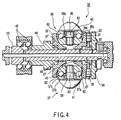
- a toroidal CVT apparatus 30 will next be described with reference to FIG. 4.
- the apparatus has a structure in which an input disk 31 and output disk 32 are disposed opposite to each other on the same shaft in a housing (not shown).
- An input shaft 33 is passed through a axis center portion of the toroidal transmission including the input disk 31 and output disk 32.
- a loading cam 34 is disposed on one end of the input shaft 33. Moreover, the loading cam 34 transmits a power (turning force) of the input shaft 33 to the input disk 31 via a cam roller 35 in the structure.
- the input disk 31 and output disk 32 have substantially the same shape, are symmetrically disposed, and are formed on the traction surface so that the opposite surfaces of the disks cooperate to form a substantially semicircular shape as viewed in a axial section. Moreover, a pair of power roller bearing 36 and power roller bearing 37 for transmitting operation are disposed in contact with the input disk 31 and output disk 32 in toroidal cavities formed by the traction surfaces 62 of the input disk 31 and output disk 32 in the structure.
- the power roller bearing 36 includes an inner ring 36a, outer ring 36b and a plurality of rolling members (steel balls) 36c of the power roller bearing which rolls/runs on the traction surfaces 62 of the input disk 31 and output disk 32.
- the other power roller bearing 37 includes a power roller inner ring 37a, outer ring 37b and a plurality of rolling members (steel balls) 37c which roll/run on the traction surfaces 62 of the input disk 31 and output disk 32.
- the power roller bearing inner rings 36a, 37a also serve as the rolling members of the power roller bearings 36, 37, respectively.
- One power roller bearing inner ring 36a is rotatably attached to a trunnion 40 via a pivot 38, the outer ring 36b and the plurality of rolling members 36c, and supported so that the ring can be tilted/rotated centering on a pivot shaft 50 as a center of the traction surfaces of the input disk 31 and output disk 32.
- the other power roller bearing inner ring 37a is rotatably attached to a trunnion 41 via a pivot 39, the outer ring 37b and the plurality of rolling members 37c, and supported so that the ring can be tilted/rotated centering on the pivot shaft 50 as the center of the traction surfaces of the input disk 31 and output disk 32. Furthermore, a lubricant having a large viscosity friction resistance is supplied to mutual contact surfaces of the input and output disks 31, 32 and power roller bearing inner rings 36a, 37a. The power inputted into the input disk 31 is transmitted to the output disk 32 via a lubricant film and power roller bearing inner rings 36a, 37a in this lubricated state.
- the input disk 31 and output disk 32 are independent of the input shaft 33 via needles 45 (that is, the disks are not directly influenced by the power of the rotation shaft 33).
- An output shaft 44 disposed in parallel with the input shaft 33 and rotatably supported by the housing (not shown) via angular bearings 42 is disposed on the output disk 32.
- the power of the input shaft 33 is transmitted to the loading cam 34 in the toroidal continuously variable transmission 30. Moreover, when the loading cam 34 rotates by the transmitted power, the power by the rotation is transmitted to the input disk 31 via the cam roller 35, and the input disk 31 rotates. Furthermore, the power generated by the rotation of the input disk 31 is transmitted to the output disk 32 via the power roller bearing inner rings 36a, 37a. Additionally, the output disk 32 rotates integrally with the output shaft 44.
- the trunnions 40 and 41 are moved in a pivot shaft 50 direction by a micro distance. That is, by the axial movement of the trunnions 40 and 41, the intersections of the rotation shafts of the power roller bearing inner rings 36a, 37a and the shafts of the input disk 31 and output disk 32 slightly deviate. Then, a balance between rotation peripheral speeds of the power roller bearing inner rings 36a, 37a and input disk 31 is destroyed, and both the power roller bearing inner rings 36a, 37a are tilted/rotated around the pivot shaft 50 by a component force of a rotating/driving force of the input disk 31.
- both the power roller bearing inner rings 36a, 37a are tilted/rolled on curved surfaces of the input disk 31 and output disk 32, a speed ratio changes as a result, and deceleration or acceleration is performed.
- a limit of an angle of incidence of an ultrasonic wave in the present invention will next be described. That is, an angle wave method in which the angle of incidence exceeds 30° will be described.
- the ultrasonic wave On entering the member to be inspected containing iron, steel at an angle of incidence i L , the ultrasonic wave is divided into transverse and longitudinal waves, and an angle of refraction ⁇ L of the longitudinal wave is larger than an angle of refraction ⁇ S of the transverse wave.
- the relation between the angle of incidence and angle of refraction only with respect to the transverse wave is a relation represented by the following equations (7) and (8).
- the probe 3 for ultrasonic inspection serves as both a transmitter and receiver, and a received signal (flaw signal) returns along a reverse path (tracks backwards along the same path as that of transmission).
- a received signal (flaw signal) returns along a reverse path (tracks backwards along the same path as that of transmission).
- An intensity of echo returns to water from iron, steel, but the return signal may be either the transverse wave or the longitudinal wave, and both the transverse and longitudinal waves may return.
- the angle of incidence i L is not less than a certain value
- the angle of refraction in iron, steel is not less than 90°, and the flaw signal only runs on the surface or is reflected by the surface and does not return to the probe 3 for the ultrasonic inspection.
- the limit of the angle of incidence is theoretically about 28° from the above equations (7) and (8) in which ⁇ S : 90° is assumed. However, in actual, the sonic wave is issued with a certain degree of width, and the flaw can sufficiently be detected at 30°.
- a case in which the angle of refraction ⁇ S of the transverse wave is 90° is called a surface wave method.
- the sonic wave is oscillated from a vibrator with a certain degree of width (spread). Therefore, a case in which the angle of incidence i L is in a range of 26° to 30° is defined as the "surface wave method" in the present invention.
- a case in which the angle of incidence is 0° is called a normal wave method.
- the ultrasonic wave oscillated from the focus type probe is incident upon an optical axis with a certain degree of angle.
- a case in which the angle of incidence i L is in a range of 0° to 5° is defined as the "normal wave method” in the present invention. Furthermore, a case in which the angle of incidence i L is in a range of 6 to 25° is defined as an "angle wave method" in the present invention.
- Embodiment 1 A method of detecting the defect in the disk of the toroidal CVT and evaluating the detected defect will next be described as Embodiment 1.
- Table 3 shows results of evaluation as to whether or not the defect with a square root length of 0.05 mm performed can be detected.
- the evaluation was performed, while the angle of incidence of the ultrasonic wave was changed.
- the inspection method comprised: scanning the disk for the flaw by each angle of incidence; and detecting the defect, the position and size of the defect were actually specified from the surface of the disk by run-in grinding, a relation between detection intensity and depth was derived, and the defect was evaluated based on the relation.
- the surface wave method is best for the vicinity of the surface, and the angle wave method is best for a slightly deep region. Therefore, it is necessary to select incidence conditions of the ultrasonic wave in the surface to be inspected in accordance with the depth of the disk to be inspected.
- Embodiment 1 when the perpendicular wave method is combined with the oblique angle or surface wave method, it is possible to detect a large defect having a square root length of 0.05 mm or more existing in the portion having a depth of Z 0 ⁇ 2 (mm) from the surface.
- the traction surface of the CVT disk was subjected to the ultrasonic inspection similarly as Example 1, the disks in which the square root lengths of the detected defects are in ranges of 0.05 mm to 0.07 mm and 0.10 mm to 0.12 mm were taken out, further test pieces were classified by the depth from the sliding surface, and a durability test was performed. Additionally, the depth in which the defect was present was sorted out with the multiple of the maximum shear stress generated position Z 0 in the following durable condition.
- FIG. 5 is a characteristic graph in which the abscissa indicates the position of the defect from the surface, the ordinate indicates the breakage time of the member in the durability test, and a result of check concerning the influence of the size and position of the defect onto a breakage time (life) is shown.
- a characteristic line "A" shows the result of check of the breakage time with respect to the member to be inspected in which the defects each having the square root length in a range of 0.05 to 0.07 mm exist in depth positions once, twice, three times, four times the maximum shear stress depth Z 0 .
- a characteristic line "B" shows the result of check of the breakage time with respect to the member to be inspected in which the defects each having the square root length in a range of 0.10 to 0.13 mm exist in the depth positions once, nearly twice, a little over twice, three times, four times the maximum shear stress depth Z 0 .
- the defect (small defect) having a square root length of 0.05 to 0.07 mm does not influence the breakage life regardless of the depth position.
- the defect (large defect) having a square root length of 0.10 to 0.13 mm is positioned in the depth twice the maximum shear stress depth Z 0 , the breakage life is remarkably short.
- the inspected members No. 1 to No. 3 in which the depth position with the defects existing therein is within Z 0 ⁇ 2 have large defects each having the square root length of 0.10 mm or more. It has been found that the members break in short times such as 40 hours, 90 hours, and 175 hours. On the other hand, even for the inspected members No. 4 and No. 5 having large defects each having the square root length of 0.10 mm or more, when the depth position with the defects existing therein exceeds Z 0 ⁇ 2 and is Z 0 ⁇ 3 or more, the members do not break even exceeding 500 hours. Moreover, even when the depth position with the defects existing therein is within Z 0 ⁇ 2, the inspected members (No. 6 and No. 7) including the defects each having the square root length of 0.05 mm to 0.7 mm do not break even exceeding 500 hours.
- FIG. 6 is a characteristic graph in which the abscissa indicates the position of the defect from the surface, the ordinate indicates a flaking life L10 (time) of the member in an L10 life test, and a result of check concerning the influence of the position of the defect having the square root length of 0.05 to 0.07 mm onto the L10 life is shown.
- a characteristic line C is obtained by plotting and connecting the results of the check of the L10 life with respect to the inspected member in which the defects each having the square root length of 0.05 to 0.07 mm exist in depth positions once, twice, three times, four times the maximum shear stress depth Z 0 .
- the defect having the square root length of 0.05 to 0.07 mm is positioned in the depth within twice the maximum shear stress depth Z 0 , the L10 life remarkably becomes short. This result was obtained. Additionally, it has been confirmed that the defect with the same size is substantially harmless for a fatigue flaking strength with a depth three or more times the maximum shear stress depth Z 0 (the flaking does not occur in 600 hours)
- a method of inspecting a portion in which the stress builds up other than the traction surfaces of the input/output disk and power roller bearing inner ring of the toroidal CVT will next be described as Examples 3, 4 of the present invention with reference to FIGS. 7, 8, 15 to 18 and Tables 4, 5. Additionally, materials dissolved from different material charges were used to manufacture the input/output disks 31, 32 and power roller bearing inner rings 36a, 37a. After completion and before assembly, the angle wave method and normal wave method were used to check whether or not the large nonmetal inclusion having a square root length of 0.20 mm or more exists in the portions shown by diagonal lines in FIGS. 7, 8.
- a steel material of JIS SCM435 was used in the materials of the input disk 31 and power roller bearing inner rings 36a, 37a.
- the steel material was subjected to a carbonitriding treatment so that the total concentration of carbon and nitrogen of the surface was in a range of 0.9 to 1.2%, and subsequently subjected to hardening/tempering, and the surface was finished/processed.
- the hardness of the finished/processed surface was in a range of 720 to 780 in terms of Vickers hardness Hv.
- a surface hardening treatment may be performed as described above. With the similar hardness, for example, JIS SCM420, SCM440, SCR420, and the like may be used.
- a carburization treatment is performed instead of the above-described carbonitriding treatment, the similar result is obtained with respect to a crack life.
- similar materials are also used in output disk 32 and power roller bearing outer rings 36b, 37b.
- a common evaluation method of inspecting the portion in which the stress rises other than the traction surfaces of the input/output disk and power roller bearing inner ring comprised: using the apparatus shown in FIGS. 1 to 3 to subject the portion to the ultrasonic flaw detection.
- the depth of 3 mm (inspection gate) from an end surface 70 was scanned at an angle of incidence of 28° (angle of refraction of 90°).
- the depth of 3 mm (inspection gate) from an end surface 77 was scanned at an angle of incidence of 19° (angle of refraction of 45°).
- the depth of 3 mm or more from the end surface was perpendicularly scanned at the angle of incidence of 0°.
- the probe was operated so as to obtain the above-described angle of incidence, and the size (width and length) and position of the defect were estimated/evaluated from information such as X-Y axis coordinate, R axis angle, height of defect echo, reflected range of echo, and beam exposure distance from the echo in automatic flaw detection.
- Embodiment 3 A method of inspecting a surface layer portion 61 right under the inner peripheral surface/end surface of the disk 31 (32) will be described as Embodiment 3 with reference to FIGS. 15, 16 and Table 4.
- the inspection object portion 61 of the disk is assumed to be in a range of a depth L1 which is a half of the diametric length of the end surface 70 from an inner peripheral surface 63 side (about the half of the end surface 70 (e.g., 6 mm), and a depth C/3 which is at least 1/3 of the axial length of the inner peripheral surface 63 from an end surface 70 side.
- the disk 31 is immersed in water as the ultrasonic wave transmission medium, and the ultrasonic oscillation surface of the probe (not shown) is positioned with respect to the end surface 70 of the disk 31 so that the angle of incidence ⁇ is 28° (the angle of refraction is 90°). It is confirmed that the probe is correctly positioned in a flaw detection start position with the surface wave incident thereupon. Thereafter, the disk 31 is rotated around the shaft at a predetermined rotation speed. Moreover, the ultrasonic wave is oscillated toward the end surface 70 of the disk 31, and the surface wave probe (not shown) is moved in parallel with the radial direction of the disk 31 toward an inner peripheral side from an outer peripheral side. Thereby, the end surface 70 is scanned in a range of width L1 from the inner peripheral surface 63 of the disk 31.
- the ultrasonic oscillation surface of a probe 3a attached to the arm 23 is positioned with respect to the end surface 70 of the disk 31 so as to obtain the angle of incidence ⁇ of 19° (angle of refraction of 45°).
- the disk 31 is rotated around the shaft at the predetermined rotation speed, the ultrasonic wave is oscillated toward the end surface 70 of the disk 31, and the probe 3a is moved in parallel with the radius direction of the disk 31 toward the inner peripheral side from the outer peripheral side.
- ultrasonic waves 4 are incident upon the rotating disk 31 at the angle of incidence of 19° ( ⁇ ) from the end surface 70, and the angle beam probe 3a is moved in parallel with the end surface 70 toward the right from the left of the drawing.
- the parallel movement of the angle beam probe 3a is stopped.
- a first portion 61a is scanned in a range of a depth d1 (e.g., 2 to 3 mm) from the end surface 70 and a depth L1 from the inner peripheral surface 63 (a half of width W of the end surface 70 (e.g., 6 to 8 mm)).
- the angle beam probe 3a is detached from the arm 23, and replaced with a normal beam probe 3b.
- the normal beam probe 3b is positioned with respect to the end surface 70 of the disk 31.
- the disk 31 is rotated around the shaft at the predetermined rotation speed, the ultrasonic wave is oscillated toward the end surface 70 of the disk 31 and the normal beam probe 3b is moved in parallel with the radius direction of the disk 31 toward the inner peripheral side from the outer peripheral side.
- the ultrasonic waves 4 are incident upon the rotating disk 31 at the angle of incidence of 0° from the end surface 70, and the normal beam probe 3b is moved in parallel with the end surface 70 toward the right from the left of the drawing.
- the parallel movement of the normal beam probe 3b is stopped.
- the size and position of the defect were estimated as follows.
- the disk from which some defect echoes could be obtained was cut, the cut surface was observed in detail with a microscope, and thereby a relation (calibration) between the size (width and length) and depth position from the surface of the large nonmetal inclusion and the ultrasonic echo intensity was grasped.
- the calibration and measured defect echo were used to estimate the size and position of the defect which would be inside the member.
- Table 4 shows the position and size of the defect (large nonmetal inclusion) detected beforehand in the input disk used in crack life evaluation. Additionally, since a larger load was applied to the input disk than to the output disk (used in the strict stress condition), the input disk was representatively tested. These test specimens were used to perform a simulation durability test of the apparatus with the toroidal CVT mounted thereon, and it was evaluated whether or not any crack was generated. Additionally, the disk and power roller bearing inner ring (other members) for use in materials other than the test materials used in the durability test underwent the ultrasonic inspection beforehand. The members were confirmed that the amount of large nonmetal inclusions was smaller than that of test specimens, and subsequently the members were used.
- the surface of the disk was ground/processed, and used in the ultrasonic inspection.
- the disk attains a long life.
- the above-described parameter C is a total height size of the disk
- an inspection frequency is preferably 15 MHz or less, and the present inventors have confirmed that the similar results are obtained even with the use of the focus type probe with a frequency of 10 MHz.
- a method of inspecting a surface layer portion 66 right under the inner peripheral surface/end surface of the CVT power roller bearing inner ring 36a (37a) will be described as Embodiment 4 with reference to FIGS. 17, 18 and Table 5.
- the inspection object portion 66 of the power roller bearing inner ring was assumed to be in a range of a depth L2 which was at least a half of the diametric length of the end surface from the inner peripheral surface side and a depth F/2 which was at least a half of the axial length of the inner peripheral surface from the end surface side.
- the power roller bearing inner ring 36a is immersed in water as the ultrasonic wave transmission medium, and the ultrasonic oscillation surface of the probe 3a (not shown) is positioned with respect to the end surface 75 of the power roller bearing inner ring 36a so that the angle of incidence ⁇ is 28° (the angle of refraction is 90°). It is confirmed that the probe is correctly positioned in the inspection start position with the surface wave incident thereupon. Thereafter, the power roller bearing inner ring 36a is rotated around the shaft at the predetermined rotation speed.
- the ultrasonic wave is oscillated toward the end surface 75 of the power roller bearing inner ring 36a and the surface wave probe 3a (not shown) is moved in parallel with the radial direction of the power roller bearing inner ring 36a toward the inner peripheral side from the outer peripheral side.
- the end surface 75 is scanned in a range of width L2 from the inner peripheral surface 68 (the half of width G).
- the ultrasonic oscillation surface of the probe 3a attached to the arm 23 is positioned with respect to the end surface 75 of the power roller bearing inner ring 36a so as to obtain the angle of incidence ⁇ of 19° (angle of refraction of 45°).
- the probe 3a is positioned so that the angle beam is correctly incident upon the inspection start position.
- the power roller bearing inner ring 36a is rotated around the shaft at the predetermined rotation speed, the ultrasonic wave is oscillated toward the end surface 75, and the probe 3a is moved in parallel with the radius direction of the power roller bearing inner ring 36a toward the inner peripheral side from the outer peripheral side.
- the ultrasonic waves 4 are incident upon the rotating power roller bearing inner ring 36a at the angle of incidence of 19° from the end surface 75, and the angle beam probe 3a is moved in parallel with the end surface 75 toward the right from the left of the drawing.
- the parallel movement of the angle wave method probe 3a is stopped.
- a first portion 61a is scanned in a range of a depth d3 (e.g., 1 mm) from the end surface 75 and the depth L2 from the inner peripheral surface 68 (the half of width G of the end surface 75 (e.g., 6 mm)).
- the angle beam probe 3a is detached from the arm 23, and replaced with the normal beam probe 3b.
- the probe 3b is positioned with respect to the end surface 75 of the power roller bearing inner ring 36a.
- the power roller bearing inner ring 36a is rotated around the shaft at the predetermined rotation speed.
- the ultrasonic wave is oscillated toward the end surface 75 of the power roller bearing inner ring 36a and the normal beam probe 3b is moved in parallel with the radius direction of the power roller bearing inner ring 36a toward the inner peripheral side from the outer peripheral side.
- the size and position of the defect were estimated as follows.
- the power roller bearing inner ring from which some defect echoes could be obtained was cut, the cut surface was observed in detail with the microscope, and thereby a relation (calibration) between the size (width and length) of the large nonmetal inclusion and the ultrasonic echo intensity was grasped.
- the calibration and measured defect echo were used to estimate the size and position of the defect which would be inside the member.
- Table 5 shows the position and size of the defect (large nonmetal inclusion) detected beforehand in the input disk used in the crack life evaluation.
- These test materials were used to perform the simulation durability test of the apparatus with the toroidal CVT mounted thereon, and it was evaluated whether or not any crack was generated. Additionally, the disk and power roller bearing inner ring (other members) for use in materials other than the test materials used in the durability test underwent the ultrasonic inspection beforehand. It was confirmed that the amount of large nonmetal inclusions was smaller than that of test materials, and subsequently the members were used.
- the surface of the power roller bearing was ground/processed, and used in the ultrasonic flaw detection.
- test materials e.g., Samples 13 to 23
- the angle wave method and normal wave method were used to inspect the inner ring portion of each sample.
- Table 5 The results are shown in Table 5.
- the time required until the power roller bearing inner ring as the test material cracked was checked
- the above-described parameter F is the total height size of the power roller bearing inner ring
- the single probe 3a was used in common with the surface wave method and angle wave method, and another probe 3b was used in the normal wave method. It is desirable to attach one set of these probes 3a, 3b to the arm 23, and the probes are preferably movably supported so as to change the angles of the respective ultrasonic oscillation surfaces on the arm 23. In this manner, a time to switch to the oblique angle flaw detection method from the surface wave method is shortened, a time to change to the second probe 3b from the first probe 3a is reduced, and the whole inspection time is largely reduced.
- the present invention not only the size of the large inclusion but also the influenced region in which the material exists are limited, and thereby higher-reliability components are provided. Since the ultrasonic inspection range is limited only to the influenced region, the total inspection can be performed in a short time.
- the inspection frequency of 15 MHz or less is preferable, and the present inventors have additionally confirmed that the similar results are obtained even with the use of the focus type probe of 10 MHz.
- the inner ring of the power roller bearing has been described, but the present invention is not limited to the inner ring, and the present invention can also be applied in parallel with the peripheral surface side in the rolling member holding groove in the outer ring of the power roller bearing.
- the portion of the toroidal CVT member in which destruction most easily occurs is inspected in a concentrated manner, and thereby the quality of the toroidal CVT member can be guaranteed with a high precision.
- the inspection precision of the defect is dramatically enhanced, and the level of quality assurance can therefore be raised.
- the present invention since the total number of toroidal CVT members are inspected, the high-reliability quality assurance is possible. Particularly since it is possible to grasp the true defect size and shape based on the echo reflected from the defect in the method of the present invention, the high reliability is obtained as compared with the conventional method of using the microscope to observe the defect appearing in the section in the two-dimensional manner.
Landscapes
- Engineering & Computer Science (AREA)
- General Engineering & Computer Science (AREA)
- Mechanical Engineering (AREA)
- Friction Gearing (AREA)
- Investigating Or Analyzing Materials By The Use Of Ultrasonic Waves (AREA)
Abstract
There is disclosed a sliding rotation member which is rotatably supported by a support shaft in a toroidal continuously variable transmission, and slides on another member, wherein a maximum shear stress depth generated at a maximum deceleration time of the toroidal continuously variable transmission is defined as Z0, a size of a defect obtained in accordance with a shape of the defect detected by a nondestructive inspection method is defined as a square root length, and then a defect of 0.05 mm or more in terms of the square root length is not included in a range of a depth from the surface which is twice the depth Z0. <IMAGE>
Description
The present invention relates to sliding rotation
members for highly reliable continuously variable
transmission (CVT) for use in a toroidal CVT, such as a
disk and power roller bearing, and an evaluation method
of the members.
For an input/output disk and power roller bearing
for use in a toroidal continuously variable
transmission (CVT), whose use environments include a
high load and high surface pressure and which are
positioned with important protective components, there
have been proposed a large number of techniques for
enhancement of durability in order to prevent breakage
and flaking in a short time. For example, in Jpn. Pat.
Appln. KOKAI Publication No. 2001-032900 (hereinafter
referred to as Prior Document 1), there are disclosed
chemical components of alloy steels for use in the
input/output disk and power roller bearing, and a
carbon amount, nitrogen amount, surface hardness, and
the like of a function surface are limited, and
preferable alloy components, heat treatment quality,
and the like for enhancing the durability.
Moreover, in Jpn. Pat. Appln. KOKAI Publication
No. 2001-026840 (hereinafter referred to as Prior
Document 2), it is disclosed'that a high-cleanliness
steel is used in order to prevent breakage and flaking
from being generated starting at a large nonmetal
inclusion in a steel in a short time. Furthermore, a
method of performing an ultrasonic flaw
detection/inspection is used to guarantee that the
large nonmetal inclusions do not exist in a traction
surface 62 and surface layer portion of the
input/output disk shown in FIG. 9, and a traction
surface 67 and surface layer portion of an inner ring
of the power roller bearing shown in FIG. 10. For
example, it is guaranteed that the nonmetal inclusion
having a maximum size of 0.1 mm or more does not exist
within 0.5 mm from the surface in a disclosed member
for CVT.
Moreover, for the use environments of a toroidal
continuously variable transmission disk and power
roller, high torque transmission capabilities are
required from properties described later as compared
with other types of continuously variable
transmissions. It is necessary to apply a highly
durable material which is not broken by a very large
bend stress and repeated stress. To solve the problem,
the present inventors have developed and proposed a
management method of a steel which satisfies durability
necessary especially for the CVT disk and power roller
in Jpn. Pat. Appln. KOKAI Publication No. 11-193855
(hereinafter referred to as Prior Document 3).
To detect an inner defect of a steel material for
use as a material of a bearing ring, only a defect
inspection has heretofore been performed by an
ultrasonic inspection in a steel manufacturing process.
The ultrasonic inspection comprises: transmitting an
ultrasonic wave to the inside of a rolled steel
material from an outer peripheral surface thereof in
water or on a base to detect a flaw. For example, a
normal wave method described in "page 31, No. 6,
Vol. 46, Tokushuko, Tokushuko Club Association"
(hereinafter referred to as Prior Document 4), and the
like are known.
In the inspection of defects (nonmetal inclusions)
of the steel material in a steel maker, only large
defects each having a width of several hundreds of
micrometers and a length of several millimeters or more
are detected because of the properties of the
inspection. Additionally, a representative inspection
(sampling inspection) is performed so that the high-cleanliness
steel is entirely managed. However, the
presence/absence of harmful inclusions has not been
grasped or guaranteed with respect to all the steel
materials (total inspection) in the existing technique.
Moreover, in recent years, it has been possible to
detect even the nonmetal inclusion, for example, having
a micro size of about 0.01 mm (10 µm) using a high
frequency in the ultrasonic inspection in a background
of progress of a nondestructive inspection technique.
However, in the ultrasonic inspection, when the
frequency is increased, attenuation of the ultrasonic
wave inside the steel material increases, and the
method is not practical. Especially when the surface
of the steel material becomes rough, the attenuation of
the ultrasonic wave further increases. Therefore, for
a practical range of the size of the inclusion, in
which the total inspection of a product is possible,
only a large defect having a width of several hundreds
of micrometers and a length of several millimeters or
more is detected in the existing circumstances.
The toroidal continuously variable transmission
(CVT) disk and power roller bearing member having large
defects inside (particularly in the vicinities of
surfaces) are sometimes broken in a relatively short
time, when repeatedly undergoing bend stresses.
Particularly a rolling member of the large CVT
repeatedly undergoes a high bend stress, and therefore
tends to flaking or crack starting at a position deeper
than a maximum stress generated position in which a
conventional general-purpose rolling bearing has
heretofore undergone the stress. Concretely, in
input/output disks 31, 32 of the large CVT, a large
repeated bend stress is added to portions (traction
surface 62 and surface layer portion) shown by diagonal
lines in FIG. 11, and a high tensile stress is
generated. Moreover, in the inner ring of the power
roller bearing of the large CVT, the large repeated
bend stress is added to portions (traction surface 67,
inner peripheral surface 68, rolling surface 69, and
surface layer portion) shown by the diagonal lines in
FIG. 12, and the high tensile stress is generated.
Therefore, the flaking or cracks are easily generated
starting at these surfaces 62, 67, 68, 69 and surface
layer portions.
Additionally, in Prior Document 1 described above,
it is proposed that the alloy components are optimized
and heat treatment quality is specified in order to
prevent the generation of the flaking or cracks.
Moreover, in the invention of Prior Document 1, the
traction surfaces 62 and surface layer portions of the
input/output disks 31, 32 shown in FIG. 11 are
strengthened, and the traction surfaces 67, inner
peripheral surfaces 68, rolling surfaces 69, and
surface layer portions of power roller inner rings 36a,
37a shown in FIG. 12 are strengthened, so that the
entire strength is enhanced. However, it is not
proposed to improve the large inclusion at which the
flaking or crack starts.
Moreover, in Prior Document 2 described above, it
is proposed that among the traction surfaces 62, inner
peripheral surfaces 63, and surface layer portions of
the input/output disks 31, 32 shown in FIG. 11, and the
traction surfaces 67, inner peripheral surfaces 68, and
rolling surfaces 69 of the power roller inner rings
36a, 37a shown in FIG. 12, particularly the large
inclusions of the surface layer portions corresponding
to the traction surfaces 62, 67 are detected and
guaranteed in order to prevent the breakage or the
flaking in the short time. However, in the invention
of Prior Document 2, only the surface layer portions of
the traction surfaces 62, 67 are objects of a precision
inspection (or the total inspection), but the surface
layer portions of the surfaces 63, 68, 69 other than
the traction surfaces are not the objects of the
precision inspection (or the total inspection).
A future demand for the CVT lies not only in long
life and breakage prevention of the disk and power
roller but also in eradication of accidental generation
of a short-life bearing. This is a demand for a highly
reliable member for the CVT which has no possibility of
generation of short-life components even under
conditions further stricter than before, with future
elongation of guarantee period of a car.
The present invention has been developed to solve
the above-described problems, and an object thereof is
to provide a long-life sliding rotation member for CVT
in which flaking is not easily generated in a sliding
surface, and an evaluation method of a highly reliable
sliding rotation member for CVT in which it is possible
to detect all defects (particularly, nonmetal
inclusions) existing particularly in a surface layer
portion of an inner-diameter end in which a stress
rises during operation of a CVT constituting member
with a high precision.
One of characteristics of a toroidal CVT is that
the CVT can bear a larger input torque than other CVTs
(e.g., a belt CVT) can. With a car of a large engine
displacement as an object in which a large torque is
generated, the toroidal CVT receives a larger input
torque. The toroidal CVT is of a type such that a
large load can be received as compared with the belt
CVT, and therefore a higher load and surface pressure
are applied to a disk and power roller. In the future
it is expected that a portion undergoing a repeated
bend fatigue is positioned more deeply in the toroidal
CVT.
In Prior Document 2, the present inventors have
proposed that the nonmetal inclusion existing within
0.5 mm right under the traction surface and having a
maximum diameter of 0.1 mm or more is limited and this
can prevent the member from breaking. That is, as a
result of intensive researches, the present inventors
have found that the nonmetal inclusion (defect)
existing within 0.5 mm from the traction surface and
having a maximum diameter of 0.1 mm or more is a start
point of bend fatigue destruction of a CVT component,
and have proposed concrete solution means in Prior
Document 2 based on the finding.
However, as a result of the subsequent research,
it has been found that the bend fatigue destruction
(hereinafter referred to simply as "breakage") is
generated with a stricter use condition of the toroidal
CVT component even in a position of the nonmetal
inclusion deeper than the position described in Prior
Document 2 described above. That is, as a result of
the research under a stress condition stricter than a
conventional condition, the present inventors have
found that the breakage is sometimes generated even in
a position deeper than the depth disclosed in Prior
Document 2 and that the breakage is sometimes generated
even in a defect smaller than the defect with the size
disclosed in Document 2.
Then, the present inventors have intensively
researched a relation between the input torque and
breakage and the size of the nonmetal inclusion. As a
result, it has been found that the defect having a
square root length of 0.1 mm or more (more preferably
0.05 mm or more) is prevented from existing in a region
within twice a depth of a position (Z0) of maximum
shear stress undergone by the toroidal CVT component,
and this can prevent the toroidal CVT component from
breaking.
Moreover, the sliding surface undergoes rolling
fatigue between the disk and power roller. When the
large nonmetal inclusion exists right under the sliding
surface, there is a problem that the flaking is
generated with the short life. When the toroidal CVT
component flaking, a trouble is generated in the
running of a car. Therefore, it is important to
lengthen the life against the rolling fatigue and
eradicate short-life components. In order to solve the
problems, as a result of the intensive research of the
relation between the input torque and flaking and the
size of the nonmetal inclusion, the present inventors
have found that the elimination of the nonmetal
inclusion having a square root length of 0.05 mm or
more within twice the depth (Z0) of maximum shear
stress undergone by the toroidal CVT component can
prevent the component from peeling in a short time.
On the other hand, the present inventors have
noted the ultrasonic inspection as a method of
evaluating the nonmetal inclusion existing under the
sliding surface of the disk and power roller bearing of
the CVT, and have made intensive efforts in the
improvement of the inspection method. As a result, it
has been found that it is possible to detect the
nonmetal inclusion of 0.1 mm or less existing within
0.5 mm from the surface with application of an angle
wave method (surface wave method), and this has been
disclosed in Prior Document 2 described above.
However, a main object of the invention disclosed in
Prior Document 2 is to detect the defect in a
relatively shallow position within 0.5 mm from the
surface. Therefore, with twice the depth (Z0) of the
present invention, for example, a depth of 2 mm to 3 mm
is an object depending on the size of the input torque.
Therefore, it is necessary to also detect the defects
(including the nonmetal inclusion, macro-streak flaw,
and open crack) each having a square root length of
0.05 mm or more or 0.1 mm or more in a position of
a depth six times a conventional object depth.
Prior Document 2 described above discloses a
method of detecting the defect in the depth of 0.5 mm
under the surface. Furthermore, the present inventors
have intensively researched the ultrasonic inspection
in which the portion having a depth of 0.5 mm or more
under the surface can be inspected with a high
precision, and have completed the present invention.
According to the present invention, there is
provided a toroidal continuously variable transmission
comprising: an input disk disposed on an input shaft;
an output disk disposed on an output shaft; and a power
roller bearing which includes an inner ring, an outer
ring and a plurality of rolling members, in which the
inner ring is rollingly contacted in the input disk and
output disk and which transmits a power of the input'
shaft to the output shaft, wherein a maximum shear
stress depth obtained on a condition on which the input
disk is rolling contacted in the inner ring of the
power roller bearing in a maximum deceleration state of
the toroidal continuously variable transmission and the
power is transmitted is defined as a symbol Zo, a size
of a defect obtained in accordance with a shape of the
defect detected by a nondestructive inspection method
is defined as a square root length, and then at least
one of the input disk and the inner ring of the power'
roller bearing does not include a defect of 0.05 mm or
more in terms of the square root length in a range of a
depth from a traction surface which is twice the above-described
Zo.
According to the present invention, there is
provided a sliding rotation member for a toroidal
continuously variable transmission, which is rotatably
supported by a support shaft in the toroidal
continuously variable transmission, and slides on
another member, wherein a maximum shear stress depth
generated at a maximum deceleration time of the
toroidal continuously variable transmission is defined
as Z0, a size of a defect obtained in accordance with a
shape of the defect detected by a nondestructive
inspection method is defined as a square root length,
and then a defect of 0.05 mm or more in terms of the
square root length is not included in a range of a
depth from the surface of the sliding rotation member
which is twice the above-described Z0.
The defect includes a nonmetal inclusion, macro-streak
flaw, and opening crack. Since most of the
defects detected from CVT components are the nonmetal
inclusions, it is essential to prevent large nonmetal
inclusions from existing in portions shown by diagonal
lines in FIGS. 7, 8. In general, the large nonmetal
inclusion has a maximum diameter of 0.05 mm or more,
and there are nonmetal inclusions having various
shapes. Therefore, the size of the defect is defined
by the square root length entirely in the present
invention.
Here, the "square root length" is obtained in the
following 1) and 2) in accordance with the shape of the
defect.
According to a first aspect of the present
invention, when the surface of the sliding rotation
member (the input disk, the inner ring of the power
roller bearing) is a rolling contact surface (traction
surface), the defect existing in the range of the depth
from the rolling contact surface (traction surface)
twice the maximum shear stress depth Z0 is an object.
The defect is detected using a combination of a surface
wave method, angle wave method, and normal wave method,
acceptance/rejection is judged based on the detected
result, and a defect of 0.10 mm or more in terms of the
square root length is prevented from being included in
the portion of the depth range (claim 1). In this
case, it is more preferable on quality assurance to
prevent the defect of 0.05 mm or more (particularly the
nonmetal inclusion) from being included (claim 2).
Moreover, when the another member is the inner
ring of the power roller bearing, that is, when the
sliding rotation member is the input disk or the output
disk, as shown in FIG. 7, it is preferable not to
include a defect exceeding 0.20 mm in terms of the
square root length (particularly the nonmetal
inclusion) in a portion in at least a half depth L1 of
a diametric length of an end surface on an inner
peripheral surface side and in at least one-third depth
C/3 of an axial length of the inner peripheral surface
from an end surface side (claim 3).
Furthermore, the another member is an input or
output disk, that is, the sliding rotation member is a
power roller bearing inner ring. In this case, as
shown in FIG. 8, it is preferable not to include a
defect exceeding 0.20 mm in terms of a square root
length (particularly the nonmetal inclusion) in a
portion in a depth L2 which is at least a half of a
diametric length of the end surface from an inner
peripheral surface side and in a depth F/2 which is at
least a half of the axial length of the inner
peripheral surface from an end surface side (claim 4).
According to the present invention, there is
provided an evaluation method of a sliding rotation
member for a toroidal continuously variable
transmission, comprising: immersing the sliding
rotation member rotatably supported by a support shaft
in the toroidal continuously variable transmission and
slid on another member during use together with an
ultrasonic probe into a transmission medium; allowing
an ultrasonic wave to be incident upon the sliding
rotation member from the ultrasonic probe via the
transmission medium; and evaluating defects existing in
the surface and an inner portion of the sliding
rotation member based on a waveform of ultrasonic echo
reflected from the sliding rotation member, the method
comprising:
The surface (incidence surface) upon which the
ultrasonic wave is incident is a traction surface or
end surface of the sliding rotation member. The
traction surface is a surface which undergoes a dynamic
repeated stress by a mutual sliding contact with the
other members.
When the sliding rotation member is the input or
output disk, the ultrasonic wave is transmitted into
the sliding rotation member from the end surface
(claim 5). The end surface is positioned between the
inner peripheral surface brought into contact with or
disposed opposite to the support shaft and the traction
surface, and substantially crosses at right angles to
the support shaft. As shown in FIGS. 15 and 16,
ultrasonic waves 4 are transmitted into a portion in a
half (L1) of the diametric length W of an end surface
70 from an inner peripheral surface 63 side and a depth
C/3 which is at least 1/3 of the axial length of the
inner peripheral surface 63 from an end surface 70
side, and a surface layer portion right under the end
surface 70 and inner peripheral surface 63 is scanned.
Also when the sliding rotation member is the inner
ring of the power roller bearing, the ultrasonic wave
is transmitted into the sliding rotation member from
the end surface (claim 6). The end surface is in a
position defined by the inner peripheral surface
brought into contact with or disposed opposite to a
pivot shaft 50, pivot shaft, and rolling groove, and
substantially crosses at right angles to the pivot
shaft. As shown in FIGS. 17 and 18, the ultrasonic
waves 4 are transmitted into a portion in a half (L2)
of a diametric length G of an end surface 75 from
an inner peripheral surface 68 side and a depth F/2
which is at least a half of the axial length of the
inner peripheral surface 68 from an end surface 75
side, and the surface layer portion right under the end
surface 75 and inner peripheral surface 68 is scanned.
In this case, it is preferable to use an
ultrasonic wave with a predetermined frequency in a
range of 5 MHz to 30 MHz in the steps (a) and (b).
It is further preferable to use an ultrasonic wave with
the predetermined frequency in a range of 5 MHz to
15 MHz in the step (a) and to use an ultrasonic wave
with the predetermined frequency in a range of 10 MHz
to 25 MHz in the step (b).
In a concrete example, the angle wave method or
the surface wave method is used in inspecting the depth
of 0.5 mm from the surface, and the defect is detected
in a frequency range of 5 MHz to 30 MHz, preferably
5 MHz to 15 MHz. Furthermore, the angle wave method or
the normal wave method is used in inspecting a depth
exceeding 0.5 mm from the surface in which the
ultrasonic wave is attenuated inside the material and
it is difficult to detect the defect.
Moreover, in the concrete example, when a range of
a depth exceeding 0.5 mm from the surface and twice the
maximum shear stress depth Z0 (practically a depth of 2
to 3 mm) is inspected, the angle wave method or the
normal wave method is used to detect the defect in a
frequency range of 5 MHz to 30 MHz, preferably 10 MHz
to 25 MHz. When both methods are combined, the above-described
problem can be solved.
Additionally, a method for use in detecting the
deep range is generally the normal wave method
(immersion method), but a position shallower than
0.5 mm is a region (dead band) which cannot be detected
by the surface echo to reflect a sonic wave on the
surface, and the defect cannot be detected in the
normal wave method. To solve the problem, the present
inventors have found an optimum method in which the
ultrasonic wave is transmitted from the specific
surface and a CVT member is highly precisely scanned in
order to detect the nonmetal inclusion existing in a
surface layer region right under the surface.
It has heretofore been the that a detection limit
in ultrasonic inspection is generally a 1/2 wavelength,
but according to the method of the present invention,
it is possible to detect the defect having a square
root length of 0.05 mm in the vicinity of the surface.
However, in this case, it is difficult to detect the
defect having a target size in a frequency of 5 MHz or
less. Moreover, with a frequency exceeding 30 MHz, the
sonic wave is largely attenuated, and it is difficult
to detect the flaw in the target depth. Therefore, a
flaw detection frequency is limited to a range of 5 MHz
to 30 MHz. Furthermore, a frequency of 5 MHz to 15 MHz
is preferable in a range of 0.5 mm from the surface,
and a frequency of 10 MHz to 25 MHz is preferable in a
range of 0.5 mm to twice the maximum shear stress depth
Z0 (practically a depth of 2 to 3 mm). When the
ultrasonic wave of the specific frequency range is
selectively used in accordance with the flaw detection
depth, a detection intensity having a desired magnitude
is maximized. The above-described method is suitable
for scanning the portion which undergoes a high bend
stress other than the traction surface.
The toroidal continuously variable transmission
(CVT) is used in an environment having high load and
surface pressure, and therefore undergoes a load much
larger than the general-purpose rolling bearing.
Particularly in the input/output disk, the repeated
bend stress is applied to the diagonal-line portion in
FIG. 11 (the surfaces 62, 63 and the surface layer
portion right under the surfaces), and a high tensile
stress is generated. Moreover, similarly in the power
roller bearing inner ring, the repeated bend stress is
applied to the diagonal-line portion in FIG. 12 (the
surfaces 67, 68, 69 and the surface layer portion right
under the surfaces), and the high tensile stress is
generated. Therefore, the input/output disk and power
roller bearing inner ring easily flaking and break
starting from these portions.
To prevent the flaking and break, in Prior
Document 2, there is disclosed the ultrasonic
inspection method which guarantees that large nonmetal
inclusions do not exist in the traction surface 62 of
the input/output disk and the traction surface 67 and
surface layer portion right under the surface of the
power roller bearing inner ring. However, in the
inspection method of Document 2, the portions shallow
from the traction surfaces 62, 67 are objects, and the
portions further deeper from the traction surface are
not the objects. Moreover, in the inspection method of
Document 2, only the surface layer portion right under
the traction surface is regarded as the object, and
other surface layer portions distant from the traction
surface are not the objects.
A main use of the toroidal CVT is a car, but if a
damage (flaking or breakage) is enerated in the
input/output disk or the power roller bearing, the
other components in the CVT mechanism are crucially
damaged and a serious accident is possibly caused.
Particularly, when the input/output disk or the power
roller bearing inner ring breaks during the running of
the car, there is a possibility of development of a
major accident. Therefore, it is necessary to
guarantee quality so that these components are
inhibited from breaking.
The present inventors have assumed the repeated
bend stress applied to the input/output disk and power
roller bearing inner ring in an apparatus with the CVT
mounted thereon, and have analyzed a stress
distribution generated in the respective members by a
finite element method (FEM) using computer graphics
simulation. As a result, as shown in FIGS. 13, 14, it
has been found that high-stress generated regions 71,
76 exist also in the surface layer portions (one end
portion of the inner peripheral surface) of the
surfaces 63, 68, 69, 71, 75 other than the traction
surfaces 62, 67. That is, as shown in FIG. 13, it has
been found that local stress concentration easily
occurs in the corner edge 71 with the inner peripheral
surface 63 intersecting with the end surface 70 therein
and the vicinity of the edge in input/output disks 31,
32. As shown in FIG. 14, it has been found that a
local stress is easily generated in the corner edge 76
with the inner peripheral surface 68 intersecting with
the end surface 75 therein and the vicinity of the edge
in power roller bearing inner rings 36a, 37a.
Then the present inventors have noted these high-stress
generated regions 71, 76, and have intensively
researched correlations of size, depth position, and
breakage (flaking) of the large nonmetal inclusion
included in the surface layer portion. As a result, it
has been found that the large nonmetal inclusions
having a square root length of 0.2 mm or more are
prevented from being included in regions shown by
diagonal lines of FIGS. 7 and 8 and the breakage
(flaking) can thereby be prevented regardless of any
size of the disk and power roller bearing inner ring.
That is, the high-stress generated regions 71 of the
input/output disks 31, 32 correspond to the portion 61
shown by diagonal lines in FIG. 7, and the high-stress
generated regions 76 of the power roller bearing inner
rings 36a, 37a correspond to the portion 66 shown by
diagonal lines in FIG. 8.
Additionally, the present inventors have confirmed
that the flaking or breakage is not generated during a
guaranteed life regardless of the sizes of the
input/output disk and power roller bearing, as long as
the portions of the regions shown by the diagonal lines
in FIGS. 7, 8 have a certain constant cleanliness
(substantially have no defect).
Here, the "surface layer portion" includes not
only the portion right under the surface but also the
portion in a certain degree of depth from the surface
and further the surface.
The present inventors have obtained the maximum
shear stress depth Z0 from toroidal CVT design
conditions in accordance with the following procedure,
have used an obtained Z0 value as a reference to apply
various ultrasonic inspections such as the normal wave
method, angle wave method, and surface wave method to
the input/output disk and power roller bearing inner
ring, and have checked the methods. As a result, as
shown in Table 3, it has been found that the angle wave
method is most suitable for the depth from the surface
in a range of once or twice Z0 and that the surface
wave method and normal wave methods are most suitable
for the depth from the surface in a range of twice or
more times Z0.
This Z0 of a time at which the input/output disk
and power roller bearing inner ring of the toroidal CVT
are rotated and brought into contact, and a method of
obtaining Z0 will be described with reference to
FIGS. 19 and 20.
Since large repeated shear and bend stresses
overlap with each other in a composite manner and act
on the input/output disk and power roller bearing of
the toroidal CVT, a strict stress load state different
from that of a general-use rolling bearing is obtained.
The position of the CVT constituting member in which
the dynamic maximum shear stress is generated is deeper
than that of the general-use rolling bearing.
Here, it is assumed that the depth position on
which the dynamic maximum shear stress acts is referred
to as the "maximum shear stress depth Z0". The maximum
shear stress depth Z0 is used in calculating a rolling
life of each constituting member, when designing the
CVT.
The method of obtaining the maximum shear stress
depth Z0 will be described using Hertz's contact
theory. When a member 1 elastically contacts a member
2, curvature radii of the members 1, 2 corresponding to
a first surface (surface I crossing at right angles in
a rotation detection) and a second surface (surface II
crossing at right angles in the rotation detection) are
represented as ρ11, ρ12, ρ21, ρ22. Here, with the
application to the contact of a disk (member 1) and
power roller (member 2) of a TCVT bearing, the contacts
of both the members 1, 2 are given by the following
equations (1), (2), (3), (4).
a = (50.5×10⁻³ )µ•(P/Σρ)1/3
b = (50.5×10⁻³ )ν•(P/Σρ)1/3
b/a = {(t2 -1) (2t-1)}1/2 = k1
cosτ = |ρ11 -ρ12 +ρ21 -ρ22 |/Σρ
Additionally, symbol a denotes a contact
ellipse long axis radius, symbol b denotes a contact
ellipse short axis radius, symbol τ denotes
an auxiliary angle, symbols µ and ν denote constants
concerning cost, symbol P denotes a load, and symbol Σρ
(= ρ11+ρ12+ρ21+ρ22) denote a sum of main curvatures
with which two elastic members form right angles in
a contact point.
Moreover, the above-described parameters µ, ν, k1
have the following relation.
µ = {2E(k2 )/πk12 }1/3
ν = {2E(k2 )k1 /π}1/3
k1 = b/a
k2 = (1-k12 )1/2
Therefore, the parameters µ, ν are constants
obtained by second class complete ellipse integration.
The contact ellipse long axis radius a is obtained
from the above equation (1), and the contact ellipse
short axis radius b is obtained from the above
equation (2). These are assigned to the above
equation (3) and solved concerning a parameter t, and a
dynamic maximum shear stress generated position Zo
(depth from the surface) is given by the following
equation (5). This is described in pages 230 to 240 of
"Bearing Lubrication Manual (Daily Industrial Newspaper
Co.; edited by Bearing Lubrication Manual Edition
Committee; issued in 1961)" (hereinafter referred to as
Document 5).
Zo = b{(t+1)(2t-1)1/2 }-1
Additionally, the above-described Zo can also be
obtained from the relation of the following equation
(6) using a maximum contact pressure Pmax.
Pmax = [188×{P(Σρ)2 }1/3 ]/µν
Subsequently, the numeric values of the respective
parameters are concretely assigned to the above
equations (1) to (6), and the maximum shear stress
depth Zo and maximum contact pressure Pmax are
obtained. Each example of the numeric value of each
parameter will be described.
The above-described numeric values are use to
obtain the curvature radii ρ11, ρ12, ρ21, ρ22.
Additionally, for the values of the ρ11, ρ12, ρ21, ρ22,
fifth digits after the decimal point are rounded off.
Therefore,
These numeric values are assigned to the above
equation (4) and the value of cost is obtained.
Additionally, for the value of cost, the third digit
after the decimal point is rounded off.
cosτ = 0.0439/0.0565 = 0.78
An appendix table of Document 5 (ellipse
integration table) is used to obtain the parameters µ
and ν corresponding to cosτ = 0.78. Additionally, an
intermediate value not described in the appendix table
of Document 5 was calculated by a proportional
calculation method.
µ = 2.196, ν = 0.5581
These values of µ, ν and values of P, Σρ are
assigned to the above equations (1), (2), and a long
axis radius a and a short axis radius b of a contact
ellipse are obtained.
a = 5.05, b = 1.283
These numeric values are assigned to the above
equation (3), and a solution of a cubic equation (real
root) is obtained concerning the parameter t.
t = 1.03
The obtained value of t is assigned to the above
equation (5) and the maximum shear stress depth Zo is
obtained.
Zo = 0.614 (mm)
Furthermore, the respective values of µ, ν, P, Σρ
are assigned to the above equation (6), and the maximum
contact pressure Pmax is obtained.
Pmax = 4.05 (GPa)
In the above-described calculation case example,
the Zo value is 0.614 mm, and Pmax value is 4.05 GPa.
As described above, according to the present
invention, attention is focused on the inspection of
the portion in which destruction most easily occurs in
the toroidal CVT member, and thereby the quality of the
CVT member can be guaranteed with high precision.
Particularly when the optimum ultrasonic inspection is
used in accordance with the depth from the surface, the
inspection precision of the defect is dramatically
enhanced, and therefore a level of quality assurance
can be raised.
Moreover, according to the present invention,
since the defect included in the CVT member is scanned
in a nondestructive manner, the total number of CVT
members can be inspected, and it is possible to
guarantee the quality with the high reliability.
Particularly, in the method of the present invention,
the true size and shape of the defect can be grasped
based on the echo reflected from the defect.
Therefore, the high reliability can be obtained as
compared with the conventional method of using a
microscope to two-dimensionally observe the defect
which appears in a cut surface.
Preferred embodiments of the present invention
will be described hereinafter with reference to
the accompanying drawings.
FIG. 1 is a schematic diagram showing a ultrasonic
flaw detection/inspection apparatus. A reference
numeral 11 in the drawing denotes a water tank in which
water as an ultrasonic transmission medium is pooled.
A CVT disk (or may be a power roller bearing inner
ring) as an object 2 and an ultrasonic probe 3 are
immersed in water and disposed in the water tank 11.
For the ultrasonic probe 3, a focus type probe is
used including a focus mechanism which has strong
directivity and which is not easily influenced by a
curvature of the object 2 (31, 32, 36a, 37a). The
focus type probe has a high S/N ratio. The object 2 is
disposed on a turntable 15 (16) while a disk surface is
directed on the side of the probe 3. The axis of the
object 2 is the same as the rotation axis of the
turntable 15 (16), and both members are synchronously
rotated/drive by a servo motor 14. Additionally, a
reference numeral 18 denotes a control amplifier for
driving the servo motor 14.
As shown in FIGS. 2 and 3, the probe 3 is attached
to the tip end of a swing arm 23 via an attachment
plate 13. The swing arm 23 is supported by an XY table
22 which can move both in a radius direction and axial
direction of the object 2 under two-axes control.
The XY table 22 includes two drivers 22a, 22b
controlled by a controller 26. These drivers 22a, 22b
allow the probe 3 together with the XY table 22 to
move along a sliding surface 2a (62) of the object 2
(31, 32).
Furthermore, the XY table 22 is movably supported
by a linear guide apparatus 20. The linear guide
apparatus 20 moves the probe 3 for ultrasonic
inspection in the axial direction via a servo motor
(not shown) controlled by the controller 26 for linear
guide. When a rotary encoder 25 disposed on the outer
peripheral surface of the object 2 detects one rotation
(360°) of the object 2, the controller 26 for linear
guide controls the servo motor based on an instruction
from a control apparatus 19 and moves the probe 3 by a
predetermined distance in the axial direction of the
object 2. Thereby, the whole section of the object 2
is searched for detecting defects.
Additionally, in angle wave method, the probe 3
may be moved in parallel on the diameter (passed
through a center) of the object 2 in accordance with an
angle with an offset of plus/minus several millimeters.
Moreover, the probe 3 may be swung on the diameter of
the object 2.
The probe 3 is connected to both input and output
portions of an ultrasonic flaw detection apparatus 24.
The probe 3 transmits an ultrasonic pulse to the outer
peripheral surface 2a of the object in accordance with
a voltage signal from the ultrasonic flaw detection
apparatus 24, receives reflected echo, converts the
echo to the voltage signal and sends the signal back to
the ultrasonic inspection apparatus 24.
The ultrasonic inspection apparatus 24 transmits
an instruction signal including the voltage signal to
the probe 3 for ultrasonic probing based on the
instruction from the personal computer 19 as the
control apparatus, and sends flaw detection information
obtained based on transmitted and received signals back
to the control apparatus 19. Thereby, the control
apparatus 19 displays a waveform of ultrasonic echo on
a CRT screen.
The probe 3 moves by a predetermined distance on a
curve determined beforehand in accordance with the size
of the object 2, and scans the sliding surface 2a of
the object 2. Thereby, the total surface of the object
2 is scanned for detecting the defects.
A toroidal CVT apparatus 30 will next be described
with reference to FIG. 4.
The apparatus has a structure in which an input
disk 31 and output disk 32 are disposed opposite to
each other on the same shaft in a housing (not shown).
An input shaft 33 is passed through a axis center
portion of the toroidal transmission including the
input disk 31 and output disk 32. A loading cam 34 is
disposed on one end of the input shaft 33. Moreover,
the loading cam 34 transmits a power (turning force) of
the input shaft 33 to the input disk 31 via a cam
roller 35 in the structure.
The input disk 31 and output disk 32 have
substantially the same shape, are symmetrically
disposed, and are formed on the traction surface so
that the opposite surfaces of the disks cooperate to
form a substantially semicircular shape as viewed in a
axial section. Moreover, a pair of power roller
bearing 36 and power roller bearing 37 for transmitting
operation are disposed in contact with the input disk
31 and output disk 32 in toroidal cavities formed by
the traction surfaces 62 of the input disk 31 and
output disk 32 in the structure.
Additionally, the power roller bearing 36 includes
an inner ring 36a, outer ring 36b and a plurality of
rolling members (steel balls) 36c of the power roller
bearing which rolls/runs on the traction surfaces 62 of
the input disk 31 and output disk 32. Similarly, the
other power roller bearing 37 includes a power roller
inner ring 37a, outer ring 37b and a plurality of
rolling members (steel balls) 37c which roll/run on the
traction surfaces 62 of the input disk 31 and output
disk 32.
That is, the power roller bearing inner rings 36a,
37a also serve as the rolling members of the power
roller bearings 36, 37, respectively. One power roller
bearing inner ring 36a is rotatably attached to
a trunnion 40 via a pivot 38, the outer ring 36b and
the plurality of rolling members 36c, and supported so
that the ring can be tilted/rotated centering on a
pivot shaft 50 as a center of the traction surfaces of
the input disk 31 and output disk 32.
The other power roller bearing inner ring 37a is
rotatably attached to a trunnion 41 via a pivot 39, the
outer ring 37b and the plurality of rolling members
37c, and supported so that the ring can be
tilted/rotated centering on the pivot shaft 50 as the
center of the traction surfaces of the input disk 31
and output disk 32. Furthermore, a lubricant having a
large viscosity friction resistance is supplied to
mutual contact surfaces of the input and output disks
31, 32 and power roller bearing inner rings 36a, 37a.
The power inputted into the input disk 31 is
transmitted to the output disk 32 via a lubricant film
and power roller bearing inner rings 36a, 37a in this
lubricated state.
Additionally, the input disk 31 and output disk 32
are independent of the input shaft 33 via needles 45
(that is, the disks are not directly influenced by the
power of the rotation shaft 33). An output shaft 44
disposed in parallel with the input shaft 33 and
rotatably supported by the housing (not shown) via
angular bearings 42 is disposed on the output disk 32.
The power of the input shaft 33 is transmitted to
the loading cam 34 in the toroidal continuously
variable transmission 30. Moreover, when the loading
cam 34 rotates by the transmitted power, the power by
the rotation is transmitted to the input disk 31 via
the cam roller 35, and the input disk 31 rotates.
Furthermore, the power generated by the rotation of the
input disk 31 is transmitted to the output disk 32 via
the power roller bearing inner rings 36a, 37a.
Additionally, the output disk 32 rotates integrally
with the output shaft 44.
During the transmission, the trunnions 40 and 41
are moved in a pivot shaft 50 direction by a micro
distance. That is, by the axial movement of the
trunnions 40 and 41, the intersections of the rotation
shafts of the power roller bearing inner rings 36a, 37a
and the shafts of the input disk 31 and output disk 32
slightly deviate. Then, a balance between rotation
peripheral speeds of the power roller bearing inner
rings 36a, 37a and input disk 31 is destroyed, and both
the power roller bearing inner rings 36a, 37a are
tilted/rotated around the pivot shaft 50 by a component
force of a rotating/driving force of the input disk 31.
Therefore, both the power roller bearing inner
rings 36a, 37a are tilted/rolled on curved surfaces of
the input disk 31 and output disk 32, a speed ratio
changes as a result, and deceleration or acceleration
is performed.
A limit of an angle of incidence of an ultrasonic
wave in the present invention will next be described.
That is, an angle wave method in which the angle of
incidence exceeds 30° will be described.
On entering the member to be inspected containing
iron, steel at an angle of incidence iL, the ultrasonic
wave is divided into transverse and longitudinal waves,
and an angle of refraction L of the longitudinal wave
is larger than an angle of refraction S of the
transverse wave. When water and iron conducts the
ultrasonic wave, the relation between the angle of
incidence and angle of refraction only with respect to
the transverse wave is a relation represented by the
following equations (7) and (8).
sin S = V2 /V1 •sin(iL )
sin S = 3230/1500•sin(iL )
Additionally, S < 90°
The probe 3 for ultrasonic inspection serves as
both a transmitter and receiver, and a received signal
(flaw signal) returns along a reverse path (tracks
backwards along the same path as that of transmission).
An intensity of echo returns to water from iron, steel,
but the return signal may be either the transverse wave
or the longitudinal wave, and both the transverse and
longitudinal waves may return.
When the angle of incidence iL is not less than
a certain value, the angle of refraction in iron, steel
is not less than 90°, and the flaw signal only runs on
the surface or is reflected by the surface and does not
return to the probe 3 for the ultrasonic inspection.
When the angle of refraction L of the
longitudinal wave > the angle of refraction S of the
transverse wave with respect to the angle of incidence
iL as described above, and additionally either L or S
may return, the limit of the angle of incidence for
returning S may be considered.
The limit of the angle of incidence is
theoretically about 28° from the above equations (7)
and (8) in which S: 90° is assumed. However, in
actual, the sonic wave is issued with a certain
degree of width, and the flaw can sufficiently be
detected at 30°.
Additionally, in general, a case in which the
angle of refraction S of the transverse wave is 90° is
called a surface wave method. However, in actual, the
sonic wave is oscillated from a vibrator with a certain
degree of width (spread). Therefore, a case in which
the angle of incidence iL is in a range of 26° to 30° is
defined as the "surface wave method" in the present
invention. Moreover, in general, a case in which the
angle of incidence is 0° is called a normal wave
method. However, in actual, the ultrasonic wave
oscillated from the focus type probe is incident upon
an optical axis with a certain degree of angle.
Therefore, a case in which the angle of incidence iL is
in a range of 0° to 5° is defined as the "normal wave
method" in the present invention. Furthermore, a case
in which the angle of incidence iL is in a range of 6
to 25° is defined as an "angle wave method" in the
present invention.
A method of detecting the defect in the disk of
the toroidal CVT and evaluating the detected defect
will next be described as Embodiment 1.
Table 3 shows results of evaluation as to whether
or not the defect with a square root length of 0.05 mm
performed can be detected. The evaluation was
performed, while the angle of incidence of the
ultrasonic wave was changed. When the inspection
method comprised: scanning the disk for the flaw by
each angle of incidence; and detecting the defect, the
position and size of the defect were actually specified
from the surface of the disk by run-in grinding,
a relation between detection intensity and depth was
derived, and the defect was evaluated based on the
relation.
In Table 3, when an inclusion having a square root
length of 0.05 mm can be detected in each position of
the angle of incidence, a circle (○) is indicated.
When the inclusion having the square root length of
0.05 mm cannot be detected, a cross (×) is displayed.
Furthermore, when the defect can be detected, a
position having a highest intensity of reflected echo
is indicated with a double circle (o ○) is indicated.
Additionally, when the defect can be detected, a
position having unclear echo is indicated with a
triangle (Δ). The frequency of the used probe was in
a range of 10 MHz to 25 MHz. Moreover, the distance
from the sliding surface was calculated using the
maximum shear stress depth Z0 in test conditions of the
example described later as a reference (Z0 is about
1 mm in Example 1).
As shown in Table 3, when the depth is less than
Z0 × 2 (mm), the position is in a dead band of a
surface layer, and therefore a small defect having a
square root length less than 0.05 mm cannot be detected
at an angle of incidence of 0° (perpendicular wave).
Conversely, when the depth is less than Z0 × 2 (mm),
the defect can be detected at an angle of incidence of
17° (oblique angle) and an angle of incidence of 30°
(surface wave). It has also been found that the
attenuation of the ultrasonic wave is remarkable in a
depth region exceeding Z0 × 2 (mm) and it is therefore
difficult to detect the defect. Moreover, a difference
is recognized in the depth having the maximum reflected
echo intensity in accordance with the selected angle of
incidence, the surface wave method is best for the
vicinity of the surface, and the angle wave method is
best for a slightly deep region. Therefore, it is
necessary to select incidence conditions of the
ultrasonic wave in the surface to be inspected in
accordance with the depth of the disk to be inspected.
According to Embodiment 1 described above, when
the perpendicular wave method is combined with the
oblique angle or surface wave method, it is possible to
detect a large defect having a square root length of
0.05 mm or more existing in the portion having a depth
of Z0 × 2 (mm) from the surface.
The traction surface of the CVT disk was subjected
to the ultrasonic inspection similarly as Example 1,
the disks in which the square root lengths of the
detected defects are in ranges of 0.05 mm to 0.07 mm
and 0.10 mm to 0.12 mm were taken out, further test
pieces were classified by the depth from the sliding
surface, and a durability test was performed.
Additionally, the depth in which the defect was present
was sorted out with the multiple of the maximum shear
stress generated position Z0 in the following durable
condition.
The test results are shown in FIG. 5 and Table 1.
FIG. 5 is a characteristic graph in which the abscissa
indicates the position of the defect from the surface,
the ordinate indicates the breakage time of the member
in the durability test, and a result of check
concerning the influence of the size and position of
the defect onto a breakage time (life) is shown. In
the drawing, a characteristic line "A" shows the result
of check of the breakage time with respect to the
member to be inspected in which the defects each having
the square root length in a range of 0.05 to 0.07 mm
exist in depth positions once, twice, three times,
four times the maximum shear stress depth Z0.
A characteristic line "B" shows the result of check of
the breakage time with respect to the member to be
inspected in which the defects each having the square
root length in a range of 0.10 to 0.13 mm exist in
the depth positions once, nearly twice, a little over
twice, three times, four times the maximum shear stress
depth Z0. As apparent from the drawing, the defect
(small defect) having a square root length of 0.05 to
0.07 mm does not influence the breakage life regardless
of the depth position. However, when the defect (large
defect) having a square root length of 0.10 to 0.13 mm
is positioned in the depth twice the maximum shear
stress depth Z0, the breakage life is remarkably short.
Moreover, as shown in Table 1, the inspected
members No. 1 to No. 3 in which the depth position with
the defects existing therein is within Z0 × 2 have
large defects each having the square root length of
0.10 mm or more. It has been found that the members
break in short times such as 40 hours, 90 hours, and
175 hours. On the other hand, even for the inspected
members No. 4 and No. 5 having large defects each
having the square root length of 0.10 mm or more, when
the depth position with the defects existing therein
exceeds Z0 × 2 and is Z0 × 3 or more, the members do
not break even exceeding 500 hours. Moreover, even
when the depth position with the defects existing
therein is within Z0 × 2, the inspected members (No. 6
and No. 7) including the defects each having the square
root length of 0.05 mm to 0.7 mm do not break even
exceeding 500 hours.
Therefore, to prevent the CVT member undergoing
a high load from breaking, it is essential not to
include the nonmetal inclusion with a square root
length of 0.10 mm or more in a depth range from the
surface, which is twice the maximum shear stress
depth Z0.
Subsequently, the CVT disk was subjected to the
ultrasonic flaw detection/inspection similarly as
described above, the disks in which the square root
lengths of the detected defects were in a range of
0.05 mm to 0.07 mm were selected, further the test
pieces were classified by the depth from the sliding
surface, and a rolling fatigue life of the disk was
obtained in the above-described test condition.
Additionally, the number of test pieces was set to
n = 20 for each depth condition, and L10 life of the
peeled disk was obtained.
The life evaluation results are shown in FIG. 6
and Table 2. FIG. 6 is a characteristic graph in which
the abscissa indicates the position of the defect from
the surface, the ordinate indicates a flaking life L10
(time) of the member in an L10 life test, and a result
of check concerning the influence of the position of
the defect having the square root length of 0.05 to
0.07 mm onto the L10 life is shown. In the drawing,
a characteristic line C is obtained by plotting and
connecting the results of the check of the L10 life
with respect to the inspected member in which
the defects each having the square root length of 0.05
to 0.07 mm exist in depth positions once, twice, three
times, four times the maximum shear stress depth Z0.
As apparent from the drawing, when the defect having
the square root length of 0.05 to 0.07 mm is positioned
in the depth within twice the maximum shear stress
depth Z0, the L10 life remarkably becomes short. This
result was obtained. Additionally, it has been
confirmed that the defect with the same size is
substantially harmless for a fatigue flaking strength
with a depth three or more times the maximum shear
stress depth Z0 (the flaking does not occur in
600 hours)
Moreover, even with a small defect which does not
result in breakage and has a square root length of 0.05
to 0.07 mm, for inspected members No. 8 and No. 9 in
which the defect exists within twice the maximum shear
stress depth Z0, the L10 lives of the members are
100 hours, 230 hours and the members have short lives
(see Table 2). On the other hand, even when inspected
members No. 10 and No. 11 includes defects each having
a square root length of 0.05 mm or more, but when their
depth positions with the defects existing therein
exceeds Z0 × 2 and are not less than Z0 × 3, the
members have nearly tripled L10 lives (600 hours or
more). This has been found (see Table 2).
Therefore, to prevent short life flaking, it is
essential not to include the defect having a square
root length of 0.05 mm or more (particularly the
nonmetal inclusion) within a depth range from the
traction surface of the toroidal CVT disk, which is
twice the maximum shear stress depth (Z0).
| No. | Steel type | Square root length (mm) | Position of defect (mm) | Breakage time (Hr) |
| 1 | SCM435 | 0.1-0.13 | Z0 × 1 | 40 |
| 2 | SCM420 | 0.1-0.13 | Z0 × 1.8 | 90 |
| 3 | SCM435 | 0.1-0.13 | Z0 × 2 | 175 |
| 4 | SCM435 | 0.1-0.13 | Z0 × 3 | 500 or more (does not break) |
| 5 | SCM420 | 0.1-0.13 | Z0 × 4 | 500 or more |
| 6 | SCM435 | 0.05-0.07 | Z0 × 1 | (does not break) |
| 7 | SCM420 | 0.05-0.07 | Z0 × 1.8 | 500 or more (does not break) |
| No. | Steel type | Square root length (mm) | Position of defect (mm) | L10 life time (Hr) |
| 8 | SCM435 | 0.05-0.07 | Z0 × 1 | 100 |
| 9 | SCM420 | 0.05-0.07 | Z0 × 2 | 230 |
| 10 | SCM435 | 0.05-0.07 | Z0 × 3 | 600 or more |
| 11 | SCM420 | 0.05-0.07 | Z0 × 4 | 600 or more |
| Depth from surface (mm) | Angle of incidence | ||
| 0° (normal wave method) | 17° (angle wave method) | 30° (surface wave method) | |
| Z0 × 0 | × | ○ | o ○ |
| Z0 × 1 | × | o ○ | ○ |
| Z0 × 2 | ○ | Δ | Δ |
| Z0 × 3 | ○ | × | × |
| Z0 × 4 | ○ | × | × |
| Z0 × 5 | ○ | × | × |
A method of inspecting a portion in which the
stress builds up other than the traction surfaces of
the input/output disk and power roller bearing inner
ring of the toroidal CVT will next be described as
Examples 3, 4 of the present invention with reference
to FIGS. 7, 8, 15 to 18 and Tables 4, 5. Additionally,
materials dissolved from different material charges
were used to manufacture the input/output disks 31, 32
and power roller bearing inner rings 36a, 37a. After
completion and before assembly, the angle wave method
and normal wave method were used to check whether or
not the large nonmetal inclusion having a square root
length of 0.20 mm or more exists in the portions shown
by diagonal lines in FIGS. 7, 8.
A steel material of JIS SCM435 was used in the
materials of the input disk 31 and power roller bearing
inner rings 36a, 37a. The steel material was subjected
to a carbonitriding treatment so that the total
concentration of carbon and nitrogen of the surface was
in a range of 0.9 to 1.2%, and subsequently subjected
to hardening/tempering, and the surface was
finished/processed. The hardness of the
finished/processed surface was in a range of 720 to 780
in terms of Vickers hardness Hv. Additionally, with
case-hardened steel, a surface hardening treatment may
be performed as described above. With the similar
hardness, for example, JIS SCM420, SCM440, SCR420, and
the like may be used. Moreover, even when a
carburization treatment is performed instead of the
above-described carbonitriding treatment, the similar
result is obtained with respect to a crack life.
Additionally, similar materials are also used in output
disk 32 and power roller bearing outer rings 36b, 37b.
A common evaluation method of inspecting the
portion in which the stress rises other than the
traction surfaces of the input/output disk and power
roller bearing inner ring comprised: using the
apparatus shown in FIGS. 1 to 3 to subject the portion
to the ultrasonic flaw detection. In the input disk
31, as shown in FIG. 15, the depth of 3 mm (inspection
gate) from an end surface 70 was scanned at an angle of
incidence of 28° (angle of refraction of 90°). In the
power roller bearing inner ring 36a, as shown in
FIG. 17, the depth of 3 mm (inspection gate) from
an end surface 77 was scanned at an angle of incidence
of 19° (angle of refraction of 45°). As shown in
FIGS. 16, 18, the depth of 3 mm or more from the end
surface was perpendicularly scanned at the angle of
incidence of 0°. The probe was operated so as to
obtain the above-described angle of incidence, and the
size (width and length) and position of the defect were
estimated/evaluated from information such as X-Y axis
coordinate, R axis angle, height of defect echo,
reflected range of echo, and beam exposure distance
from the echo in automatic flaw detection.
A method of inspecting a surface layer portion 61
right under the inner peripheral surface/end surface of
the disk 31 (32) will be described as Embodiment 3 with
reference to FIGS. 15, 16 and Table 4.
As shown in FIG. 7, the inspection object portion
61 of the disk is assumed to be in a range of a depth
L1 which is a half of the diametric length of the end
surface 70 from an inner peripheral surface 63 side
(about the half of the end surface 70 (e.g., 6 mm), and
a depth C/3 which is at least 1/3 of the axial length
of the inner peripheral surface 63 from an end surface
70 side.
First, the disk 31 is immersed in water as the
ultrasonic wave transmission medium, and the ultrasonic
oscillation surface of the probe (not shown) is
positioned with respect to the end surface 70 of the
disk 31 so that the angle of incidence is 28° (the
angle of refraction is 90°). It is confirmed that the
probe is correctly positioned in a flaw detection start
position with the surface wave incident thereupon.
Thereafter, the disk 31 is rotated around the shaft at
a predetermined rotation speed. Moreover, the
ultrasonic wave is oscillated toward the end surface 70
of the disk 31, and the surface wave probe (not shown)
is moved in parallel with the radial direction of the
disk 31 toward an inner peripheral side from an outer
peripheral side. Thereby, the end surface 70 is
scanned in a range of width L1 from the inner
peripheral surface 63 of the disk 31.
Subsequently, the ultrasonic oscillation surface
of a probe 3a attached to the arm 23 is positioned with
respect to the end surface 70 of the disk 31 so as to
obtain the angle of incidence of 19° (angle of
refraction of 45°). Subsequently, the disk 31 is
rotated around the shaft at the predetermined rotation
speed, the ultrasonic wave is oscillated toward the end
surface 70 of the disk 31, and the probe 3a is moved in
parallel with the radius direction of the disk 31
toward the inner peripheral side from the outer
peripheral side.
As shown in FIG. 15, ultrasonic waves 4 are
incident upon the rotating disk 31 at the angle of
incidence of 19° () from the end surface 70, and the
angle beam probe 3a is moved in parallel with the end
surface 70 toward the right from the left of the
drawing. Where an incidence portion of the ultrasonic
wave 4 reaches a corner edge of the end surface 70, the
parallel movement of the angle beam probe 3a is
stopped. Thereby, a first portion 61a is scanned in a
range of a depth d1 (e.g., 2 to 3 mm) from the end
surface 70 and a depth L1 from the inner peripheral
surface 63 (a half of width W of the end surface 70
(e.g., 6 to 8 mm)).
Subsequently, the angle beam probe 3a is detached
from the arm 23, and replaced with a normal beam probe
3b. The normal beam probe 3b is positioned with
respect to the end surface 70 of the disk 31. After
confirming that the normal beam probe 3b is correctly
positioned in the flaw detection start position, the
disk 31 is rotated around the shaft at the
predetermined rotation speed, the ultrasonic wave is
oscillated toward the end surface 70 of the disk 31 and
the normal beam probe 3b is moved in parallel with the
radius direction of the disk 31 toward the inner
peripheral side from the outer peripheral side.
As shown in FIG. 16, the ultrasonic waves 4 are
incident upon the rotating disk 31 at the angle of
incidence of 0° from the end surface 70, and the normal
beam probe 3b is moved in parallel with the end surface
70 toward the right from the left of the drawing.
Where the incidence portion of the ultrasonic wave 4
reaches the corner edge of the end surface 70, the
parallel movement of the normal beam probe 3b is
stopped. Thereby, a second portion 61b is scanned in a
range of a depth d1+d2 (= C/3) from the end surface 70
and the depth L1 from the inner peripheral surface 63
(the half of width W of the end surface 70 (e.g., 6 to
8 mm)).
Prior to the evaluation of the crack life (L10
life), the size and position of the defect were
estimated as follows. The disk from which some defect
echoes could be obtained was cut, the cut surface was
observed in detail with a microscope, and thereby a
relation (calibration) between the size (width and
length) and depth position from the surface of the
large nonmetal inclusion and the ultrasonic echo
intensity was grasped. The calibration and measured
defect echo were used to estimate the size and position
of the defect which would be inside the member.
Table 4 shows the position and size of the defect
(large nonmetal inclusion) detected beforehand in the
input disk used in crack life evaluation.
Additionally, since a larger load was applied to the
input disk than to the output disk (used in the strict
stress condition), the input disk was representatively
tested. These test specimens were used to perform
a simulation durability test of the apparatus with the
toroidal CVT mounted thereon, and it was evaluated
whether or not any crack was generated. Additionally,
the disk and power roller bearing inner ring (other
members) for use in materials other than the test
materials used in the durability test underwent the
ultrasonic inspection beforehand. The members were
confirmed that the amount of large nonmetal inclusions
was smaller than that of test specimens, and
subsequently the members were used.

After the above-described treatment was performed,
the surface of the disk was ground/processed, and used
in the ultrasonic inspection.
Test conditions are as follows:
In the durability test, a time required until each
input disk as the test material cracks was checked.
As apparent from Table 4, even when the detected
position of the defect is in a diagonal-line region of
FIG. 7, but when the defect size is 0.20 mm or less in
terms of the square root length, the crack has been
found not to be generated even exceeding 100 hours
(Samples 1 to 5-2).
Moreover, even when the large inclusion with a
square root length exceeding 0.2 mm exists, but when
the depth (distance) from the end surface 70 or the
depth (distance) from the inner peripheral surface 63
is outside the diagonal-line region of FIG. 7, the
crack has been found not to be generated even exceeding
100 hours (Samples 6 to 10). That is, in Table 4 and
FIG. 7, the large inclusion with a square root length
exceeding 0.20 mm is prevented from existing in the
portion (diagonal-line region 61 of FIG. 7) with the
distance of C/3 or less in the height direction from
the end surface 75 of the disk and within the distance
L1 (W/2) from the inner peripheral surface 63 of a
through hole 48 in which a support shaft is to be
inserted. Then, the disk attains a long life.
Additionally, the above-described parameter C is a
total height size of the disk, and a parameter W is a
size defined by W = (A-B)/2 in which the outer diameter
of a vertex portion of the disk is A and the diameter
of the hole 48 is B.
On the other hand, when the depth (distance) from
the end surface 70 or inner peripheral surface 63 was
within the diagonal-line region 61 of FIG. 7, and when
the large inclusion with the square root length
exceeding 0.20 mm existed, some members cracked in
60 hours (Sample 11) and other members cracked in
45 hours (Sample 12). The start points of the cracks
agreed with the positions in which the defects were
found by the ultrasonic inspection.
Additionally, an inspection frequency is
preferably 15 MHz or less, and the present inventors
have confirmed that the similar results are obtained
even with the use of the focus type probe with a
frequency of 10 MHz.
A method of inspecting a surface layer portion 66
right under the inner peripheral surface/end surface of
the CVT power roller bearing inner ring 36a (37a) will
be described as Embodiment 4 with reference to
FIGS. 17, 18 and Table 5.
As shown in FIG. 8, the inspection object portion
66 of the power roller bearing inner ring was assumed
to be in a range of a depth L2 which was at least a
half of the diametric length of the end surface from
the inner peripheral surface side and a depth F/2 which
was at least a half of the axial length of the inner
peripheral surface from the end surface side.
First, the power roller bearing inner ring 36a is
immersed in water as the ultrasonic wave transmission
medium, and the ultrasonic oscillation surface of the
probe 3a (not shown) is positioned with respect to the
end surface 75 of the power roller bearing inner ring
36a so that the angle of incidence is 28° (the angle
of refraction is 90°). It is confirmed that the probe
is correctly positioned in the inspection start
position with the surface wave incident thereupon.
Thereafter, the power roller bearing inner ring 36a is
rotated around the shaft at the predetermined rotation
speed. Moreover, the ultrasonic wave is oscillated
toward the end surface 75 of the power roller bearing
inner ring 36a and the surface wave probe 3a (not
shown) is moved in parallel with the radial direction
of the power roller bearing inner ring 36a toward the
inner peripheral side from the outer peripheral side.
Thereby, the end surface 75 is scanned in a range of
width L2 from the inner peripheral surface 68 (the half
of width G).
Subsequently, the ultrasonic oscillation surface
of the probe 3a attached to the arm 23 is positioned
with respect to the end surface 75 of the power roller
bearing inner ring 36a so as to obtain the angle of
incidence of 19° (angle of refraction of 45°). The
probe 3a is positioned so that the angle beam is
correctly incident upon the inspection start position.
After confirming this, the power roller bearing inner
ring 36a is rotated around the shaft at the
predetermined rotation speed, the ultrasonic wave is
oscillated toward the end surface 75, and the probe 3a
is moved in parallel with the radius direction of the
power roller bearing inner ring 36a toward the inner
peripheral side from the outer peripheral side.
As shown in FIG. 17, the ultrasonic waves 4 are
incident upon the rotating power roller bearing inner
ring 36a at the angle of incidence of 19° from the end
surface 75, and the angle beam probe 3a is moved in
parallel with the end surface 75 toward the right from
the left of the drawing. Where the incidence portion
of the ultrasonic wave 4 reaches the corner edge of the
end surface 75, the parallel movement of the angle wave
method probe 3a is stopped. Thereby, a first portion
61a is scanned in a range of a depth d3 (e.g., 1 mm)
from the end surface 75 and the depth L2 from the inner
peripheral surface 68 (the half of width G of the end
surface 75 (e.g., 6 mm)).
Subsequently, the angle beam probe 3a is detached
from the arm 23, and replaced with the normal beam
probe 3b. The probe 3b is positioned with respect to
the end surface 75 of the power roller bearing inner
ring 36a. After confirming that the probe 3b is
correctly positioned in the inspection start position,
the power roller bearing inner ring 36a is rotated
around the shaft at the predetermined rotation speed.
The ultrasonic wave is oscillated toward the end
surface 75 of the power roller bearing inner ring 36a
and the normal beam probe 3b is moved in parallel with
the radius direction of the power roller bearing inner
ring 36a toward the inner peripheral side from the
outer peripheral side.
As shown in FIG. 18, the ultrasonic waves 4 are
incident upon the rotating power roller bearing inner
ring 36a at the angle of incidence of 0° from the end
surface 75, and the normal beam probe 3b is moved in
parallel with the end surface 75 toward the right from
the left of the drawing. Where the incidence portion
of the ultrasonic wave 4 reaches the corner edge of the
end surface 75, the parallel movement of the probe 3b
is stopped. Thereby, a second portion 66b is scanned
in a range of a depth d3+d4 (= F/2) from the end
surface 75 and about a half of the depth L2 from the
inner peripheral surface 68 (about the half of the end
surface 75 (e.g., 6 mm)).
Prior to the evaluation of the crack life (L10
life), the size and position of the defect were
estimated as follows. The power roller bearing inner
ring from which some defect echoes could be obtained
was cut, the cut surface was observed in detail with
the microscope, and thereby a relation (calibration)
between the size (width and length) of the large
nonmetal inclusion and the ultrasonic echo intensity
was grasped. The calibration and measured defect echo
were used to estimate the size and position of the
defect which would be inside the member.
Table 5 shows the position and size of the defect
(large nonmetal inclusion) detected beforehand in the
input disk used in the crack life evaluation. These
test materials were used to perform the simulation
durability test of the apparatus with the toroidal CVT
mounted thereon, and it was evaluated whether or not
any crack was generated. Additionally, the disk and
power roller bearing inner ring (other members) for use
in materials other than the test materials used in the
durability test underwent the ultrasonic inspection
beforehand. It was confirmed that the amount of large
nonmetal inclusions was smaller than that of test
materials, and subsequently the members were used.

After the above-described treatment was performed,
the surface of the power roller bearing was
ground/processed, and used in the ultrasonic flaw
detection.
Subsequently, for the power roller bearing inner
ring, 11 test materials (e.g., Samples 13 to 23) were
prepared, and the angle wave method and normal wave
method were used to inspect the inner ring portion of
each sample. The results are shown in Table 5. In the
durability test, the time required until the power
roller bearing inner ring as the test material cracked
was checked
Test conditions are as follows:
As apparent from Table 5, even when the detected
position of the defect is in the diagonal-line region
66 of FIG. 8, but when the defect size is 0.20 mm or
less in terms of the square root length, the crack was
not generated even exceeding 100 hours, and the long
life was found (Samples 13 to 17).
Moreover, even when the defect size exceeds
0.20 mm in terms of the square root length, but when
the detected position is outside the diagonal-line
region 66, the crack was not generated even exceeding
100 hours, and the long life was found (Samples 18
to 21). Additionally, the above-described parameter F
is the total height size of the power roller bearing
inner ring, and a parameter G is a size defined by G =
(D-E)/2 in which the outer diameter of the vertex
portion of the power roller bearing inner ring is D and
the diameter of a hole 51 is E.
On the other hand, since the defect size in the
diagonal-line region 66 exceeds the square root length
of 0.20 mm in Samples 22 and 23 of Table 5, the
materials crack in 66 hours and 40 hours, respectively,
and have short lives.
Additionally, in Embodiments 1 to 4 described
above, the single probe 3a was used in common with the
surface wave method and angle wave method, and another
probe 3b was used in the normal wave method. It is
desirable to attach one set of these probes 3a, 3b to
the arm 23, and the probes are preferably movably
supported so as to change the angles of the respective
ultrasonic oscillation surfaces on the arm 23. In this
manner, a time to switch to the oblique angle flaw
detection method from the surface wave method is
shortened, a time to change to the second probe 3b from
the first probe 3a is reduced, and the whole inspection
time is largely reduced.
As described above, according to the present
invention, not only the size of the large inclusion but
also the influenced region in which the material exists
are limited, and thereby higher-reliability components
are provided. Since the ultrasonic inspection range is
limited only to the influenced region, the total
inspection can be performed in a short time.
Additionally, the inspection frequency of 15 MHz
or less is preferable, and the present inventors have
additionally confirmed that the similar results are
obtained even with the use of the focus type probe of
10 MHz.
Moreover, in the above-described embodiments, the
inner ring of the power roller bearing has been
described, but the present invention is not limited to
the inner ring, and the present invention can also be
applied in parallel with the peripheral surface side in
the rolling member holding groove in the outer ring of
the power roller bearing.
According to the present invention, the portion of
the toroidal CVT member in which destruction most
easily occurs is inspected in a concentrated manner,
and thereby the quality of the toroidal CVT member can
be guaranteed with a high precision. Particularly when
the optimum ultrasonic inspection is used in accordance
with the depth from the surface, the inspection
precision of the defect is dramatically enhanced, and
the level of quality assurance can therefore be raised.
Moreover, according to the present invention,
since the total number of toroidal CVT members are
inspected, the high-reliability quality assurance is
possible. Particularly since it is possible to grasp
the true defect size and shape based on the echo
reflected from the defect in the method of the present
invention, the high reliability is obtained as compared
with the conventional method of using the microscope to
observe the defect appearing in the section in the two-dimensional
manner.
Claims (15)
- A toroidal continuously variable transmission comprising: an input disk disposed on an input shaft; an output disk disposed on an output shaft; and a power roller bearing which includes an inner ring, an outer ring and a plurality of rolling members, in which said inner ring is rollingly contacted in said input disk and output disk and which transmits a power of said input shaft to said output shaft,
wherein a maximum shear stress depth obtained on a condition on which said input disk is rollingly contacted in the inner ring of the power roller bearing in a maximum deceleration state of the toroidal continuously variable transmission and the power is transmitted is defined as a symbol Zo,
a size of a defect obtained in accordance with a shape of the defect detected by a nondestructive inspection method is defined as a square root length,
and then at least one of said input disk and said inner ring of the power roller bearing does not include a defect of 0.10 mm or more in terms of said square root length in a range of a depth from a traction surface which is twice the depth Zo. - The transmission according to claim 1, wherein at least one of said input disk and said inner ring of the power roller bearing does not include a defect of 0.05 mm or more in terms of the square root length in the range from said surface which is twice the depth Zo.
- A method of: using at least one of an input disk and output disk of a toroidal continuously variable transmission as a rolling member; immersing an examination surface to be examined of the rolling member and a probe for ultrasonic flaw detection disposed opposite to the examination surface into an ultrasonic wave transmission medium; rotating the rolling member around an axial line; moving the probe for ultrasonic flaw detection forwards and backwards in a direction along the axial line in a section including the axial line of the rolling member; scanning the rolling member and the probe with respect to each other along a shape of the examination surface; propagating an ultrasonic wave to the rolling member from the probe via the medium; and evaluating defects which exist in the examination surface and an inner portion of the rolling member based on a waveform of ultrasonic echo reflected from the rolling member, comprising the steps of:combining and using a first method of using either a surface wave method or angle wave method to scan the examination surface in a range right under the surface, and a second method of using either the angle wave method or a normal wave method to scan said examination surface right under the surface, and detecting a flaw within a depth range twice a maximum shear stress depth Zo; andjudging the rolling member to be rejected, when a square root length of the detected defect is 0.05 mm or more.
- A toroidal continuously variable transmission comprising: an input disk disposed on an input shaft; an output disk disposed on an output shaft; and a power roller bearing which includes an inner ring, an outer ring and a plurality of rolling members, in which said inner ring is engaged in said input disk and output disk and which transmits a power of said input shaft to said output shaft,
wherein at least one of said input disk and output disk includes a disk center hole through which said input shaft or output shaft is passed, and does not include a defect exceeding 0.20 mm in terms of a square root length in a portion of a range which extends outwards in a radius direction from an inner peripheral surface of the disk center hole by a distance of 1/2 or less of a width of an end surface in a direction crossing at right angles to an axial line of the disk center hole, and in a direction along the axial line of the disk center hole from the end surface, in a depth of 1/3 or less of a disk width dimension. - A toroidal continuously variable transmission comprising: an input disk disposed on an input shaft; an output disk disposed on an output shaft; and a power roller bearing which includes an inner ring, an outer ring and a plurality of rolling members, in which said inner ring is engaged in said input disk and output disk and which transmits a power of said input shaft to said output shaft,
wherein at least one of the inner ring and outer ring of said power roller bearing includes a tilting/rolling shaft hole through which a tilting/rolling shaft is passed, and does not include a defect exceeding 0.20 mm in terms of a square root length in a portion of a range which extends outwards in a radius direction from an inner peripheral surface by 1/2 or less of a distance to an inner peripheral surface of the tilting/rolling shaft hole from an inner edge groove of a rolling groove in an end surface, and
in a direction along an axial line of the tilting/rolling shaft hole from the end surface, in a depth of 1/2 or less of a width dimension of the inner ring/outer ring. - A method of: using at least one of an input disk and output disk of a toroidal continuously variable transmission as a rolling member; immersing an examination surface to be examined of the rolling member and a probe for ultrasonic flaw detection disposed opposite to the examination surface into an ultrasonic wave transmission medium; rotating the rolling member around an axial line; moving the probe for ultrasonic flaw detection forwards and backwards along the axial line in a section including the axial line of the rolling member; scanning the rolling member and the probe with respect to each other along a shape of an end surface in a vertex of the disk as the examination surface; propagating an ultrasonic wave to the rolling member from the probe via the medium; and evaluating defects which exist in the examination surface and an inner portion of the rolling member based on a waveform of ultrasonic echo reflected from the rolling member, comprising the steps of:combining and using a first method of using either a surface wave method or angle wave method to scan the examination surface in a range under the examination surface, and a second method of using either the angle wave method or a normal wave method to scan the examination surface under the surface, and detecting a flaw in a direction along the axial line of a disk center hole from said end surface, in a depth of 1/3 or less of a disk width dimension, in a direction crossing at right angles to the axial line of the disk center hole, and in a range of 1/2 or less of a width of the end surface; andjudging the rolling member to be rejected, when the defect detected in a portion of a range extending outwards in a radius direction from an inner peripheral surface of said disk center hole exceeds 0.20 mm in terms of a square root length.
- A method of: using at least one of an inner ring and outer ring of a power roller bearing as a rolling member; immersing an examination surface to be examined of the rolling member and a probe for ultrasonic flaw detection disposed opposite to the examination surface into an ultrasonic wave transmission medium; rotating the rolling member around an axial line; moving the probe forwards and backwards along the axial line in a section including the axial line of the rolling member; scanning the rolling member and the probe with respect to each other along a shape of an end surface as the examination surface on a side including a rolling groove; propagating an ultrasonic wave to the rolling member from the probe via the medium; and evaluating defects which exist in the examination surface and an inner portion of the rolling member based on a waveform of ultrasonic echo reflected from the rolling member, comprising the steps of:combining and using a first method of using either a surface wave method or angle wave method to scan the examination surface in a range right under the surface, and a second method of using either the angle wave method or a normal wave method to scan said examination surface right under the surface, and detecting a flaw in a direction along the axial line of a tilting/rolling shaft hole from said end surface, in a depth of 1/2 or less of a width dimension of said inner/outer ring, and in a range of 1/2 or less of a distance to the inner peripheral surface of the tilting/rolling shaft hole from an inner edge groove of a rolling groove in the end surface; andjudging the rolling member to be rejected, when the defect detected in a portion of a range extending outwards in a radius direction from an inner peripheral surface from said tilting/rolling shaft hole exceeds 0.20 mm in terms of a square root length.
- A sliding rotation member which is rotatably supported by a support shaft in a toroidal continuously variable transmission, and slides on another member,
wherein a maximum shear stress depth generated in a maximum deceleration state of the toroidal continuously variable transmission is defined as a symbol Z0, a size of a defect obtained in accordance with a shape of the defect detected by a nondestructive inspection method is defined as a square root length, and then a defect of 0.10 mm or more in terms of said square root length is not included in a range of a depth from an examination surface which is twice the depth Z0. - The sliding rotation member according to claim 8, wherein said examination surface is a traction surface which undergoes a dynamic repeated stress by mutual rolling contact with the another member.
- The sliding rotation member according to claim 8, wherein said another member is an inner ring of a power roller bearing.
- The sliding rotation member according to claim 8, wherein said another member is an input disk or an output disk.
- A method of: immersing a sliding rotation member which is rotatably supported by a support shaft in a toroidal continuously variable transmission and slid on another member for use together with an ultrasonic probe into a transmission medium; allowing an ultrasonic wave to be incident upon the sliding rotation member from the ultrasonic probe via the transmission medium; and evaluating defects existing in an examination surface and an inner portion of the sliding rotation member based on a waveform of ultrasonic echo reflected from the sliding rotation member, said method comprising:(a) a step of using at least one of a surface wave method and angle wave method to scan the examination surface of the sliding rotation member and a portion right under the examination surface;(b) a step of defining a maximum shear stress depth generated inside the sliding rotation member at a maximum deceleration time of the toroidal continuously variable transmission as a symbol Z0, and using at least one of the angle wave method and a normal wave method to scan a portion of a depth from the examination surface which is twice the depth Z0; and(c) a step of defining a size of the defect obtained in accordance with a shape of the defect as a square root length, judging the sliding rotation member to be rejected, when said square root length of the defect detected by said steps (a) and (b) is 0.05 mm or more, and judging the sliding rotation member to be accepted, when said square root length of the defect detected in the steps (a) and (b) is less than 0.05 mm.
- The method according to claim 12, wherein said steps (a) and (b) use the ultrasonic wave which has a predetermined frequency in a range of 5 MHz to 30 MHz.
- The method according to claim 12, wherein said step (a) uses the ultrasonic wave which has a predetermined frequency in a range of 5 MHz to 15 MHz.
- The method according to claim 12, wherein said step (b) uses the ultrasonic wave which has a predetermined frequency in a range of 10 MHz to 25 MHz.
Applications Claiming Priority (3)
| Application Number | Priority Date | Filing Date | Title |
|---|---|---|---|
| JP2001009269 | 2001-01-17 | ||
| JP2001009269 | 2001-01-17 | ||
| PCT/JP2002/000283 WO2002057656A1 (en) | 2001-01-17 | 2002-01-17 | Toroidal type stepless speed changer slide rotation body and method of evaluating the same |
Publications (2)
| Publication Number | Publication Date |
|---|---|
| EP1270999A1 true EP1270999A1 (en) | 2003-01-02 |
| EP1270999A4 EP1270999A4 (en) | 2006-08-02 |
Family
ID=18876779
Family Applications (1)
| Application Number | Title | Priority Date | Filing Date |
|---|---|---|---|
| EP02715782A Withdrawn EP1270999A4 (en) | 2001-01-17 | 2002-01-17 | Toroidal type stepless speed changer slide rotation body and method of evaluating the same |
Country Status (4)
| Country | Link |
|---|---|
| US (1) | US6550333B1 (en) |
| EP (1) | EP1270999A4 (en) |
| JP (1) | JPWO2002057656A1 (en) |
| WO (1) | WO2002057656A1 (en) |
Families Citing this family (9)
| Publication number | Priority date | Publication date | Assignee | Title |
|---|---|---|---|---|
| US20050192785A1 (en) * | 2004-02-27 | 2005-09-01 | Lewis Alan D. | Computer simulator for continuously variable transmissions |
| US20060019796A1 (en) * | 2004-03-31 | 2006-01-26 | Brooks Todd D | Toroidal continuously variable transmission with offset rollers |
| JP4596863B2 (en) * | 2004-09-03 | 2010-12-15 | コマツ工機株式会社 | Inspection device and method for scratches on workpiece surface |
| CN104142367A (en) * | 2013-05-07 | 2014-11-12 | 中国核工业二四建设有限公司 | Ultrasonic detection method for nuclear power plant containment concrete defects |
| JP6434341B2 (en) * | 2015-03-04 | 2018-12-05 | 三菱重工業株式会社 | Pipe nozzle inspection device |
| US10564108B2 (en) * | 2017-07-03 | 2020-02-18 | Saudi Arabian Oil Company | Apparatus and method for nondestructively inspecting fiberglass and nonmetallic pipes |
| CN109060207B (en) * | 2018-08-22 | 2019-08-20 | 大连理工大学 | Interference fit connection force ultrasonic testing device and method |
| JP7092101B2 (en) * | 2019-10-09 | 2022-06-28 | 日本精工株式会社 | Cleanliness evaluation method for steel materials |
| CN113776770A (en) * | 2021-11-12 | 2021-12-10 | 菏泽双龙冶金机械有限公司 | Structural part testing device for jaw crusher |
Family Cites Families (12)
| Publication number | Priority date | Publication date | Assignee | Title |
|---|---|---|---|---|
| JPS63243751A (en) * | 1987-03-31 | 1988-10-11 | Ngk Insulators Ltd | Method, jig and apparatus for ultrasonic flaw detection of rotary body for bearing |
| JP3246165B2 (en) * | 1994-03-02 | 2002-01-15 | 日本精工株式会社 | Toroidal type continuously variable transmission |
| JPH07286649A (en) * | 1994-04-18 | 1995-10-31 | Nippon Seiko Kk | Toroidal type continuously variable transmission |
| JP3702618B2 (en) * | 1997-11-04 | 2005-10-05 | 日本精工株式会社 | Toroidal type continuously variable transmission |
| JP4101350B2 (en) * | 1997-11-10 | 2008-06-18 | 日本精工株式会社 | Toroidal type continuously variable transmission |
| JP3758348B2 (en) * | 1997-12-26 | 2006-03-22 | 日本精工株式会社 | Toroidal type continuously variable transmission disk and manufacturing method thereof |
| JP3653984B2 (en) * | 1998-05-27 | 2005-06-02 | 日本精工株式会社 | Ultrasonic flaw detection method for bearing rings |
| JP2000130447A (en) * | 1998-10-28 | 2000-05-12 | Nsk Ltd | Rolling bearing |
| JP2000257687A (en) * | 1999-03-11 | 2000-09-19 | Nissan Motor Co Ltd | Rolling element for continuously variable transmission and method of manufacturing the same |
| JP2000274505A (en) * | 1999-03-24 | 2000-10-03 | Nissan Motor Co Ltd | Rolling element for continuously variable transmission and method of manufacturing the same |
| JP4284762B2 (en) * | 1999-07-14 | 2009-06-24 | 日本精工株式会社 | Evaluation method of sliding member for highly reliable toroidal continuously variable transmission |
| JP2001032900A (en) * | 1999-07-23 | 2001-02-06 | Nsk Ltd | Toroidal continuously variable transmission |
-
2002
- 2002-01-17 WO PCT/JP2002/000283 patent/WO2002057656A1/en not_active Ceased
- 2002-01-17 JP JP2002557695A patent/JPWO2002057656A1/en active Pending
- 2002-01-17 EP EP02715782A patent/EP1270999A4/en not_active Withdrawn
- 2002-09-17 US US10/246,108 patent/US6550333B1/en not_active Expired - Fee Related
Also Published As
| Publication number | Publication date |
|---|---|
| US6550333B1 (en) | 2003-04-22 |
| EP1270999A4 (en) | 2006-08-02 |
| WO2002057656A1 (en) | 2002-07-25 |
| JPWO2002057656A1 (en) | 2004-05-20 |
Similar Documents
| Publication | Publication Date | Title |
|---|---|---|
| CN100390534C (en) | Method for evaluating large-size inclusions in bearing steel and application thereof | |
| US6065343A (en) | Ultrasonic detecting method for bearing ring | |
| US6550333B1 (en) | Sliding rotation member for toroidal continuously variable transmission and evaluation method | |
| US4969361A (en) | Ultrasonic flaw detecting method and apparatus for structural balls | |
| CN115097007B (en) | Holographic ultrasonic detection method for internal tissue of bearing | |
| EP1457694A1 (en) | Rolling bearings | |
| JP4006972B2 (en) | Rolling bearing | |
| US7207223B2 (en) | Toroidal-type continuously variable transmission component and method for evaluating the same | |
| JP2004251898A (en) | Steel cleanliness evaluation method, rolling bearing and toroidal continuously variable transmission | |
| JP2004144289A (en) | Toroidal continuously variable transmission | |
| Bashkansky et al. | Subsurface detection and characterization of Hertzian cracks in Si3N4 balls using optical coherence tomography | |
| CN101135671B (en) | Evaluation method for large size inclusions in steel for bearings | |
| JP4101350B2 (en) | Toroidal type continuously variable transmission | |
| Pape et al. | Ultrasonic evaluation of tailored forming components | |
| JP5668834B2 (en) | Heat treatment abnormality detection method | |
| Komata et al. | Spalling life prediction for rolling bearings using a model with stress intensity factor and statistical evaluation of non-metallic inclusions | |
| JP2004077206A (en) | Ultrasonic testing for rolling bearings and rolling elements | |
| JP2003139143A (en) | Rolling bearing | |
| WO2026042444A1 (en) | Method for detecting defects in rolling bearing, and method for detecting deterioration state of rolling bearing | |
| Dwivedi | Inspection and Testing of Weld Joint: Destructive Testing: Tensile, Bend, Hardness, Toughness, Fracture Toughness. Non-destructive Testing: Dye Penetrant, Magnetic Particle, Ultrasonic Testing | |
| JP2008128863A (en) | Method for estimating inclusion diameter in steel | |
| JP4093039B2 (en) | Inspection method for decarburization of steel parts and inspection method for polishing and firing of steel parts | |
| JP2003329653A (en) | Evaluation method of copper alloy and copper alloy for bearing cage | |
| JP2005201330A (en) | Rolling support device and manufacturing method thereof | |
| Wilson et al. | Correlation of ultrasonic inspection of bearing components with bearing fatigue life |
Legal Events
| Date | Code | Title | Description |
|---|---|---|---|
| PUAI | Public reference made under article 153(3) epc to a published international application that has entered the european phase |
Free format text: ORIGINAL CODE: 0009012 |
|
| 17P | Request for examination filed |
Effective date: 20021015 |
|
| AK | Designated contracting states |
Kind code of ref document: A1 Designated state(s): DE |
|
| A4 | Supplementary search report drawn up and despatched |
Effective date: 20060705 |
|
| 17Q | First examination report despatched |
Effective date: 20081230 |
|
| STAA | Information on the status of an ep patent application or granted ep patent |
Free format text: STATUS: THE APPLICATION HAS BEEN WITHDRAWN |
|
| 18W | Application withdrawn |
Effective date: 20090415 |