EP1270972B1 - Teleskopische Führungseinrichtung eines inneren Rohres in einer äusseren rohrförmigen Umhüllung - Google Patents
Teleskopische Führungseinrichtung eines inneren Rohres in einer äusseren rohrförmigen Umhüllung Download PDFInfo
- Publication number
- EP1270972B1 EP1270972B1 EP01440187A EP01440187A EP1270972B1 EP 1270972 B1 EP1270972 B1 EP 1270972B1 EP 01440187 A EP01440187 A EP 01440187A EP 01440187 A EP01440187 A EP 01440187A EP 1270972 B1 EP1270972 B1 EP 1270972B1
- Authority
- EP
- European Patent Office
- Prior art keywords
- inner tube
- balls
- outer tubular
- tubular envelope
- envelope
- Prior art date
- Legal status (The legal status is an assumption and is not a legal conclusion. Google has not performed a legal analysis and makes no representation as to the accuracy of the status listed.)
- Expired - Lifetime
Links
- 238000005096 rolling process Methods 0.000 claims description 7
- 229920001971 elastomer Polymers 0.000 claims description 6
- 239000000806 elastomer Substances 0.000 claims description 6
- 238000003825 pressing Methods 0.000 claims description 2
- 239000012858 resilient material Substances 0.000 claims 2
- 229910000831 Steel Inorganic materials 0.000 claims 1
- 239000010959 steel Substances 0.000 claims 1
- 239000000463 material Substances 0.000 description 6
- 238000004519 manufacturing process Methods 0.000 description 4
- 239000013013 elastic material Substances 0.000 description 3
- 229910000639 Spring steel Inorganic materials 0.000 description 2
- 238000010521 absorption reaction Methods 0.000 description 2
- 239000002184 metal Substances 0.000 description 2
- 229910052751 metal Inorganic materials 0.000 description 2
- 238000000034 method Methods 0.000 description 2
- 230000002745 absorbent Effects 0.000 description 1
- 239000002250 absorbent Substances 0.000 description 1
- 239000005557 antagonist Substances 0.000 description 1
- 239000011248 coating agent Substances 0.000 description 1
- 238000000576 coating method Methods 0.000 description 1
- 230000008878 coupling Effects 0.000 description 1
- 238000010168 coupling process Methods 0.000 description 1
- 238000005859 coupling reaction Methods 0.000 description 1
- 230000003247 decreasing effect Effects 0.000 description 1
- 238000006073 displacement reaction Methods 0.000 description 1
- 230000000694 effects Effects 0.000 description 1
- 239000013536 elastomeric material Substances 0.000 description 1
- 238000011156 evaluation Methods 0.000 description 1
- 238000003780 insertion Methods 0.000 description 1
- 230000037431 insertion Effects 0.000 description 1
- 150000002739 metals Chemical class 0.000 description 1
- 230000035515 penetration Effects 0.000 description 1
- 238000004513 sizing Methods 0.000 description 1
Images


Classifications
-
- A—HUMAN NECESSITIES
- A47—FURNITURE; DOMESTIC ARTICLES OR APPLIANCES; COFFEE MILLS; SPICE MILLS; SUCTION CLEANERS IN GENERAL
- A47B—TABLES; DESKS; OFFICE FURNITURE; CABINETS; DRAWERS; GENERAL DETAILS OF FURNITURE
- A47B9/00—Tables with tops of variable height
- A47B9/20—Telescopic guides
-
- F—MECHANICAL ENGINEERING; LIGHTING; HEATING; WEAPONS; BLASTING
- F16—ENGINEERING ELEMENTS AND UNITS; GENERAL MEASURES FOR PRODUCING AND MAINTAINING EFFECTIVE FUNCTIONING OF MACHINES OR INSTALLATIONS; THERMAL INSULATION IN GENERAL
- F16C—SHAFTS; FLEXIBLE SHAFTS; ELEMENTS OR CRANKSHAFT MECHANISMS; ROTARY BODIES OTHER THAN GEARING ELEMENTS; BEARINGS
- F16C29/00—Bearings for parts moving only linearly
- F16C29/04—Ball or roller bearings
-
- A—HUMAN NECESSITIES
- A47—FURNITURE; DOMESTIC ARTICLES OR APPLIANCES; COFFEE MILLS; SPICE MILLS; SUCTION CLEANERS IN GENERAL
- A47B—TABLES; DESKS; OFFICE FURNITURE; CABINETS; DRAWERS; GENERAL DETAILS OF FURNITURE
- A47B2220/00—General furniture construction, e.g. fittings
- A47B2220/0022—Slides
- A47B2220/0025—Slides having telescoping guides with friction reducing pieces, e.g. balls between inner and outer profiles
Definitions
- the present invention relates to a telescopic guide system an internal tube in an external tubular envelope, said system mainly based on guides by rows of balls arranged between the outer periphery of the inner tube and the periphery interior or interior layout of the external envelope.
- the balls form their own longitudinal guide path, by "digging" a groove along the axis of sliding.
- the present invention also overcomes any manual step of selection, and leads to an industrially advantageous mounting process than the previous one, using a solution which does not require moreover plastic deformation of the internal tubular element.
- the main elements of the guidance system namely the outer tubular casing, the inner tube and the rolling balls therefore require no deformation, the necessary backlash necessary being supported by a separate system component.
- the invention accepts greater tolerances for the parts that compose it, without the assembly efforts being increased.
- the system of the invention allowing as already mentioned the guidance telescopic of an internal tube in an external tubular envelope, comprises also rows of balls arranged in at least one cage parallel to the sliding axis, said rows exerting actions antagonists by grouping into n pairs crossed by the same median plane vertical passing through the sliding axis.
- These balls are also provided for rolling between the outer wall of the inner tube and two flat walls opposite located on the side of the outer envelope, said walls defining together a bearing duct.
- the sections of the inner and outer tubes look rectangular, and the areas to be coated are then eight (8) in number.
- Document DE-3124927 disclosing a device for coupling shafts operating in a rotary manner, shows a configuration in which the balls are held in place by external plates which are biased towards the balls using springs arranged in cavities made inside the outer envelope.
- the system of the invention is essentially characterized in that one of the two walls, cooperating with n rows of adjacent balls from distinct pairs, belongs to a part of which at least a portion is in elastic material, said part being integral with the external tubular envelope and the elastic material pressing said n rows of balls towards the tube internal.
- the play is made up by a part. additional with elastic behavior, whose properties mechanical allow to absorb the oversizing of the balls intended to avoid games.
- the interior volume constituted by said envelope and the elastic piece can therefore take the form of a polygon, the rows of balls then being located at the angles of said polygon.
- the balls roll thus between three walls defining their rolling duct.
- the elastic piece can be made of a plastic, of which the less the surface on which the balls rest is made of elastomer.
- This material proves to be well suited, i.e. hard enough to offer resistance sufficient for the balls when they roll on its surface, and sufficiently elastic to absorb the residual clearance born from the oversizing of said balls.
- the elastic piece can take the form of a spring blade elastic, for example spring steel or even a non-elastic member coupled to an elastic plate, for example made of elastomer.
- the cage has four axial rows of balls arranged in contact with the inner tube. This can, depending on one possibility, take a geometric configuration with an oval appearance.
- Said elastic plate preferably matches a portion of the enclosed volume by the external tubular envelope, creating a kind of internal allowance decreasing the internal volume in which the inner tube moves, this extra thickness taking charge of the game take-up function taken in art anterior by the grooves made in the inner tube.
- the external tubular envelope could comprise two opposite plates of parallel appearance, each having the same function.
- the material chosen preferably a single plate, the material chosen then having sufficient mechanical properties to absorb the entire residual clearance under good conditions.
- the present invention can be used in multiple applications in which a telescopic guide system of an inner tube with respect to a outer tube is required.
- the field of furniture, and more particularly furniture office has a number of common structures in which a such a guidance system can be advantageously used. So it is with height-adjustable desks, which therefore use adjustable feet, supporting a work surface whose height above the ground can be adjusted by action on said legs. Such an adjustment can be made manually, or be motorized for automation purposes, depending on the range of offices offered, the solutions used for the motorization being known.
- the telescopic guide system of the invention can also be used in any type of application requiring a height-adjustable column, of the type lectern, IT support, etc.
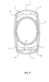
- the base includes a tubular casing external (1) in which an internal tube (3) is guided, using balls (7) in particular maintained by a cage (8).
- the part having elastic properties allowing it to make up for the play consists of a plate (4), for example of elastomeric material, fixed to the outer casing (1) and on which half of the balls (7) of the cage (8) rolls.
- the outer tubular envelope (1) defines a first volume of pace substantially rectangular extended by a column-shaped portion (2) protruding from a small side.
- the internal tube (3) is oval in shape, placed inside of the main rectangular-shaped portion of the external envelope (1).
- a plate (4) of elastic material occupies the small side opposite to that from from which the column (2) develops. This plate (4) follows the interior shape delimited by the external tubular envelope (1) in this zone, and it terminates to shift the internal wall towards the inside of the closed volume delimited by said envelope (1).
- the inner tube (3) is centered, close to the penetration of the ball, the interior of the rectangular interior volume defined between the two shoulders (5, 6) and the internal face of the plate (4).
- the four corners of this volume are occupied by balls (7) held by a plastic cage (8).
- These marbles (7) are arranged in rows parallel to the sliding axis, in this case perpendicular to the drawing plane.
- the balls are chosen so that their dimensions are such that the space they occupy, in combination with the dimensions of the inner tube (3), do not allow occupation of the actual interior volume such as previously defined, that is to say including the elastic plate (4), that by forced insertion.
- a plastic deformation of said plate (4) is product, symbolized by the portions of the balls (7) drawn in dotted lines level of their area of intersection (9) with the volume of the plate (4).
- the latter is made of a material selected for its properties elastic bands, the thickness of which is notably chosen to allow absorption of the residual play due to oversizing of the balls (7).
- the whole game is like this absorbed, without the need to deform the tube interior (3).
- Figure 4 shows a configuration also based on an elastic plate (4), the geometry of the external tubular casing (1) being however slightly different from that of the previous version, and corresponding to the configuration of Figures 1 and 2.
- the elastic piece (4 ') consists of a profile in spring steel, the ends (10, 10 ') of which form flat surfaces on which the balls are in support. These ends (10, 10 ') extend loops (11, 11 ') which provide the elastic effect to the piece, combined with intrinsically elastic properties of the material used.
- FIG. 6 proposes a solution in which a non-elastic part (12) leans on a plate (4 ") of material having substantially the same properties than that which is used for the solution of figure 1 for example also made of elastomer.
- the displacement of the lateral wings (13, 13 ') of the part hard (12) then results from the elastic properties of the plate (4 ").
Landscapes
- Engineering & Computer Science (AREA)
- General Engineering & Computer Science (AREA)
- Mechanical Engineering (AREA)
- Bearings For Parts Moving Linearly (AREA)
- Bending Of Plates, Rods, And Pipes (AREA)
- Aiming, Guidance, Guns With A Light Source, Armor, Camouflage, And Targets (AREA)
- Joints Allowing Movement (AREA)
- Monitoring And Testing Of Nuclear Reactors (AREA)
- Measuring Pulse, Heart Rate, Blood Pressure Or Blood Flow (AREA)
- Investigating Or Analyzing Materials By The Use Of Ultrasonic Waves (AREA)
- Pinball Game Machines (AREA)
- Prostheses (AREA)
Claims (9)
- System zur teleskopischen Führung eines Innenrohrs (3) in einer äußeren röhrenförmigen Hülle (1), mit Reihen von Kugeln (7), die in wenigstens einem Käfig (8) parallel zur Gleitachse angeordnet sind, wobei die Reihen durch Gruppierung in n Paare, durch die eine durch die Gleitachse verlaufende vertikale Medianebene verläuft, entgegengesetzte Wirkungen ausüben, wobei die Kugeln (7) auf der Außenwand des Innenrohrs (3) und auf zwei gegenüberliegenden Wänden, die sich auf Seiten der äußeren Hülle (1) befinden, rollen können, wobei die Wände zusammen eine Rollführung definieren, dadurch gekennzeichnet, dass eine der zwei Wände, die mit n Reihen benachbarter Kugeln (7) aus verschiedenen Paaren zusammenwirkt, zu einem Teil (4, 4', 4") gehört, wovon wenigstens ein Abschnitt aus einem elastischen Werkstoff besteht, wobei das Teil (4, 4', 4") mit der äußeren röhrenförmigen Hülle (1) fest verbunden ist und der elastische Werkstoff die n Reihen von Kugeln gegen das Innenrohr (3) drängt.
- System zur teleskopischen Führung eines Innenrohrs (3) in einer äußeren röhrenförmigen Hülle (1) nach dem vorhergehenden Anspruch, dadurch gekennzeichnet, dass das elastische Teil eine elastomere Platte (4) ist.
- System zur teleskopischen Führung eines Innenrohrs (3) in einer äußeren röhrenförmigen Hülle (1) nach Anspruch 1, dadurch gekennzeichnet, dass das Teil ein Profilelement (4') mit Blattfedern (10, 10') ist, wobei die Kugeln (7) in Kontakt mit diesen angeordnet sind.
- System zur teleskopischen Führung eines Innenrohrs (3) in einer äußeren röhrenförmigen Hülle (1) nach Anspruch 3, dadurch gekennzeichnet, dass das Profilelement (4') aus Federstahl besteht.
- System zur teleskopischen Führung eines Innenrohrs (3) in einer äußeren röhrenförmigen Hülle (1) nach Anspruch 1, dadurch gekennzeichnet, dass das Teil ein nicht elastisches Abstützorgan (12) für jene Kugeln aufweist, die mit einer elastischen Platte (4") zusammenwirken, die in Kontakt mit der äußeren röhrenförmigen Hülle (1) angeordnet ist.
- System zur teleskopischen Führung eines Innenrohrs (3) in einer äußeren röhrenförmigen Hülle (1) nach Anspruch 5, dadurch gekennzeichnet, dass die elastische Platte (4") aus einem Elastomer besteht.
- System zur teleskopischen Führung eines Innenrohrs in einer äußeren röhrenförmigen Hülle (1) nach einem der vorhergehenden Ansprüche, dadurch gekennzeichnet, dass der Käfig (8) vier axiale Reihen von Kugeln (7) aufweist, die in Kontakt mit dem Innenrohr (3) angeordnet sind.
- System zur teleskopischen Führung eines Innenrohrs (3) in einer äußeren röhrenförmigen Hülle (1) nach einem der vorhergehenden Ansprüche, dadurch gekennzeichnet, dass das Innenrohr (3) einen ovalen Verlauf hat.
- Anwendung eines Führungssystems nach einem der vorhergehenden Ansprüche auf ein Fußgestell eines tischartigen Möbelstücks.
Priority Applications (5)
| Application Number | Priority Date | Filing Date | Title |
|---|---|---|---|
| ES01440187T ES2225448T3 (es) | 2001-06-21 | 2001-06-21 | Sistema de guiado telescopico de untubo interno en una envolvente tubular extrema. |
| DE60105140T DE60105140T2 (de) | 2001-06-21 | 2001-06-21 | Teleskopische Führungseinrichtung eines inneren Rohres in einer äusseren rohrförmigen Umhüllung |
| AT01440187T ATE274654T1 (de) | 2001-06-21 | 2001-06-21 | Teleskopische führungseinrichtung eines inneren rohres in einer äusseren rohrförmigen umhüllung |
| PT01440187T PT1270972E (pt) | 2001-06-21 | 2001-06-21 | Sistema de guia telescopico de um tubo interno num involucro tubular externo |
| EP01440187A EP1270972B1 (de) | 2001-06-21 | 2001-06-21 | Teleskopische Führungseinrichtung eines inneren Rohres in einer äusseren rohrförmigen Umhüllung |
Applications Claiming Priority (1)
| Application Number | Priority Date | Filing Date | Title |
|---|---|---|---|
| EP01440187A EP1270972B1 (de) | 2001-06-21 | 2001-06-21 | Teleskopische Führungseinrichtung eines inneren Rohres in einer äusseren rohrförmigen Umhüllung |
Publications (2)
| Publication Number | Publication Date |
|---|---|
| EP1270972A1 EP1270972A1 (de) | 2003-01-02 |
| EP1270972B1 true EP1270972B1 (de) | 2004-08-25 |
Family
ID=8183242
Family Applications (1)
| Application Number | Title | Priority Date | Filing Date |
|---|---|---|---|
| EP01440187A Expired - Lifetime EP1270972B1 (de) | 2001-06-21 | 2001-06-21 | Teleskopische Führungseinrichtung eines inneren Rohres in einer äusseren rohrförmigen Umhüllung |
Country Status (5)
| Country | Link |
|---|---|
| EP (1) | EP1270972B1 (de) |
| AT (1) | ATE274654T1 (de) |
| DE (1) | DE60105140T2 (de) |
| ES (1) | ES2225448T3 (de) |
| PT (1) | PT1270972E (de) |
Families Citing this family (2)
| Publication number | Priority date | Publication date | Assignee | Title |
|---|---|---|---|---|
| DE102005037528B4 (de) * | 2005-08-09 | 2014-01-09 | Schaeffler Technologies AG & Co. KG | Wellenkupplung zur Drehmomentübertragung |
| CA2568078C (en) | 2006-11-14 | 2014-03-18 | Unifor S.P.A. | Telescopic table support |
Citations (1)
| Publication number | Priority date | Publication date | Assignee | Title |
|---|---|---|---|---|
| DE19623437A1 (de) * | 1996-06-12 | 1998-01-02 | Herbert Gruettner Gmbh & Co Kg | Teleskopführung |
Family Cites Families (4)
| Publication number | Priority date | Publication date | Assignee | Title |
|---|---|---|---|---|
| IT7223966U1 (it) * | 1972-12-07 | 1974-06-07 | Philips Spa | Dispositivo di sostegno a telescopio con ripresa automatica dei giochi |
| DE2656822A1 (de) * | 1976-12-15 | 1978-06-22 | Markus Spoetzl | Waelzlagerung |
| DE3124927A1 (de) * | 1981-06-25 | 1983-03-31 | INA Wälzlager Schaeffler KG, 8522 Herzogenaurach | Wellenkupplung zur drehmomentuebertragung |
| DE3813422A1 (de) * | 1988-04-21 | 1989-11-02 | Lemfoerder Metallwaren Ag | Teleskopierbare lenkwelle fuer kraftfahrzeuge |
-
2001
- 2001-06-21 AT AT01440187T patent/ATE274654T1/de not_active IP Right Cessation
- 2001-06-21 PT PT01440187T patent/PT1270972E/pt unknown
- 2001-06-21 ES ES01440187T patent/ES2225448T3/es not_active Expired - Lifetime
- 2001-06-21 EP EP01440187A patent/EP1270972B1/de not_active Expired - Lifetime
- 2001-06-21 DE DE60105140T patent/DE60105140T2/de not_active Expired - Lifetime
Patent Citations (1)
| Publication number | Priority date | Publication date | Assignee | Title |
|---|---|---|---|---|
| DE19623437A1 (de) * | 1996-06-12 | 1998-01-02 | Herbert Gruettner Gmbh & Co Kg | Teleskopführung |
Also Published As
| Publication number | Publication date |
|---|---|
| ES2225448T3 (es) | 2005-03-16 |
| ATE274654T1 (de) | 2004-09-15 |
| DE60105140D1 (de) | 2004-09-30 |
| EP1270972A1 (de) | 2003-01-02 |
| PT1270972E (pt) | 2004-12-31 |
| DE60105140T2 (de) | 2005-09-08 |
Similar Documents
| Publication | Publication Date | Title |
|---|---|---|
| FR2717994A1 (fr) | Etagère à surface variable. | |
| FR2917682A1 (fr) | Actionneur pour un vehicule automobile, comprenant un carter d'engrenage | |
| EP1270972B1 (de) | Teleskopische Führungseinrichtung eines inneren Rohres in einer äusseren rohrförmigen Umhüllung | |
| FR3120507A1 (fr) | Table à rallonge centrale | |
| FR2965754A1 (fr) | Roulette amortisseur | |
| CH666169A5 (fr) | Element d'armature pour structure de meubles. | |
| WO2013131982A1 (fr) | Bijou annulaire de diametre interne ajustable | |
| FR3041722A1 (fr) | Cage pour roulement a billes pourvue d'un fil et d'intercalaires rapportes | |
| EP4223185B1 (de) | Stapelbarer reihenstuhl | |
| FR3072432A1 (fr) | Boitier de transmission et engin equipe d'un tel boitier | |
| FR2726623A1 (fr) | Boite de vitesses | |
| BE566193A (de) | ||
| FR2851540A1 (fr) | Poussoir pour direction a cremaillere de vehicule automobile | |
| FR2784721A1 (fr) | Structure de diedre et procede de fabrication de cette structure | |
| EP0344059B1 (de) | Rotierende Zahnradvorrichtung zur Förderung einer Flüssigkeit | |
| FR3064709A1 (fr) | Galets a rouleaux pour l'entrainement en rotation d'une roue d'aeronef | |
| FR2578298A1 (fr) | Elements assemblables pour la realisation de meubles de rangement | |
| FR2829371A1 (fr) | Dispositif de suspension de deux lattes | |
| FR2717663A1 (fr) | Pupitre perfectionne. | |
| FR3105773A1 (fr) | fourreau de colonne de direction comportant un Système de réglage d’une position relative entre deux tubes | |
| EP1266594A1 (de) | Tisch mit eingebautem einschiebbarem Sitze | |
| CA3085822A1 (en) | Shaft assembly for an aircraft turbine engine | |
| FR3156020A3 (fr) | Élément pivot pour lit montable et démontable | |
| FR2899662A1 (fr) | Organe elastique de suspension en matiere plastique de type ressort, rotule ou similaire pour sommier, matelas ou siege | |
| FR2640861A1 (de) |
Legal Events
| Date | Code | Title | Description |
|---|---|---|---|
| PUAI | Public reference made under article 153(3) epc to a published international application that has entered the european phase |
Free format text: ORIGINAL CODE: 0009012 |
|
| 17P | Request for examination filed |
Effective date: 20010714 |
|
| AK | Designated contracting states |
Kind code of ref document: A1 Designated state(s): AT BE CH CY DE DK ES FI FR GB GR IE IT LI LU MC NL PT SE TR |
|
| AX | Request for extension of the european patent |
Free format text: AL;LT;LV;MK;RO;SI |
|
| 17Q | First examination report despatched |
Effective date: 20030227 |
|
| AKX | Designation fees paid |
Designated state(s): AT BE CH CY DE DK ES FI FR GB GR IE IT LI LU MC NL PT SE TR |
|
| GRAP | Despatch of communication of intention to grant a patent |
Free format text: ORIGINAL CODE: EPIDOSNIGR1 |
|
| GRAS | Grant fee paid |
Free format text: ORIGINAL CODE: EPIDOSNIGR3 |
|
| GRAA | (expected) grant |
Free format text: ORIGINAL CODE: 0009210 |
|
| AK | Designated contracting states |
Kind code of ref document: B1 Designated state(s): AT BE CH CY DE DK ES FI FR GB GR IE IT LI LU MC NL PT SE TR |
|
| PG25 | Lapsed in a contracting state [announced via postgrant information from national office to epo] |
Ref country code: TR Free format text: LAPSE BECAUSE OF FAILURE TO SUBMIT A TRANSLATION OF THE DESCRIPTION OR TO PAY THE FEE WITHIN THE PRESCRIBED TIME-LIMIT Effective date: 20040825 Ref country code: FI Free format text: LAPSE BECAUSE OF FAILURE TO SUBMIT A TRANSLATION OF THE DESCRIPTION OR TO PAY THE FEE WITHIN THE PRESCRIBED TIME-LIMIT Effective date: 20040825 Ref country code: IE Free format text: LAPSE BECAUSE OF FAILURE TO SUBMIT A TRANSLATION OF THE DESCRIPTION OR TO PAY THE FEE WITHIN THE PRESCRIBED TIME-LIMIT Effective date: 20040825 Ref country code: AT Free format text: LAPSE BECAUSE OF FAILURE TO SUBMIT A TRANSLATION OF THE DESCRIPTION OR TO PAY THE FEE WITHIN THE PRESCRIBED TIME-LIMIT Effective date: 20040825 |
|
| REG | Reference to a national code |
Ref country code: GB Ref legal event code: FG4D Free format text: NOT ENGLISH |
|
| REG | Reference to a national code |
Ref country code: CH Ref legal event code: EP |
|
| REG | Reference to a national code |
Ref country code: IE Ref legal event code: FG4D Free format text: FRENCH |
|
| REF | Corresponds to: |
Ref document number: 60105140 Country of ref document: DE Date of ref document: 20040930 Kind code of ref document: P |
|
| PG25 | Lapsed in a contracting state [announced via postgrant information from national office to epo] |
Ref country code: DK Free format text: LAPSE BECAUSE OF FAILURE TO SUBMIT A TRANSLATION OF THE DESCRIPTION OR TO PAY THE FEE WITHIN THE PRESCRIBED TIME-LIMIT Effective date: 20041125 Ref country code: GR Free format text: LAPSE BECAUSE OF FAILURE TO SUBMIT A TRANSLATION OF THE DESCRIPTION OR TO PAY THE FEE WITHIN THE PRESCRIBED TIME-LIMIT Effective date: 20041125 Ref country code: SE Free format text: LAPSE BECAUSE OF FAILURE TO SUBMIT A TRANSLATION OF THE DESCRIPTION OR TO PAY THE FEE WITHIN THE PRESCRIBED TIME-LIMIT Effective date: 20041125 |
|
| GBT | Gb: translation of ep patent filed (gb section 77(6)(a)/1977) |
Effective date: 20041129 |
|
| REG | Reference to a national code |
Ref country code: PT Ref legal event code: SC4A Free format text: AVAILABILITY OF NATIONAL TRANSLATION Effective date: 20041027 |
|
| REG | Reference to a national code |
Ref country code: ES Ref legal event code: FG2A Ref document number: 2225448 Country of ref document: ES Kind code of ref document: T3 |
|
| REG | Reference to a national code |
Ref country code: IE Ref legal event code: FD4D |
|
| PG25 | Lapsed in a contracting state [announced via postgrant information from national office to epo] |
Ref country code: CY Free format text: LAPSE BECAUSE OF FAILURE TO SUBMIT A TRANSLATION OF THE DESCRIPTION OR TO PAY THE FEE WITHIN THE PRESCRIBED TIME-LIMIT Effective date: 20050621 Ref country code: LU Free format text: LAPSE BECAUSE OF NON-PAYMENT OF DUE FEES Effective date: 20050621 |
|
| PG25 | Lapsed in a contracting state [announced via postgrant information from national office to epo] |
Ref country code: MC Free format text: LAPSE BECAUSE OF NON-PAYMENT OF DUE FEES Effective date: 20050630 Ref country code: CH Free format text: LAPSE BECAUSE OF NON-PAYMENT OF DUE FEES Effective date: 20050630 Ref country code: LI Free format text: LAPSE BECAUSE OF NON-PAYMENT OF DUE FEES Effective date: 20050630 |
|
| PLBE | No opposition filed within time limit |
Free format text: ORIGINAL CODE: 0009261 |
|
| STAA | Information on the status of an ep patent application or granted ep patent |
Free format text: STATUS: NO OPPOSITION FILED WITHIN TIME LIMIT |
|
| 26N | No opposition filed |
Effective date: 20050526 |
|
| REG | Reference to a national code |
Ref country code: CH Ref legal event code: PL |
|
| PGFP | Annual fee paid to national office [announced via postgrant information from national office to epo] |
Ref country code: NL Payment date: 20090603 Year of fee payment: 9 |
|
| PGFP | Annual fee paid to national office [announced via postgrant information from national office to epo] |
Ref country code: IT Payment date: 20090622 Year of fee payment: 9 |
|
| REG | Reference to a national code |
Ref country code: HK Ref legal event code: WD Ref document number: 1054421 Country of ref document: HK |
|
| PGFP | Annual fee paid to national office [announced via postgrant information from national office to epo] |
Ref country code: PT Payment date: 20100604 Year of fee payment: 10 |
|
| PGFP | Annual fee paid to national office [announced via postgrant information from national office to epo] |
Ref country code: BE Payment date: 20100615 Year of fee payment: 10 |
|
| REG | Reference to a national code |
Ref country code: NL Ref legal event code: V1 Effective date: 20110101 |
|
| PG25 | Lapsed in a contracting state [announced via postgrant information from national office to epo] |
Ref country code: IT Free format text: LAPSE BECAUSE OF NON-PAYMENT OF DUE FEES Effective date: 20100621 |
|
| PG25 | Lapsed in a contracting state [announced via postgrant information from national office to epo] |
Ref country code: NL Free format text: LAPSE BECAUSE OF NON-PAYMENT OF DUE FEES Effective date: 20110101 |
|
| PGFP | Annual fee paid to national office [announced via postgrant information from national office to epo] |
Ref country code: ES Payment date: 20110624 Year of fee payment: 11 Ref country code: FR Payment date: 20110630 Year of fee payment: 11 |
|
| PGFP | Annual fee paid to national office [announced via postgrant information from national office to epo] |
Ref country code: GB Payment date: 20110620 Year of fee payment: 11 |
|
| PGFP | Annual fee paid to national office [announced via postgrant information from national office to epo] |
Ref country code: DE Payment date: 20110622 Year of fee payment: 11 |
|
| REG | Reference to a national code |
Ref country code: PT Ref legal event code: MM4A Free format text: LAPSE DUE TO NON-PAYMENT OF FEES Effective date: 20111221 |
|
| BERE | Be: lapsed |
Owner name: S.A. *STEELCASE Effective date: 20110630 |
|
| PG25 | Lapsed in a contracting state [announced via postgrant information from national office to epo] |
Ref country code: PT Free format text: LAPSE BECAUSE OF NON-PAYMENT OF DUE FEES Effective date: 20111221 |
|
| PG25 | Lapsed in a contracting state [announced via postgrant information from national office to epo] |
Ref country code: BE Free format text: LAPSE BECAUSE OF NON-PAYMENT OF DUE FEES Effective date: 20110630 |
|
| GBPC | Gb: european patent ceased through non-payment of renewal fee |
Effective date: 20120621 |
|
| REG | Reference to a national code |
Ref country code: FR Ref legal event code: ST Effective date: 20130228 |
|
| REG | Reference to a national code |
Ref country code: DE Ref legal event code: R119 Ref document number: 60105140 Country of ref document: DE Effective date: 20130101 |
|
| PG25 | Lapsed in a contracting state [announced via postgrant information from national office to epo] |
Ref country code: DE Free format text: LAPSE BECAUSE OF NON-PAYMENT OF DUE FEES Effective date: 20130101 Ref country code: GB Free format text: LAPSE BECAUSE OF NON-PAYMENT OF DUE FEES Effective date: 20120621 Ref country code: FR Free format text: LAPSE BECAUSE OF NON-PAYMENT OF DUE FEES Effective date: 20120702 |
|
| REG | Reference to a national code |
Ref country code: ES Ref legal event code: FD2A Effective date: 20131021 |
|
| PG25 | Lapsed in a contracting state [announced via postgrant information from national office to epo] |
Ref country code: ES Free format text: LAPSE BECAUSE OF NON-PAYMENT OF DUE FEES Effective date: 20120622 |