EP1270959B1 - Hydraulic tool having mechanical actuator with internal bypass valve - Google Patents
Hydraulic tool having mechanical actuator with internal bypass valve Download PDFInfo
- Publication number
- EP1270959B1 EP1270959B1 EP02447111A EP02447111A EP1270959B1 EP 1270959 B1 EP1270959 B1 EP 1270959B1 EP 02447111 A EP02447111 A EP 02447111A EP 02447111 A EP02447111 A EP 02447111A EP 1270959 B1 EP1270959 B1 EP 1270959B1
- Authority
- EP
- European Patent Office
- Prior art keywords
- ram
- mechanical actuator
- housing member
- conduit
- frame
- Prior art date
- Legal status (The legal status is an assumption and is not a legal conclusion. Google has not performed a legal analysis and makes no representation as to the accuracy of the status listed.)
- Expired - Lifetime
Links
Images


Classifications
-
- F—MECHANICAL ENGINEERING; LIGHTING; HEATING; WEAPONS; BLASTING
- F15—FLUID-PRESSURE ACTUATORS; HYDRAULICS OR PNEUMATICS IN GENERAL
- F15B—SYSTEMS ACTING BY MEANS OF FLUIDS IN GENERAL; FLUID-PRESSURE ACTUATORS, e.g. SERVOMOTORS; DETAILS OF FLUID-PRESSURE SYSTEMS, NOT OTHERWISE PROVIDED FOR
- F15B7/00—Systems in which the movement produced is definitely related to the output of a volumetric pump; Telemotors
- F15B7/04—In which the ratio between pump stroke and motor stroke varies with the resistance against the motor
-
- B—PERFORMING OPERATIONS; TRANSPORTING
- B25—HAND TOOLS; PORTABLE POWER-DRIVEN TOOLS; MANIPULATORS
- B25B—TOOLS OR BENCH DEVICES NOT OTHERWISE PROVIDED FOR, FOR FASTENING, CONNECTING, DISENGAGING OR HOLDING
- B25B27/00—Hand tools, specially adapted for fitting together or separating parts or objects whether or not involving some deformation, not otherwise provided for
- B25B27/02—Hand tools, specially adapted for fitting together or separating parts or objects whether or not involving some deformation, not otherwise provided for for connecting objects by press fit or detaching same
- B25B27/10—Hand tools, specially adapted for fitting together or separating parts or objects whether or not involving some deformation, not otherwise provided for for connecting objects by press fit or detaching same inserting fittings into hoses
-
- F—MECHANICAL ENGINEERING; LIGHTING; HEATING; WEAPONS; BLASTING
- F15—FLUID-PRESSURE ACTUATORS; HYDRAULICS OR PNEUMATICS IN GENERAL
- F15B—SYSTEMS ACTING BY MEANS OF FLUIDS IN GENERAL; FLUID-PRESSURE ACTUATORS, e.g. SERVOMOTORS; DETAILS OF FLUID-PRESSURE SYSTEMS, NOT OTHERWISE PROVIDED FOR
- F15B15/00—Fluid-actuated devices for displacing a member from one position to another; Gearing associated therewith
- F15B15/18—Combined units comprising both motor and pump
-
- H—ELECTRICITY
- H01—ELECTRIC ELEMENTS
- H01R—ELECTRICALLY-CONDUCTIVE CONNECTIONS; STRUCTURAL ASSOCIATIONS OF A PLURALITY OF MUTUALLY-INSULATED ELECTRICAL CONNECTING ELEMENTS; COUPLING DEVICES; CURRENT COLLECTORS
- H01R43/00—Apparatus or processes specially adapted for manufacturing, assembling, maintaining, or repairing of line connectors or current collectors or for joining electric conductors
- H01R43/04—Apparatus or processes specially adapted for manufacturing, assembling, maintaining, or repairing of line connectors or current collectors or for joining electric conductors for forming connections by deformation, e.g. crimping tool
- H01R43/042—Hand tools for crimping
- H01R43/0427—Hand tools for crimping fluid actuated hand crimping tools
Definitions
- the present invention relates to hydraulic tools and, more particularly, to a hydraulic tool having a mechanical actuator.
- U.S. Patent No. 5,979,215 discloses a hydraulic compression tool with a rapid ram advance.
- the tool comprises a mechanical actuator which can directly push against a rear end of a ram.
- the ram is separately movable relative to the mechanical actuator.
- a bypass valve is provided in the conduit system of the tool to allow hydraulic fluid to bypass the mechanical actuator.
- the bypass valve is located spaced from the mechanical actuator.
- U.S. Patent No. 5,284,044 discloses a hydraulic wire joining device including a cylinder for clamping a wedge over at least two wires and a work fixture for transmitting a cylinder force to the wedge.
- the cylinder is a two-stage type of cylinders having respective first and second coaxial pistons.
- the first piston has passage means which has a pressure valve and which, upon opening at a second stage, provides a higher fluid pressure level needed for the final crimping of the wedge. No reservoir nor pump arrangements are disclosed in this document.
- a hydraulic compression tool having a frame, a hydraulic fluid reservoir on the frame, a ram movably connected to the frame, a conduit system in the frame between the reservoir and the ram, a pump provided in the conduit system, a mechanical actuator provided in the conduit system for contacting the ram, and a bypass valve in the conduit system between a rear end of the ram and a channel of the conduit system to the rear end of the mechanical actuator.
- the conduit system is adapted to conduit fluid from the pump against both the rear end of the ram and a rear end of the mechanical actuator.
- the bypass valve is located, at least partially, in a housing member of the mechanical actuator.
- the housing member comprises a conduit channel extending from a rear end to a front end of the housing member, and a hole extending through the front end from the conduit channel.
- the front end of the housing member comprises an aperture from the conduit channel through the housing member to a lateral side of the housing member.
- a method of manufacturing a hydraulic compression tool comprising steps of providing a mechanical actuator assembly, the mechanical actuator assembly having a housing member with a hydraulic fluid channel therethrough, and a bypass valve located in the housing member at the channel; providing a laterally extending aperture through the housing member from the hydraulic fluid channel to a lateral side of the housing member; providing the housing member with a hole extending through the front end of the housing member from the conduit channel; connecting the mechanical actuator assembly to a frame of the tool, the frame including a conduit system, the housing member of the mechanical actuator assembly being slidingly located in a portion of the conduit system; and connecting a ram to the frame.
- the ram is movable on the frame and is adapted to be directly contacted by the mechanical actuator assembly.
- the ram is movable relative to the housing member of the mechanical actuator assembly.
- a method of advancing a ram in a hydraulic compression tool comprising steps of actuating a pump of the tool to move the ram relative to a frame of the tool at a first rate of movement by pushing hydraulic fluid against a first pushing surface of a mechanical actuator to push the ram forward, the mechanical actuator being located against the ram; and actuating the pump to move the ram relative to the frame at a second slower rate of movement by pushing hydraulic fluid against a second larger pushing surface of the ram to push the ram forward.
- the mechanical actuator has a conduit channel with a bypass valve therein.
- the step of actuating the pump of the tool to move the ram relative to the frame at the second lower rate of movement includes hydraulic fluid passing through the conduit channel and the bypass valve of the mechanical actuator to the second larger pushing surface of the ram.
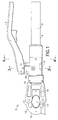
- FIG. 1 there is shown a side elevational view of a hydraulic compression tool 2 incorporating features of the present invention.
- a hydraulic compression tool 2 incorporating features of the present invention.
- the tool 2 generally comprises a first handle 4 having a fluid reservoir 8 therein, a second handle 6, a body 10 and a compression head 12.
- the reservoir 8 is generally capable of holding a supply of hydraulic fluid, such as oil, and capable of supplying the fluid to the body 10.
- the reservoir 8 is partially formed from a portion of the body 10.
- the second handle 6 is pivotably mounted to the body 10 for operating a hydraulic pump 24.
- the tool 2 is similar to the tools shown in the U.S. Patent No. 5,979,215 .
- U.S. Patent Nos. 4,942,757 and 4,947,672 also disclosed hydraulic tools with movable rams.
- the compression head 12 generally comprises a cylinder body 14 with a ram or piston 16 movably mounted therein and a frame 13 with an anvil or clamping section 15.
- the clamping section 15 and the ram 16 each also comprises means for mounting two dies (not shown) for compressing articles (such as metal electrical connectors) onto elements (such as electrical wires or cables). These dies are removable from the compression head 12 such that the compression head can accommodate different types of dies for different connectors.
- the compression tool might be a die-less tool.
- features of the present invention could be used in any suitable type of hydraulic tool, such as a cutting tool, or a battery powered hydraulic tool.
- the handles 4,6 can be manipulated to operate the hydraulic pump 24 for providing fluid from the fluid reservoir 8 in the first handle 4 to provide high pressure hydraulics to move the ram 16 forward relative to the body 10.
- the body 10 generally comprises a frame 28, the hydraulic pump 24, a relief valve 26, a release valve 32 (see Fig. 5 ), and a plurality of conduits forming a supply conduit system and a return conduit system as will be described below.
- the frame 28 has a pivot arm 30 which is provided for pivotably connecting the second handle 6 to the body 10.
- the conduit system generally comprises a suction conduit 34 (see Fig. 6 ), return conduits 38-40 (see Figs. 2 and 5 ), supply conduits 42-45 (see Figs. 2-5 ) and an actuator conduit 46 (see Fig. 2 ).
- Conduit 47 functions both as part of the supply and return systems.
- the suction conduit 34 has sections 34a, 34b, 34c and 34d.
- a check valve 52 is located in section 34b between sections 34a, and 34d.
- a check valve 54 is located at the end of section 34c.
- a hydraulic fluid filter 53 is located at the start of the suction conduit 34 at the reservoir 8.
- the supply conduit 42 is in communication with the pump 24 and has the check valve 54 therein.
- the supply conduit 43 extends between the supply conduit 42 and the supply conduit 44.
- the supply conduit 43 has a check valve 60 therein.
- the supply conduit 44 extends to the conduit 45 which, in turn, extends to the conduit 47.
- the conduit 47 is in communication with the actuator conduit 46.
- the actuator conduit 46 has an enlarged portion which forms a receiving area for a mechanical actuator assembly 66.
- return conduit 38 extends from the conduit 47 to the relief valve 26.
- a check valve 56 is located in the return conduit 39.
- Relief valve 26 automatically temporarily opens when excessive hydraulic fluid pressure is present in the conduit system; such as about 620 bar (9000 psi) for example. The hydraulic fluid can flow through the relief valve 26 back to the reservoir 8 until the pressure drops; at which point the relief valve closes again.
- Return conduit 39 extends from the ram hydraulic chamber 64 of the cylinder body 14 to the conduit 47.
- return conduit 40 extends from the release valve 32 back to the reservoir 8.
- the release valve 32 comprises a plunger 138 and a check valve 110 in communication with the channel 44.
- the check valve 110 is opened such that hydraulic fluid can flow out of the ram hydraulic chamber 64 and out of the actuator conduit 46 through the channels 47, 45, 44 and 40 back to the reservoir 8.
- the handle 6 has a trigger system 140 for moving the plunger 138.
- the trigger system 140 generally comprises a trigger 142, a connecting rod 144, and an actuator 146.
- the trigger 142 is pivotably connected to the handle 6.
- the actuator 146 is also pivotably connected to the handle 6.
- the connecting rod 144 is connected between the trigger 142 and the actuator 146.
- the trigger system 140 comprises a spring (not shown) which biases the system in a deactuated position as shown in Figs. 2 and 5 .
- a user can depress the trigger 142 to move the connecting rod 144 which, in turn, moves the bottom end 148 of the actuator 146 to a position directly above the plunger 138.
- the bottom end 148 of the actuator 146 depresses the plunger 138 to move the check valve 110 into an open position. This allows hydraulic fluid to flow out of the conduit 44 and into the conduit 40, and back to the reservoir 8.
- the actuator 146 is disengaged from the plunger 138.
- the check valve 110 returns back to its closed position moving the plunger 138 back to its outward position.
- any suitable type of release system or system for actuating the release system could be provided.
- the mechanical actuator assembly 66 generally comprises a housing member 70 and a bypass valve 72.
- the housing member 70 has a rear end 74, a front end 76, and a conduit channel 78 therebetween.
- the conduit channel 78 has a first section 78a and a second section 78b.
- the first section 78a has a smaller cross sectional size than the second section 78b.
- a valve seat 80 is provided at the junction between the first section 78a and the second section 78b.
- the housing member 70 has an annular recess 82 with an O-ring seal 84 therein. In this embodiment, the housing member 70 has a general T shape.
- the housing member 70 also comprises apertures or holes 86 extending from the conduit channel 78 to a lateral side of the housing member at a location behind the enlarged head at the front end 76.
- the housing member could have any suitable shape.
- the conduit channel in the housing member could also have any suitable type of shape or configuration.
- the bypass valve 72 generally comprises a ball 88 and a spring 90.
- the spring 90 is a coil spring.
- any suitable type of spring could be provided.
- the valve could have a movable closure member which does not have a ball shape, and/or any suitable biasing or valve opening/closing system could be provided.
- the bypass valve 72 is located in the second section 78b of the conduit channel.
- a valve retainer 92 is fixedly located in the front entrance to the second section 78b.
- An end of the spring 90 is located against the valve retainer 92.
- the opposite end of the spring 90 is located against the ball 88.
- the ball 88 is biased by the spring 90 towards the valve seat 80.
- the rear end of the ram 16 comprises a pocket 94.
- a surface 96 of the rear end at the pocket 94 is adapted to be contacted by the front end 76 of the housing member 70.
- the ram 16 comprises surfaces 96,98 and 100 at its rear end which form a second relatively larger hydraulic fluid pushing surface.
- the rear end of the ram 16 also comprises an annular recess 104 having an O-ring seal 106 therein.
- the rear end of the ram 16 is slidable in the ram hydraulic chamber 64 between its rear position as shown in Fig. 2 and a forward position.
- the tool 2 has various different modes of operation.
- a user places an item (such as an electrical connector and a conductor) in the receiving area 17 between the ram 16 and the clamping section 15.
- the user then pivots the handle 6 back-and-forth relative to the handle 4.
- This causes the pump 24 to move in and out relative to the frame 28.
- suction or negative pressure is created in the conduit 42.
- This suction is transmitted through the supply conduit 34 to suck or draw hydraulic fluid from the reservoir 8 into the area of the pump 24.
- the check valve 54 closes and hydraulic fluid is pushed through the channels 42-45,47 and into the actuator channel 46.
- the tool 2 uses a system to move the ram 16 at two different rates of movement; depending upon hydraulic fluid pressure in the supply conduit system.
- the two different rates of movement occurs for a same stroke of the pump 24 and a same relative movement of the handles 4,6.
- the ram movement system first moves the ram 16 forward relatively quickly. This occurs until resistance is encountered by the ram 16 when the ram makes contact with an article in the compression head. Then the ram 16 moves forward relatively slowly, but with greater force. In both situations, both rates of movement are provided by the same motion of the pump 24.
- the hydraulic fluid pumped into the actuator channel 46 moves the mechanical actuator assembly 66 forward relative to the frame 28. Because of the contact between the front end 96 of the housing member 70 and the surface 96 at the rear end of the ram 16, the ram 16 is pushed forward by the mechanical actuator assembly 66.
- the first rate of movement uses hydraulic pressure to move the actuator assembly 66 forward which, in turn, directly push against and moves the ram 16 forward. This provides a relatively fast forward movement of the ram 16. Hydraulic fluid is also sucked or drawn past the check valve 52 and through the section 34d of the suction conduit 34 into the ram hydraulic chamber 64 as the ram 16 moves forward. This prevents a vacuum behind the rear end of the ram 16 from forming to thereby prevent such a vacuum from stopping forward movement of the ram 16.
- the pump 24 still functions in the same manner of moving in and out, however, the ram 16 is no longer push forward only by the mechanical actuator assembly 66. Instead, the ram 16 is now pushed forward by hydraulic fluid pressure pushing directly against its rear end surface 96,98 and 100, and by the mechanical actuator since the pressure in chamber 46 is slightly greater than chamber 64.
- hydraulic pressure in the conduit 46 and section 78a is sufficiently large to push the bypass valve 72 to an open position and allow the hydraulic fluid to flow through the bypass valve and out the holes 86, 87 directly into the ram hydraulic chamber 64 behind the rear end of the ram 16.
- the ram 16 moves forward at a slower rate of movement in the second mode of operation than in the first mode of operation since there is considerable volume to fill/compress.
- the relief valve 26 opens during the inward stroke of the pump 24. Therefore, further forward movement of the ram 16 is automatically stopped. The user can feel a difference in movement of the handle 16 and also detects an audible pop. With these occurrences, the user can thereby recognize when the relief valve 26 opens, and can thus recognize that compression or crimping of the connector has completed. The user can then actuate the trigger system 140 to move the release valve 32 to an open position and the spring 103 can bias the ram 16 back to its rear position. Hydraulic fluid in the ram hydraulic chamber 64 can flow back to the reservoir 8 through the channels 39,47,45,44 and 40.
- the mechanical actuator assembly 66 comprises a channel in its housing member and a bypass valve which permits selective flow of fluid through the assembly. Because the bypass valve is located inside the housing member 70, this provides additional space in the frame 28 that otherwise would need to be occupied by a separate bypass valve; as in the U.S. Patent No. 5,979,215 .
- the present invention provides a combined mechanical actuator and bypass valve in a single assembly which takes up less space than in the prior art. Because the mechanical actuator assembly 66 takes up less space than in the prior art, the frame 28 can be made smaller. This can reduce the weight of the tool. This also simplifies or reduces the number of conduits that need to be provided in the conduit system. This can reduce the cost of manufacturing the frame 28.
- This assembly of a combined mechanical actuator and bypass valve as a single subassembly component also provides another feature.
- the bypass valve can be adjusted external to the tool as a subassembly. This can allow for a much more precise and relatively easy adjustment of the bypass valve than in the prior art.
- Another feature of the present invention is in regard to the hydraulic circuitry or conduit system.
- the tool has two suction conduits (104,106) and two check valves (128, 136); one for each suction conduit.
- the present invention can have a single suction conduit 34 from the reservoir 8 and check valves 52, 54 at different sections of the single suction conduit. This permits the use of one intake filter 53 at the reservoir end of the tool.
- the mechanical actuator assembly 66 could be coaxially mounted in a spring holder for holding the compression spring 103.
- the spring 103 could be located inside the ram coaxially arranged between the ram and the spring holder.
- the mechanical actuator assembly 66 could be slidably plugged into a receiving area in a front end of the spring holder.
- the spring holder could be stationarily mounted to the pump body, such as by threads.
- the mechanical actuator assembly 66 could be movably mounted inside the spring holder to extend out a front end of the spring holder.
- the spring holder could have a fluid conduit which connects the conduit channel 78 to the conduit system in the pump body. Such an arrangement could reduce the size of the tool by reducing the length of the tool at the area of the ram/spring-holder/mechanical-actuator-assembly.
- the mechanical actuator assembly 66 could be used with any other suitable type of components, or be modified to be used with any other suitable types of hydraulic compression tool components.
Description
- The present invention relates to hydraulic tools and, more particularly, to a hydraulic tool having a mechanical actuator.
-
U.S. Patent No. 5,979,215 discloses a hydraulic compression tool with a rapid ram advance. The tool comprises a mechanical actuator which can directly push against a rear end of a ram. The ram is separately movable relative to the mechanical actuator. A bypass valve is provided in the conduit system of the tool to allow hydraulic fluid to bypass the mechanical actuator. The bypass valve is located spaced from the mechanical actuator. -
U.S. Patent No. 5,284,044 discloses a hydraulic wire joining device including a cylinder for clamping a wedge over at least two wires and a work fixture for transmitting a cylinder force to the wedge. The cylinder is a two-stage type of cylinders having respective first and second coaxial pistons. The first piston has passage means which has a pressure valve and which, upon opening at a second stage, provides a higher fluid pressure level needed for the final crimping of the wedge. No reservoir nor pump arrangements are disclosed in this document. - There is a desire to provide a hydraulic compression tool which has additional space within its main body, but without increasing the size of the main body. There is also a desire to permit a bypass valve for a hydraulic compression tool to be relatively precisely adjusted external to the tool. There is also a desire to provide a hydraulic compression tool bypass valve as a subassembly. There is also a desire to reduce complexity of the hydraulic conduit system in the main body of a hydraulic compression tool.
- In accordance with one aspect of the present invention, a hydraulic compression tool is provided having a frame, a hydraulic fluid reservoir on the frame, a ram movably connected to the frame, a conduit system in the frame between the reservoir and the ram, a pump provided in the conduit system, a mechanical actuator provided in the conduit system for contacting the ram, and a bypass valve in the conduit system between a rear end of the ram and a channel of the conduit system to the rear end of the mechanical actuator. The conduit system is adapted to conduit fluid from the pump against both the rear end of the ram and a rear end of the mechanical actuator. The bypass valve is located, at least partially, in a housing member of the mechanical actuator.
- The housing member comprises a conduit channel extending from a rear end to a front end of the housing member, and a hole extending through the front end from the conduit channel. The front end of the housing member comprises an aperture from the conduit channel through the housing member to a lateral side of the housing member.
- In accordance with one method of the present invention, a method of manufacturing a hydraulic compression tool is provided comprising steps of providing a mechanical actuator assembly, the mechanical actuator assembly having a housing member with a hydraulic fluid channel therethrough, and a bypass valve located in the housing member at the channel; providing a laterally extending aperture through the housing member from the hydraulic fluid channel to a lateral side of the housing member; providing the housing member with a hole extending through the front end of the housing member from the conduit channel; connecting the mechanical actuator assembly to a frame of the tool, the frame including a conduit system, the housing member of the mechanical actuator assembly being slidingly located in a portion of the conduit system; and connecting a ram to the frame. The ram is movable on the frame and is adapted to be directly contacted by the mechanical actuator assembly. The ram is movable relative to the housing member of the mechanical actuator assembly.
- In accordance with another method of the present invention, a method of advancing a ram in a hydraulic compression tool is provided comprising steps of actuating a pump of the tool to move the ram relative to a frame of the tool at a first rate of movement by pushing hydraulic fluid against a first pushing surface of a mechanical actuator to push the ram forward, the mechanical actuator being located against the ram; and actuating the pump to move the ram relative to the frame at a second slower rate of movement by pushing hydraulic fluid against a second larger pushing surface of the ram to push the ram forward. The mechanical actuator has a conduit channel with a bypass valve therein. The step of actuating the pump of the tool to move the ram relative to the frame at the second lower rate of movement includes hydraulic fluid passing through the conduit channel and the bypass valve of the mechanical actuator to the second larger pushing surface of the ram.
- The foregoing aspects and other features of the present invention are explained in the following description, taken in connection with the accompanying drawings, wherein:
-
Fig. 1 is a side elevational view of a hydraulic compression tool incorporating features of the present invention; -
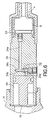
Fig. 2 is a partial cross sectional view of the tool shown inFig. 1 ; -
Fig. 2A is an enlarged cross sectional view of a portion of the tool shown inFig. 2 ; -
Fig. 2B is a partial cross sectional view of the tool as shown inFig. 2 with the ram moved forward separately from the mechanical actuator assembly; -
Fig. 3 is a cross sectional view of the tool shown inFig. 1 taken along line 3-3; -
Fig. 4 is a cross sectional view of the tool shown inFig. 1 taken along line 4-4 ; -
Fig. 5 is a cross sectional view of the tool shown inFig. 4 taken along line 5-5; and -
Fig. 6 is a cross sectional view of the tool shown inFig. 4 taken along line 6-6. - Referring to
Fig. 1 , there is shown a side elevational view of ahydraulic compression tool 2 incorporating features of the present invention. Although the present invention will be described with reference to the single embodiment shown in the drawings, it should be understood that the present invention can be embodied in many alternate forms of embodiments. In addition, any suitable size, shape or type of elements or materials could be used. - The
tool 2 generally comprises afirst handle 4 having afluid reservoir 8 therein, asecond handle 6, abody 10 and acompression head 12. Thereservoir 8 is generally capable of holding a supply of hydraulic fluid, such as oil, and capable of supplying the fluid to thebody 10. In the embodiment shown, thereservoir 8 is partially formed from a portion of thebody 10. Thesecond handle 6 is pivotably mounted to thebody 10 for operating ahydraulic pump 24. Thetool 2 is similar to the tools shown in theU.S. Patent No. 5,979,215 .U.S. Patent Nos. 4,942,757 and4,947,672 also disclosed hydraulic tools with movable rams. - The
compression head 12 generally comprises acylinder body 14 with a ram orpiston 16 movably mounted therein and aframe 13 with an anvil orclamping section 15. Theclamping section 15 and theram 16 each also comprises means for mounting two dies (not shown) for compressing articles (such as metal electrical connectors) onto elements (such as electrical wires or cables). These dies are removable from thecompression head 12 such that the compression head can accommodate different types of dies for different connectors. However, in an alternate embodiment, the compression tool might be a die-less tool. In addition, features of the present invention could be used in any suitable type of hydraulic tool, such as a cutting tool, or a battery powered hydraulic tool. - The
handles hydraulic pump 24 for providing fluid from thefluid reservoir 8 in thefirst handle 4 to provide high pressure hydraulics to move theram 16 forward relative to thebody 10. Referring also toFig. 2 , thebody 10 generally comprises aframe 28, thehydraulic pump 24, arelief valve 26, a release valve 32 (seeFig. 5 ), and a plurality of conduits forming a supply conduit system and a return conduit system as will be described below. Theframe 28 has apivot arm 30 which is provided for pivotably connecting thesecond handle 6 to thebody 10. - Referring now to all the figures, the conduit system generally comprises a suction conduit 34 (see
Fig. 6 ), return conduits 38-40 (seeFigs. 2 and5 ), supply conduits 42-45 (seeFigs. 2-5 ) and an actuator conduit 46 (seeFig. 2 ). Conduit 47 functions both as part of the supply and return systems. As seen best inFigs. 3 and6 , thesuction conduit 34 hassections check valve 52 is located insection 34b betweensections check valve 54 is located at the end ofsection 34c. Ahydraulic fluid filter 53 is located at the start of thesuction conduit 34 at thereservoir 8. - The
supply conduit 42 is in communication with thepump 24 and has thecheck valve 54 therein. As seen inFigs. 3 and5 , thesupply conduit 43 extends between thesupply conduit 42 and thesupply conduit 44. Thesupply conduit 43 has acheck valve 60 therein. As seen inFigs. 4 ,5 and2 , thesupply conduit 44 extends to theconduit 45 which, in turn, extends to theconduit 47. Theconduit 47 is in communication with theactuator conduit 46. Theactuator conduit 46 has an enlarged portion which forms a receiving area for amechanical actuator assembly 66. - As seen best in
Fig. 2 , returnconduit 38 extends from theconduit 47 to therelief valve 26. Acheck valve 56 is located in thereturn conduit 39.Relief valve 26 automatically temporarily opens when excessive hydraulic fluid pressure is present in the conduit system; such as about 620 bar (9000 psi) for example. The hydraulic fluid can flow through therelief valve 26 back to thereservoir 8 until the pressure drops; at which point the relief valve closes again. Returnconduit 39 extends from the ramhydraulic chamber 64 of thecylinder body 14 to theconduit 47. - As seen best in
Fig. 5 , returnconduit 40 extends from therelease valve 32 back to thereservoir 8. Therelease valve 32 comprises aplunger 138 and acheck valve 110 in communication with thechannel 44. When theplunger 138 is depressed, thecheck valve 110 is opened such that hydraulic fluid can flow out of the ramhydraulic chamber 64 and out of theactuator conduit 46 through thechannels reservoir 8. - Although the supply and return conduit systems have been described in detail above, in alternate embodiments any suitable type of conduit system could be provided in the
body 10 of the tool. - As seen in
Figs. 2 and5 , thehandle 6 has atrigger system 140 for moving theplunger 138. Thetrigger system 140 generally comprises atrigger 142, a connectingrod 144, and anactuator 146. Thetrigger 142 is pivotably connected to thehandle 6. Theactuator 146 is also pivotably connected to thehandle 6. The connectingrod 144 is connected between thetrigger 142 and theactuator 146. In a preferred embodiment, thetrigger system 140 comprises a spring (not shown) which biases the system in a deactuated position as shown inFigs. 2 and5 . - A user can depress the
trigger 142 to move the connectingrod 144 which, in turn, moves thebottom end 148 of theactuator 146 to a position directly above theplunger 138. When thehandle 6 is moved towards thehandle 4, thebottom end 148 of theactuator 146 depresses theplunger 138 to move thecheck valve 110 into an open position. This allows hydraulic fluid to flow out of theconduit 44 and into theconduit 40, and back to thereservoir 8. When thetrigger 142 is released by the user, theactuator 146 is disengaged from theplunger 138. Thecheck valve 110 returns back to its closed position moving theplunger 138 back to its outward position. However, in alternate embodiments, any suitable type of release system or system for actuating the release system could be provided. - Referring also to
Fig. 2A , themechanical actuator assembly 66 generally comprises ahousing member 70 and abypass valve 72. Thehousing member 70 has arear end 74, afront end 76, and aconduit channel 78 therebetween. Theconduit channel 78 has afirst section 78a and asecond section 78b. Thefirst section 78a has a smaller cross sectional size than thesecond section 78b. Thus, avalve seat 80 is provided at the junction between thefirst section 78a and thesecond section 78b. Thehousing member 70 has anannular recess 82 with an O-ring seal 84 therein. In this embodiment, thehousing member 70 has a general T shape. Thehousing member 70 also comprises apertures or holes 86 extending from theconduit channel 78 to a lateral side of the housing member at a location behind the enlarged head at thefront end 76. In alternate embodiments, the housing member could have any suitable shape. The conduit channel in the housing member could also have any suitable type of shape or configuration. - The
bypass valve 72 generally comprises aball 88 and aspring 90. In this embodiment, thespring 90 is a coil spring. However, in alternate embodiments, any suitable type of spring could be provided. In addition, the valve could have a movable closure member which does not have a ball shape, and/or any suitable biasing or valve opening/closing system could be provided. Thebypass valve 72 is located in thesecond section 78b of the conduit channel. Avalve retainer 92 is fixedly located in the front entrance to thesecond section 78b. An end of thespring 90 is located against thevalve retainer 92. The opposite end of thespring 90 is located against theball 88. Theball 88 is biased by thespring 90 towards thevalve seat 80. - When the
ball 88 is located against thevalve seat 80 the passage between the first andsecond sections rear end 74 of the housing member and a the rear end of theball 88 at thefirst section 78a form a first relatively small hydraulic fluid pushing surface. When the hydraulic pressure in theactuator channel 46 is sufficiently high, the pressure can compress thespring 90 to move theball 88 away from thevalve seat 80. When the bypass valve is opened in this type of situation, hydraulic fluid can flow through theconduit channel 78 and out theholes - The rear end of the
ram 16 comprises apocket 94. Asurface 96 of the rear end at thepocket 94 is adapted to be contacted by thefront end 76 of thehousing member 70. Theram 16 comprisessurfaces ram 16 also comprises an annular recess 104 having an O-ring seal 106 therein. The rear end of theram 16 is slidable in the ramhydraulic chamber 64 between its rear position as shown inFig. 2 and a forward position. - The
tool 2 has various different modes of operation. At a start of a crimping or compression operation, a user places an item (such as an electrical connector and a conductor) in the receivingarea 17 between theram 16 and theclamping section 15. The user then pivots thehandle 6 back-and-forth relative to thehandle 4. This causes thepump 24 to move in and out relative to theframe 28. As thepump 24 moves out, suction or negative pressure is created in theconduit 42. This suction is transmitted through thesupply conduit 34 to suck or draw hydraulic fluid from thereservoir 8 into the area of thepump 24. When thepump 24 moves in an inward direction, thecheck valve 54 closes and hydraulic fluid is pushed through the channels 42-45,47 and into theactuator channel 46. - The
tool 2 uses a system to move theram 16 at two different rates of movement; depending upon hydraulic fluid pressure in the supply conduit system. The two different rates of movement occurs for a same stroke of thepump 24 and a same relative movement of thehandles ram 16 forward relatively quickly. This occurs until resistance is encountered by theram 16 when the ram makes contact with an article in the compression head. Then theram 16 moves forward relatively slowly, but with greater force. In both situations, both rates of movement are provided by the same motion of thepump 24. - With the
bypass valve 72 closed, the hydraulic fluid pumped into theactuator channel 46 moves themechanical actuator assembly 66 forward relative to theframe 28. Because of the contact between thefront end 96 of thehousing member 70 and thesurface 96 at the rear end of theram 16, theram 16 is pushed forward by themechanical actuator assembly 66. Thus, the first rate of movement uses hydraulic pressure to move theactuator assembly 66 forward which, in turn, directly push against and moves theram 16 forward. This provides a relatively fast forward movement of theram 16. Hydraulic fluid is also sucked or drawn past thecheck valve 52 and through thesection 34d of thesuction conduit 34 into the ramhydraulic chamber 64 as theram 16 moves forward. This prevents a vacuum behind the rear end of theram 16 from forming to thereby prevent such a vacuum from stopping forward movement of theram 16. - Referring also to
Fig. 2B , when the ram 16 (or die thereon) clamps the item in the receivingarea 17 against the clampingsection 15, resistance to further movement of theram 16 in a forward direction is encountered. With further actuation of thepump 24, hydraulic pressure in the supply conduit system increases. When the hydraulic pressure in the supply conduit system reaches a predetermined level, thebypass valve 72 can automatically open. This results in a change of the operating mode of the tool. When theram 16 encounters the enlarged resistance to forward movement based upon encountering an article in the compression head 12 (such as a connector to be crimped onto a conductor) the ram movement system automatically switches to a second stage or rate of operation. More specifically, thepump 24 still functions in the same manner of moving in and out, however, theram 16 is no longer push forward only by themechanical actuator assembly 66. Instead, theram 16 is now pushed forward by hydraulic fluid pressure pushing directly against itsrear end surface chamber 46 is slightly greater thanchamber 64. - As the
pump 24 is moved outward hydraulic fluid is pulled into the area of the pump similar to the first stage of movement. However, in the inward stroke of thepump 24 hydraulic pressure in theconduit 46 andsection 78a is sufficiently large to push thebypass valve 72 to an open position and allow the hydraulic fluid to flow through the bypass valve and out theholes hydraulic chamber 64 behind the rear end of theram 16. - The
surfaces housing member 70. Therefore, theram 16 can generate a much larger forward movement force (F=PA; Force=Pressure x Area). However, resistance to the inward stroke of thepump 24 does not significantly change between the first and second modes of operation. This is because the cross sectional size of the ramhydraulic chamber 64 is much larger than the cross sectional size of theactuator conduit 46. However, theram 16 moves forward at a slower rate of movement in the second mode of operation than in the first mode of operation since there is considerable volume to fill/compress. - When the pressure in the hydraulic conduit system reaches a predetermined level such as 620 bar (9000 psi), the
relief valve 26 opens during the inward stroke of thepump 24. Therefore, further forward movement of theram 16 is automatically stopped. The user can feel a difference in movement of thehandle 16 and also detects an audible pop. With these occurrences, the user can thereby recognize when therelief valve 26 opens, and can thus recognize that compression or crimping of the connector has completed. The user can then actuate thetrigger system 140 to move therelease valve 32 to an open position and thespring 103 can bias theram 16 back to its rear position. Hydraulic fluid in the ramhydraulic chamber 64 can flow back to thereservoir 8 through thechannels - One of the features of the present invention is in regard to the
mechanical actuator assembly 66. As noted above, themechanical actuator assembly 66 comprises a channel in its housing member and a bypass valve which permits selective flow of fluid through the assembly. Because the bypass valve is located inside thehousing member 70, this provides additional space in theframe 28 that otherwise would need to be occupied by a separate bypass valve; as in theU.S. Patent No. 5,979,215 . Thus, the present invention provides a combined mechanical actuator and bypass valve in a single assembly which takes up less space than in the prior art. Because themechanical actuator assembly 66 takes up less space than in the prior art, theframe 28 can be made smaller. This can reduce the weight of the tool. This also simplifies or reduces the number of conduits that need to be provided in the conduit system. This can reduce the cost of manufacturing theframe 28. - This assembly of a combined mechanical actuator and bypass valve as a single subassembly component also provides another feature. The bypass valve can be adjusted external to the tool as a subassembly. This can allow for a much more precise and relatively easy adjustment of the bypass valve than in the prior art.
- Another feature of the present invention is in regard to the hydraulic circuitry or conduit system. In the
U.S. Patent No. 5,979,215 the tool has two suction conduits (104,106) and two check valves (128, 136); one for each suction conduit. The present invention, on the other hand, can have asingle suction conduit 34 from thereservoir 8 andcheck valves intake filter 53 at the reservoir end of the tool. - Features of the present invention could be incorporated into a battery operated hydraulic compression tool, such as the BATOOL™ series of battery operated tools sold by FCI USA, Inc. Features of the present invention could include the mechanical actuator assembly not being directly mounted to the pump body. For example, the
mechanical actuator assembly 66 could be coaxially mounted in a spring holder for holding thecompression spring 103. Thespring 103 could be located inside the ram coaxially arranged between the ram and the spring holder. Themechanical actuator assembly 66 could be slidably plugged into a receiving area in a front end of the spring holder. The spring holder could be stationarily mounted to the pump body, such as by threads. Themechanical actuator assembly 66 could be movably mounted inside the spring holder to extend out a front end of the spring holder. The spring holder could have a fluid conduit which connects theconduit channel 78 to the conduit system in the pump body. Such an arrangement could reduce the size of the tool by reducing the length of the tool at the area of the ram/spring-holder/mechanical-actuator-assembly. In alternate embodiments, themechanical actuator assembly 66 could be used with any other suitable type of components, or be modified to be used with any other suitable types of hydraulic compression tool components. - It should be understood that the foregoing description is only illustrative of the invention. Various alternatives and modifications can be devised by those skilled in the art without departing from the invention. Accordingly, the present invention is intended to embrace all such alternatives, modifications and variances which fall within the scope of the appended claims.
Claims (9)
- A hydraulic tool (2) having a frame (13), a hydraulic fluid reservoir (8) on the frame, a ram (16) movably connected to the frame, the ram (16) having a rear end hydraulic fluid contact surface (96, 98, 100), a conduit system in the frame between the reservoir (8) and the ram (16), a pump (24) provided in the conduit system, a mechanical actuator (66) provided in the conduit system for contacting the ram (16), and a bypass valve (72) in the conduit system between a rear end of the ram (16) and a channel (46) of the conduit system to the rear end of the mechanical actuator (66), wherein the conduit system is adapted to conduit fluid from the pump (24) against both the rear end of the ram (16) and a rear end of the mechanical actuator (66), the bypass valve (72) being located, at least partially, in a housing member (70) of the mechanical actuator (66), whereby the housing member (70) comprises a conduit channel (78) extending from a rear end (74) to a front end (76) of the housing member (70), and a hole (87) extending through the front end (76) from the conduit channel (78),
characterised in that the front end of the housing member (70) comprises an aperture (86) from the conduit channel (78) through the housing member (70) to a lateral side of the housing member (70). - A hydraulic tool as in claim 1, wherein the conduit channel (78) comprises a first section (78a) with a first cross sectional size and a second section (78b) with a second relatively larger cross sectional size, and the housing member (70) forms a valve seat (80) between the first and second sections.
- A hydraulic tool as in claims 1 and 2, wherein the bypass valve (72) comprises a ball (88) and a spring (90) located in the second section (78b), and wherein the ball (88) is biased by the spring (90) against the valve seat (80) to close a passage between the first (78a) and second (78b) sections.
- A hydraulic tool as in claims 1 and 2 wherein the bypass valve (72) comprises a ball (88)and a coil spring (90).
- A hydraulic tool as in claim 1 wherein the housing member (70) has a general T shape.
- A method of manufacturing a hydraulic compression tool according to claim 1, comprising the steps of:providing a mechanical actuator assembly, the mechanical actuator assembly having a housing member (70) with a hydraulic fluid channel (78) therethrough, and a bypass valve (72) located in the housing member at the channel (78), wherein the step of providing a mechanical actuator assembly comprises providing a laterally extending aperture (86) through the housing member (70) from the hydraulic fluid channel (78) to a lateral side of the housing member (70), and providing the housing member with a hole extending through the front end (76) of the hosuing member (70) from the conduit channel (78); connecting the mechanical actuator assembly to a frame of the tool, the frame comprising a conduit system, the housing member of the mechanical actuator assembly being slidingly located in a portion of the conduit system;and connecting a ram (16) to the frame (13), the ram being movable on the frame and being adapted to be directly contacted by the mechanical actuator assembly, wherein the ram (16) is movable relative to the housing member of the mechanical actuator assembly.
- A method as in claim 6, wherein the step of providing a mechanical actuator assembly comprises locating a ball (88) and a spring (90) in the fluid channel (78), the spring biasing the ball against a valve seat (80) of the housing member to form the bypass valve(72).
- A method as in claim 6, further providing the conduit system in the frame with a single suction line (34) from a hydraulic fluid reservoir (8) inside the frame.
- A method of advancing a ram in a hydraulic compression tool according to the claim 1, comprising the steps of:actuating a pump (24) of the tool to move the ram (16) relative to a frame (13) of the tool at a first rate of movement comprising pushing hydraulic fluid against a first pushing surface of a mechanical actuator (70) to push the ram forward, the mechanical actuator being located against the ram; andactuating the pump (24) to move the ram relative to the frame at a second slower rate of movement comprising pushing hydraulic fluid against a second larger pushing surface of the ram to push the ram forward,wherein the mechanical actuator (70) has a conduit channel (78) with a bypass valve (72) therein, and wherein the step of actuating the pump of the tool to move the ram relative to the frame at the second lower rate of movement comprises hydraulic fluid passing through the conduit channel (78) and the bypass valve (72) of the mechanical actuator (70) to the second larger pushing surface of the ram.
Priority Applications (1)
| Application Number | Priority Date | Filing Date | Title |
|---|---|---|---|
| EP09013515A EP2163771B1 (en) | 2001-06-18 | 2002-06-05 | Hydraulic tool having a single hydraulic fluid suction line from the reservoir to a ram or to a mechanical actuator. |
Applications Claiming Priority (2)
| Application Number | Priority Date | Filing Date | Title |
|---|---|---|---|
| US883549 | 2001-06-18 | ||
| US09/883,549 US6564610B2 (en) | 2001-06-18 | 2001-06-18 | Hydraulic tool having mechanical actuator with internal bypass valve |
Related Child Applications (1)
| Application Number | Title | Priority Date | Filing Date |
|---|---|---|---|
| EP09013515.3 Division-Into | 2009-10-27 |
Publications (3)
| Publication Number | Publication Date |
|---|---|
| EP1270959A2 EP1270959A2 (en) | 2003-01-02 |
| EP1270959A3 EP1270959A3 (en) | 2008-09-17 |
| EP1270959B1 true EP1270959B1 (en) | 2011-06-01 |
Family
ID=25382807
Family Applications (2)
| Application Number | Title | Priority Date | Filing Date |
|---|---|---|---|
| EP02447111A Expired - Lifetime EP1270959B1 (en) | 2001-06-18 | 2002-06-05 | Hydraulic tool having mechanical actuator with internal bypass valve |
| EP09013515A Expired - Lifetime EP2163771B1 (en) | 2001-06-18 | 2002-06-05 | Hydraulic tool having a single hydraulic fluid suction line from the reservoir to a ram or to a mechanical actuator. |
Family Applications After (1)
| Application Number | Title | Priority Date | Filing Date |
|---|---|---|---|
| EP09013515A Expired - Lifetime EP2163771B1 (en) | 2001-06-18 | 2002-06-05 | Hydraulic tool having a single hydraulic fluid suction line from the reservoir to a ram or to a mechanical actuator. |
Country Status (5)
| Country | Link |
|---|---|
| US (1) | US6564610B2 (en) |
| EP (2) | EP1270959B1 (en) |
| CA (1) | CA2390769A1 (en) |
| ES (2) | ES2364238T3 (en) |
| MX (1) | MXPA02004902A (en) |
Families Citing this family (23)
| Publication number | Priority date | Publication date | Assignee | Title |
|---|---|---|---|---|
| WO2003050923A1 (en) * | 2001-12-11 | 2003-06-19 | Mss Power Systems Pty Ltd | Hydraulic crimping apparatus |
| US6895663B2 (en) * | 2003-03-11 | 2005-05-24 | Huskie Tools | Wedge connector tool head |
| ITBZ20030028A1 (en) * | 2003-05-19 | 2004-11-20 | Intercable Srl | HYDRAULIC TOOL FOR COMPRESSION AND CUTTING. |
| US6986274B2 (en) * | 2003-12-18 | 2006-01-17 | Fci Americas Technology, Inc. | Hydraulic tool with rapid ram advance |
| WO2005081620A2 (en) * | 2004-02-24 | 2005-09-09 | Lokring Technology Corporation | Hydraulic hand tool |
| US7228624B2 (en) * | 2005-04-01 | 2007-06-12 | Alfred E. Mann Foundation For Scientific Research | Methods for connecting wires |
| US7448406B1 (en) * | 2005-05-09 | 2008-11-11 | Waite George D | Hydraulic coupler pressure relief tool |
| US7533556B2 (en) * | 2006-03-15 | 2009-05-19 | Fci Americas Technology, Inc. | Hydraulic tool release system |
| US7487654B2 (en) * | 2006-10-13 | 2009-02-10 | Fci Americas Technology, Inc. | Hydraulic tool with tactile feedback |
| US8122585B2 (en) * | 2007-02-20 | 2012-02-28 | Hubbell Incorporated | Spanner plate |
| US8316763B2 (en) | 2009-06-03 | 2012-11-27 | Tyco Electronics Corporation | Disabling device for a pressing tool |
| US9209585B2 (en) * | 2010-02-18 | 2015-12-08 | Tyco Electronics Corporation | Crimping tool head |
| WO2012142188A2 (en) | 2011-04-11 | 2012-10-18 | Milwaukee Electric Tool Corporation | Hydraulic hand-held knockout punch driver |
| WO2014022534A1 (en) | 2012-07-31 | 2014-02-06 | Milwaukee Electric Tool Corporation | Multi-operational valve |
| US10226826B2 (en) | 2013-10-22 | 2019-03-12 | Milwaukee Electric Tool Corporation | Hydraulic power tool |
| WO2016010656A1 (en) * | 2014-07-14 | 2016-01-21 | Ridge Tool Company | Hydraulic tools with rapid advance |
| US10471618B2 (en) | 2015-12-08 | 2019-11-12 | Milwaukee Electric Tool Corporation | Control of a cutting tool |
| DE102016102960A1 (en) | 2016-02-19 | 2017-08-24 | Viega Technology Gmbh & Co. Kg | Apparatus and method for translating a mechanical force to drive a pressing device for press fittings |
| US10507590B2 (en) | 2016-03-14 | 2019-12-17 | Milwaukee Electric Tool Corporation | Control of a cutting tool |
| US10967442B2 (en) * | 2016-06-08 | 2021-04-06 | Milwaukee Electric Tool Corporation | Tool head |
| US11919131B2 (en) * | 2018-05-18 | 2024-03-05 | Gustav Klauke Gmbh | Working device having a hydraulic cylinder and manual working device such as a pliers or a press |
| US20220102927A1 (en) * | 2020-09-30 | 2022-03-31 | Gulfstream Aerospace Corporation | Device and method for actuating a tool and method for making a device |
| TWI820886B (en) * | 2022-08-31 | 2023-11-01 | 科頡工業股份有限公司 | Automatic oil return structure for a piston pump |
Family Cites Families (6)
| Publication number | Priority date | Publication date | Assignee | Title |
|---|---|---|---|---|
| SE418662B (en) * | 1979-09-10 | 1981-06-15 | Nowikontakt Ab | HYDRAULIC OPERATED KNIFE TOOL |
| US4942757A (en) | 1989-03-31 | 1990-07-24 | Burndy Corporation | Hydraulic press with infinite head rotation |
| US4947672A (en) | 1989-04-03 | 1990-08-14 | Burndy Corporation | Hydraulic compression tool having an improved relief and release valve |
| US5284044A (en) * | 1992-04-14 | 1994-02-08 | Richard's Manufacturing Company, Sales Inc. | Wire joining device |
| GB9606077D0 (en) * | 1996-03-22 | 1996-05-22 | Boughton T T Sons Ltd | Hydraulic ram booster |
| US5979215A (en) | 1998-10-14 | 1999-11-09 | Framatome Connectors Usa Inc. | Hydraulic tool with rapid ram advance |
-
2001
- 2001-06-18 US US09/883,549 patent/US6564610B2/en not_active Expired - Lifetime
-
2002
- 2002-05-16 MX MXPA02004902A patent/MXPA02004902A/en unknown
- 2002-06-05 ES ES02447111T patent/ES2364238T3/en not_active Expired - Lifetime
- 2002-06-05 EP EP02447111A patent/EP1270959B1/en not_active Expired - Lifetime
- 2002-06-05 EP EP09013515A patent/EP2163771B1/en not_active Expired - Lifetime
- 2002-06-05 ES ES09013515T patent/ES2364255T3/en not_active Expired - Lifetime
- 2002-06-14 CA CA002390769A patent/CA2390769A1/en not_active Abandoned
Also Published As
| Publication number | Publication date |
|---|---|
| US20030041644A1 (en) | 2003-03-06 |
| EP1270959A2 (en) | 2003-01-02 |
| ES2364238T3 (en) | 2011-08-29 |
| EP2163771B1 (en) | 2011-05-25 |
| US6564610B2 (en) | 2003-05-20 |
| CA2390769A1 (en) | 2002-12-18 |
| EP2163771A1 (en) | 2010-03-17 |
| EP1270959A3 (en) | 2008-09-17 |
| MXPA02004902A (en) | 2004-12-13 |
| ES2364255T3 (en) | 2011-08-29 |
Similar Documents
| Publication | Publication Date | Title |
|---|---|---|
| EP1270959B1 (en) | Hydraulic tool having mechanical actuator with internal bypass valve | |
| US5979215A (en) | Hydraulic tool with rapid ram advance | |
| US7066003B2 (en) | Hydraulic tool with rapid ram advance | |
| US7533556B2 (en) | Hydraulic tool release system | |
| US6446482B1 (en) | Battery operated hydraulic compression tool with rapid ram advance | |
| US7926321B2 (en) | Rocker switch | |
| US7487654B2 (en) | Hydraulic tool with tactile feedback | |
| EP3733353A1 (en) | Hydraulic power tool | |
| TWI259112B (en) | Double-acting hydraulic actuator | |
| JP2540142Y2 (en) | Piston quick return mechanism for hydraulic tools | |
| JPH0585564U (en) | Hydraulic circuit switching mechanism for hydraulic head separated tool | |
| JPH0585563U (en) | Manual hydraulic tool with ram forced return mechanism |
Legal Events
| Date | Code | Title | Description |
|---|---|---|---|
| PUAI | Public reference made under article 153(3) epc to a published international application that has entered the european phase |
Free format text: ORIGINAL CODE: 0009012 |
|
| AK | Designated contracting states |
Kind code of ref document: A2 Designated state(s): AT BE CH CY DE DK ES FI FR GB GR IE IT LI LU MC NL PT SE TR |
|
| AX | Request for extension of the european patent |
Free format text: AL;LT;LV;MK;RO;SI |
|
| PUAL | Search report despatched |
Free format text: ORIGINAL CODE: 0009013 |
|
| AK | Designated contracting states |
Kind code of ref document: A3 Designated state(s): AT BE CH CY DE DK ES FI FR GB GR IE IT LI LU MC NL PT SE TR |
|
| AX | Request for extension of the european patent |
Extension state: AL LT LV MK RO SI |
|
| 17P | Request for examination filed |
Effective date: 20090317 |
|
| AKX | Designation fees paid |
Designated state(s): DE ES FR IT |
|
| 17Q | First examination report despatched |
Effective date: 20090428 |
|
| RAP1 | Party data changed (applicant data changed or rights of an application transferred) |
Owner name: FCI AMERICAS TECHNOLOGY, INC. |
|
| RAP1 | Party data changed (applicant data changed or rights of an application transferred) |
Owner name: BURNDY TECHNOLOGY LLC |
|
| GRAP | Despatch of communication of intention to grant a patent |
Free format text: ORIGINAL CODE: EPIDOSNIGR1 |
|
| GRAS | Grant fee paid |
Free format text: ORIGINAL CODE: EPIDOSNIGR3 |
|
| GRAA | (expected) grant |
Free format text: ORIGINAL CODE: 0009210 |
|
| RAP1 | Party data changed (applicant data changed or rights of an application transferred) |
Owner name: HUBBELL INCORPORATED |
|
| AK | Designated contracting states |
Kind code of ref document: B1 Designated state(s): DE ES FR IT |
|
| REG | Reference to a national code |
Ref country code: DE Ref legal event code: R096 Ref document number: 60240184 Country of ref document: DE Effective date: 20110714 |
|
| REG | Reference to a national code |
Ref country code: ES Ref legal event code: FG2A Ref document number: 2364238 Country of ref document: ES Kind code of ref document: T3 Effective date: 20110829 |
|
| PLBE | No opposition filed within time limit |
Free format text: ORIGINAL CODE: 0009261 |
|
| STAA | Information on the status of an ep patent application or granted ep patent |
Free format text: STATUS: NO OPPOSITION FILED WITHIN TIME LIMIT |
|
| 26N | No opposition filed |
Effective date: 20120302 |
|
| REG | Reference to a national code |
Ref country code: DE Ref legal event code: R097 Ref document number: 60240184 Country of ref document: DE Effective date: 20120302 |
|
| REG | Reference to a national code |
Ref country code: FR Ref legal event code: PLFP Year of fee payment: 15 |
|
| REG | Reference to a national code |
Ref country code: FR Ref legal event code: PLFP Year of fee payment: 16 |
|
| REG | Reference to a national code |
Ref country code: FR Ref legal event code: PLFP Year of fee payment: 17 |
|
| PGFP | Annual fee paid to national office [announced via postgrant information from national office to epo] |
Ref country code: DE Payment date: 20210512 Year of fee payment: 20 Ref country code: FR Payment date: 20210520 Year of fee payment: 20 Ref country code: IT Payment date: 20210614 Year of fee payment: 20 |
|
| PGFP | Annual fee paid to national office [announced via postgrant information from national office to epo] |
Ref country code: ES Payment date: 20210702 Year of fee payment: 20 |
|
| REG | Reference to a national code |
Ref country code: DE Ref legal event code: R071 Ref document number: 60240184 Country of ref document: DE |
|
| REG | Reference to a national code |
Ref country code: ES Ref legal event code: FD2A Effective date: 20220706 |
|
| PG25 | Lapsed in a contracting state [announced via postgrant information from national office to epo] |
Ref country code: ES Free format text: LAPSE BECAUSE OF EXPIRATION OF PROTECTION Effective date: 20220606 |