EP1270895A1 - Charge air temperature control for engines with turbo intercooler - Google Patents
Charge air temperature control for engines with turbo intercooler Download PDFInfo
- Publication number
- EP1270895A1 EP1270895A1 EP01115872A EP01115872A EP1270895A1 EP 1270895 A1 EP1270895 A1 EP 1270895A1 EP 01115872 A EP01115872 A EP 01115872A EP 01115872 A EP01115872 A EP 01115872A EP 1270895 A1 EP1270895 A1 EP 1270895A1
- Authority
- EP
- European Patent Office
- Prior art keywords
- charge air
- temperature
- heat exchanger
- internal combustion
- combustion engine
- Prior art date
- Legal status (The legal status is an assumption and is not a legal conclusion. Google has not performed a legal analysis and makes no representation as to the accuracy of the status listed.)
- Withdrawn
Links
Images
Classifications
-
- F—MECHANICAL ENGINEERING; LIGHTING; HEATING; WEAPONS; BLASTING
- F02—COMBUSTION ENGINES; HOT-GAS OR COMBUSTION-PRODUCT ENGINE PLANTS
- F02B—INTERNAL-COMBUSTION PISTON ENGINES; COMBUSTION ENGINES IN GENERAL
- F02B29/00—Engines characterised by provision for charging or scavenging not provided for in groups F02B25/00, F02B27/00 or F02B33/00 - F02B39/00; Details thereof
- F02B29/04—Cooling of air intake supply
- F02B29/0406—Layout of the intake air cooling or coolant circuit
- F02B29/0437—Liquid cooled heat exchangers
- F02B29/0443—Layout of the coolant or refrigerant circuit
-
- F—MECHANICAL ENGINEERING; LIGHTING; HEATING; WEAPONS; BLASTING
- F02—COMBUSTION ENGINES; HOT-GAS OR COMBUSTION-PRODUCT ENGINE PLANTS
- F02B—INTERNAL-COMBUSTION PISTON ENGINES; COMBUSTION ENGINES IN GENERAL
- F02B29/00—Engines characterised by provision for charging or scavenging not provided for in groups F02B25/00, F02B27/00 or F02B33/00 - F02B39/00; Details thereof
- F02B29/04—Cooling of air intake supply
- F02B29/0493—Controlling the air charge temperature
-
- F—MECHANICAL ENGINEERING; LIGHTING; HEATING; WEAPONS; BLASTING
- F01—MACHINES OR ENGINES IN GENERAL; ENGINE PLANTS IN GENERAL; STEAM ENGINES
- F01P—COOLING OF MACHINES OR ENGINES IN GENERAL; COOLING OF INTERNAL-COMBUSTION ENGINES
- F01P2060/00—Cooling circuits using auxiliaries
- F01P2060/02—Intercooler
-
- F—MECHANICAL ENGINEERING; LIGHTING; HEATING; WEAPONS; BLASTING
- F01—MACHINES OR ENGINES IN GENERAL; ENGINE PLANTS IN GENERAL; STEAM ENGINES
- F01P—COOLING OF MACHINES OR ENGINES IN GENERAL; COOLING OF INTERNAL-COMBUSTION ENGINES
- F01P7/00—Controlling of coolant flow
- F01P7/02—Controlling of coolant flow the coolant being cooling-air
- F01P7/04—Controlling of coolant flow the coolant being cooling-air by varying pump speed, e.g. by changing pump-drive gear ratio
- F01P7/048—Controlling of coolant flow the coolant being cooling-air by varying pump speed, e.g. by changing pump-drive gear ratio using electrical drives
-
- F—MECHANICAL ENGINEERING; LIGHTING; HEATING; WEAPONS; BLASTING
- F01—MACHINES OR ENGINES IN GENERAL; ENGINE PLANTS IN GENERAL; STEAM ENGINES
- F01P—COOLING OF MACHINES OR ENGINES IN GENERAL; COOLING OF INTERNAL-COMBUSTION ENGINES
- F01P7/00—Controlling of coolant flow
- F01P7/14—Controlling of coolant flow the coolant being liquid
- F01P7/16—Controlling of coolant flow the coolant being liquid by thermostatic control
- F01P7/164—Controlling of coolant flow the coolant being liquid by thermostatic control by varying pump speed
-
- Y—GENERAL TAGGING OF NEW TECHNOLOGICAL DEVELOPMENTS; GENERAL TAGGING OF CROSS-SECTIONAL TECHNOLOGIES SPANNING OVER SEVERAL SECTIONS OF THE IPC; TECHNICAL SUBJECTS COVERED BY FORMER USPC CROSS-REFERENCE ART COLLECTIONS [XRACs] AND DIGESTS
- Y02—TECHNOLOGIES OR APPLICATIONS FOR MITIGATION OR ADAPTATION AGAINST CLIMATE CHANGE
- Y02T—CLIMATE CHANGE MITIGATION TECHNOLOGIES RELATED TO TRANSPORTATION
- Y02T10/00—Road transport of goods or passengers
- Y02T10/10—Internal combustion engine [ICE] based vehicles
- Y02T10/12—Improving ICE efficiencies
Definitions
- the heating that occurs during this compression of the charge air is usually undesirable, however, so the temperature with the help of a Charge air cooler is lowered again to a desired level.
- the intercooler or intercooler is usually in one in known systems Cooling water circuit integrated, the cooling water constantly with an electrical Pump is pumped over. A withdrawal of heat from the pumped cooling water usually takes place by means of a heat exchanger, which with ambient air is cooled.
- a disadvantage of these known methods is that the Cooling water pump is constantly in operation, which means a corresponding power consumption brings with it. It also shows that the cooling of the charge air is not is optimal for every operating condition of the engine.
- the object of the present invention was a device and a method for regulating the temperature of the charge air of an internal combustion engine to create which one or better energy use and enables a more adapted operation of the engine.
- the method according to the invention serves to regulate the temperature of the charge air in an internal combustion engine with an intercooler, the intercooler being common with a coolant pump and a heat exchanger in a coolant circuit is arranged.
- the process is characterized in that the The temperature of the charge air is measured and, depending on this, the coolant pump of the coolant circuit is controlled.
- the coolant pump of the Coolant circuit not through uncontrolled and uninterrupted, but it will as required depending on the temperature of the charge air on and off or throttled. This not only saves energy for operation the pump, but at the same time ensures that the temperature of the charge air is consistently in a desired and optimal area.
- the coolant pump is controlled not only depending on the charge air temperature, but also depending of further operating parameters of the internal combustion engine. This can in particular include the load and / or the speed of the internal combustion engine.
- the coolant pump is preferably switched on after an engine start and / or at medium engine load operated throttled or even completely switched off. To this It is achieved that the temperature of the charge air compared to an unthrottled Cooling takes on higher values, which results in a cold engine start contributes to faster engine warming. In the case of partial loads, it is proportionate high charge air temperature improves fuel economy.
- the coolant pump is preferably operated at maximum power Charge air temperatures as low as possible to optimize the power output achieve.
- the heat transfer of the heat exchanger in the coolant circuit can also depending on the temperature of the charge air and possibly depending changed by further operating parameters of the internal combustion engine to influence the charge air temperature. Opposite one uncontrolled operation, this in turn has the advantage that the charge air temperature can be kept in an optimal range throughout.
- the heat exchanger is provided with a fan for this purpose preferably the speed or power of the fan depending the temperature of the charge air and / or the operating parameters of the internal combustion engine regulated.
- a high speed or performance of the fan leads to a higher heat transfer of the heat exchanger and consequently to lower the temperature of the charge air.
- a throttled fan operation with a lower cooling capacity requirement, the advantage here is that Electricity for the operation of the blower can be saved.
- the invention further relates to a charge air cooling arrangement for an internal combustion engine, which contains the following elements: an intercooler, by which the charge air to be cooled can be directed; a coolant circuit, which includes the charge air cooler, a coolant pump and a heat exchanger includes; and a temperature sensor arranged in the flow path of the charge air is.
- the charge air cooling arrangement is characterized by a control unit, which with the temperature sensor, the coolant pump and possibly coupled to the heat exchanger and also set up in this way is that this can carry out a method of the type explained above.
- the Regulation is therefore particularly able, depending on the measured Temperature of the charge air to control the coolant pump of the coolant circuit. If the control is connected to the heat exchanger, this can be done via it also influence the heat transfer of the heat exchanger.
- the heat exchanger preferably contains a blower for forced feeding of ambient air, the regulation influencing the speed and power this blower can take.
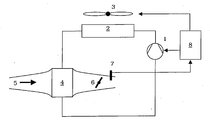
- the single figure shows schematically the components of a charge air cooling arrangement according to the present invention.
- heat is transferred from the charge air to a coolant like especially water. This is in a separate, from the engine cooling Pumped independent coolant circuit on which the charge air cooler 4, a Pump 1 and a heat exchanger 2 are connected. In the heat exchanger 2 the heat absorbed by the coolant is released into the ambient air.
- the heat exchanger 2 can additionally by a blower 3 with ambient air be blown to achieve an increased heat transfer.
- control unit 8 is with the temperature sensor 7 connected in order to obtain a signal indicating the charge air temperature from the latter. If necessary, the control unit 8 can have further sensory inputs or have data inputs (not shown) to still other operating parameters to detect the internal combustion engine.
- control unit 8 On the output side is the control unit 8 with the water pump 1 and the Blower 3 connected.
- the control unit 8 can use these outputs to perform the water pump 1 and the blower 3 vary or these Put the elements down completely. If the control unit 8 determines that the Charge air temperature is already at a desired (low) level, throttling the cooling can save electricity on the one hand and on the other Make sure that the charge air temperature is not below the desired one Level drops.
- control unit 8 can ensure that the charge air temperature optimally adapted to different operating conditions of the internal combustion engine is. This can be especially the case after starting the engine and during warming up
- the engine regulates the charge air temperature to a relatively high value to support a quick warm-up of the internal combustion engine.
- heating devices e.g. in the coolant circuit
Abstract
Description
Die Erfindung betrifft ein Verfahren zur Regelung der Temperatur der Ladeluft in einer Brennkraftmaschine mit einem Ladeluftkühler, wobei der Ladeluftkühler zusammen mit einer Kühlmittelpumpe und einem Wärmetauscher in einem Kühlmittelkreislauf angeordnet ist. Ferner betrifft die Erfindung eine Ladeluft-Kühlungsanordnung für eine Brennkraftmaschine enthaltend
- einen Ladeluftkühler, durch welchen die zu kühlende Ladeluft geleitet wird;
- einen Kühlmittelkreislauf enthaltend den Ladeluftkühler, eine Kühlmittelpumpe sowie einen Wärmetauscher;
- einen Temperatursensor, welcher im Strömungsweg der Ladeluft angeordnet ist.
- a charge air cooler through which the charge air to be cooled is passed;
- a coolant circuit containing the charge air cooler, a coolant pump and a heat exchanger;
- a temperature sensor which is arranged in the flow path of the charge air.
Zur Steigerung der Leistung von Brennkraftmaschinen ist es bekannt, die der Brennkraftmaschine zugeführte Luft ("Ladeluft") vor ihrer Mischung mit dem Kraftstoff zu verdichten. Die bei dieser Verdichtung der Ladeluft auftretende Erwärmung ist jedoch in der Regel unerwünscht, so dass die Temperatur mit Hilfe eines Ladeluftkühlers wieder auf ein gewünschtes Niveau abgesenkt wird. Der Ladeluftkühler oder Zwischenkühler ist bei bekannten Systemen in der Regel in einen Kühlwasserkreislauf eingebunden, wobei das Kühlwasser ständig mit einer elektrischen Pumpe umgepumpt wird. Ein Wärmeentzug aus dem umgepumpten Kühlwasser erfolgt in der Regel mittels eines Wärmetauschers, welcher mit Umgebungsluft gekühlt wird. Nachteilig bei diesen bekannten Verfahren ist, dass die Kühlwasserpumpe ständig in Betrieb ist, was einen entsprechenden Stromverbrauch mit sich bringt. Ferner zeigt es sich, dass die Kühlung der Ladeluft nicht für jeden Betriebszustand des Motors optimal ist.To increase the performance of internal combustion engines, it is known that the Air supplied to the internal combustion engine (“charge air”) before it is mixed with the fuel to condense. The heating that occurs during this compression of the charge air is usually undesirable, however, so the temperature with the help of a Charge air cooler is lowered again to a desired level. The intercooler or intercooler is usually in one in known systems Cooling water circuit integrated, the cooling water constantly with an electrical Pump is pumped over. A withdrawal of heat from the pumped cooling water usually takes place by means of a heat exchanger, which with ambient air is cooled. A disadvantage of these known methods is that the Cooling water pump is constantly in operation, which means a corresponding power consumption brings with it. It also shows that the cooling of the charge air is not is optimal for every operating condition of the engine.
Um die Kühlung der Ladeluft abhängig von der Temperatur der Ladeluft vornehmen zu können, ist es aus der US 5 632 256, der US 5 669 363, der WO 92/01145 und der EP 0 708 231 bekannt, die Ladeluft über einen regelbaren Bypass am Zwischenkühler vorbei und direkt in den Motor zu leiten. Nachteilig hieran ist jedoch, dass der Aufwand für die Kühlung des Ladeluftkühlers unvermindert bestehen bleibt.In order to cool the charge air depending on the temperature of the charge air to be able to, it is from US 5 632 256, US 5 669 363, WO 92/01145 and EP 0 708 231, the charge air via a controllable bypass on Intercooler over and direct into the engine. The disadvantage of this is, however, that the effort for cooling the charge air cooler remains undiminished remains.
Des weiteren ist es aus der US 5 201 285 bekannt, den Ladeluftkühler in einem Nebenstrom des Kühlmittelkreislaufes der Brennkraftmaschine anzuordnen. Dabei wird die Temperatur der Ladeluft gemessen und in Abhängigkeit hiervon mehr oder weniger Kühlmittel durch den Ladeluftkühler geleitet. Ferner wird die Geschwindigkeit eines Wärmetauschergebläses in Abhängigkeit von der Umgebungsluft des Fahrzeuges kontrolliert. Nachteilig bei diesem System ist, dass ein verhältnismäßig großer Aufwand erforderlich ist und dass die Kühlung der Brennkraftmaschine nicht unabhängig von der Ladeluftkühlung ist.Furthermore, it is known from US Pat. No. 5,201,285, the charge air cooler in one To arrange secondary flow of the coolant circuit of the internal combustion engine. there the temperature of the charge air is measured and more depending on it or less coolant passed through the charge air cooler. Furthermore, the speed a heat exchanger fan depending on the Controlled ambient air of the vehicle. The disadvantage of this system is that a relatively large effort is required and that the cooling the internal combustion engine is not independent of the charge air cooling.
Vor diesem Hintergrund war es Aufgabe der vorliegenden Erfindung, eine Vorrichtung und ein Verfahren zur Regelung der Temperatur der Ladeluft einer Brennkraftmaschine zu schaffen, welche bzw. welches eine bessere Energieausnutzung und einen besser angepassten Betrieb des Motors ermöglicht.Against this background, the object of the present invention was a device and a method for regulating the temperature of the charge air of an internal combustion engine to create which one or better energy use and enables a more adapted operation of the engine.
Diese Aufgabe wird durch ein Verfahren mit den Merkmalen des Anspruchs 1 und
eine Ladeluft-Kühlungsanordnung mit den Merkmalen des Anspruchs 5 gelöst.
Vorteilhafte Ausgestaltungen sind in den Unteransprüchen enthalten.This object is achieved by a method having the features of
Das erfindungsgemäße Verfahren dient der Regelung der Temperatur der Ladeluft in einer Brennkraftmaschine mit Ladeluftkühler, wobei der Ladeluftkühler gemeinsam mit einer Kühlmittelpumpe und einem Wärmetauscher in einem Kühlmittelkreislauf angeordnet ist. Das Verfahren ist dadurch gekennzeichnet, dass die Temperatur der Ladeluft gemessen und in Abhängigkeit hiervon die Kühlmittelpumpe des Kühlmittelkreislaufes gesteuert wird.The method according to the invention serves to regulate the temperature of the charge air in an internal combustion engine with an intercooler, the intercooler being common with a coolant pump and a heat exchanger in a coolant circuit is arranged. The process is characterized in that the The temperature of the charge air is measured and, depending on this, the coolant pump of the coolant circuit is controlled.
Anders als bei den bekannten Verfahren läuft somit die Kühlmittelpumpe des Kühlmittelkreislaufes nicht ungeregelt und ununterbrochen durch, sondern sie wird nach Bedarf in Abhängigkeit von der Temperatur der Ladeluft ein- und ausgeschaltet beziehungsweise gedrosselt. Dies spart nicht nur Energie für den Betrieb der Pumpe, sondern gewährleistet zugleich, dass sich die Temperatur der Ladeluft durchgehend in einem gewünschten und optimalen Bereich befindet.In contrast to the known methods, the coolant pump of the Coolant circuit not through uncontrolled and uninterrupted, but it will as required depending on the temperature of the charge air on and off or throttled. This not only saves energy for operation the pump, but at the same time ensures that the temperature of the charge air is consistently in a desired and optimal area.
Gemäß einer Weiterbildung des Verfahrens erfolgt die Steuerung der Kühlmittelpumpe nicht nur in Abhängigkeit von der Ladelufttemperatur, sondern auch in Abhängigkeit von weiteren Betriebsparametern der Brennkraftmaschine. Hierzu kann insbesondere die Last und/oder die Drehzahl der Brennkraftmaschine gehören. Vorzugsweise wird dabei die Kühlmittelpumpe nach einem Motorstart und/oder bei mittlerer Motorlast gedrosselt betrieben oder sogar ganz ausgeschaltet. Auf diese Weise wird erreicht, dass die Temperatur der Ladeluft gegenüber einer ungedrosselten Kühlung höhere Werte annimmt, was bei einem Motorkaltstart zu einer schnelleren Erwärmung des Motors beiträgt. Bei Teillasten wird durch eine verhältnismäßig hohe Ladelufttemperatur die Kraftstoffausnutzung verbessert. Bei hoher Last der Brennkraftmaschine oder bei hohen Umgebungstemperaturen wird dagegen die Kühlmittelpumpe vorzugsweise mit maximaler Leistung betrieben, um möglichst niedrige Ladelufttemperaturen zur Optimierung der Leistungsabgabe zu erzielen.According to a development of the method, the coolant pump is controlled not only depending on the charge air temperature, but also depending of further operating parameters of the internal combustion engine. This can in particular include the load and / or the speed of the internal combustion engine. The coolant pump is preferably switched on after an engine start and / or at medium engine load operated throttled or even completely switched off. To this It is achieved that the temperature of the charge air compared to an unthrottled Cooling takes on higher values, which results in a cold engine start contributes to faster engine warming. In the case of partial loads, it is proportionate high charge air temperature improves fuel economy. at high load of the internal combustion engine or at high ambient temperatures on the other hand, the coolant pump is preferably operated at maximum power Charge air temperatures as low as possible to optimize the power output achieve.
Weiterhin kann auch der Wärmetransfer des Wärmetauschers im Kühlmittelkreislauf in Abhängigkeit von der Temperatur der Ladeluft und gegebenenfalls in Abhängigkeit von weiteren Betriebsparametern der Brennkraftmaschine verändert werden, um hierdurch die Ladelufttemperatur zu beeinflussen. Gegenüber einem ungeregelten Betrieb hat dies wiederum den Vorteil, dass die Ladelufttemperatur durchgehend in einem optimalen Bereich gehalten werden kann. Furthermore, the heat transfer of the heat exchanger in the coolant circuit can also depending on the temperature of the charge air and possibly depending changed by further operating parameters of the internal combustion engine to influence the charge air temperature. Opposite one uncontrolled operation, this in turn has the advantage that the charge air temperature can be kept in an optimal range throughout.
Wenn dabei im Wärmetauscher eine Wärmeabgabe an die Umgebungsluft erfolgt und der Wärmetauscher zu diesem Zweck mit einem Gebläse versehen ist, wird vorzugsweise die Drehzahl beziehungsweise Leistung des Gebläses in Abhängigkeit von der Temperatur der Ladeluft und/oder von Betriebsparametern der Brennkraftmaschine geregelt. Eine hohe Drehzahl beziehungsweise Leistung des Gebläses führt zu einem höheren Wärmetransfer des Wärmetauschers und folglich zu einer Absenkung der Temperatur der Ladeluft. Ein gedrosselter Gebläsebetrieb bei einem geringeren Bedarf an Kühlleistung hat hier wiederum den Vorteil, dass Strom für den Betrieb des Gebläses eingespart werden kann.If heat is released into the ambient air in the heat exchanger and the heat exchanger is provided with a fan for this purpose preferably the speed or power of the fan depending the temperature of the charge air and / or the operating parameters of the internal combustion engine regulated. A high speed or performance of the fan leads to a higher heat transfer of the heat exchanger and consequently to lower the temperature of the charge air. A throttled fan operation with a lower cooling capacity requirement, the advantage here is that Electricity for the operation of the blower can be saved.
Die Erfindung betrifft ferner eine Ladeluft-Kühlungsanordnung für eine Brennkraftmaschine, welche die folgenden Elemente enthält: einen Ladeluftkühler, durch welchen die zu kühlende Ladeluft geleitet werden kann; einen Kühlmittelkreislauf, welcher den Ladeluftkühler, eine Kühlmittelpumpe sowie einen Wärmetauscher umfasst; und einen Temperatursensor, der im Strömungsweg der Ladeluft angeordnet ist. Die Ladeluft-Kühlungsanordnung ist gekennzeichnet durch eine Regelungseinheit, welche mit dem Temperatursensor, der Kühlmittelpumpe und gegebenenfalls dem Wärmetauscher gekoppelt und darüber hinaus derart eingerichtet ist, dass diese ein Verfahren der vorstehend erläuterten Art durchführen kann. Die Regelung ist somit insbesondere im Stande, in Abhängigkeit von der gemessenen Temperatur der Ladeluft die Kühlmittelpumpe des Kühlmittelkreislaufes zu steuern. Sofern die Regelung mit dem Wärmetauscher verbunden ist, kann diese darüber hinaus auch Einfluss auf den Wärmetransfer des Wärmetauschers nehmen.The invention further relates to a charge air cooling arrangement for an internal combustion engine, which contains the following elements: an intercooler, by which the charge air to be cooled can be directed; a coolant circuit, which includes the charge air cooler, a coolant pump and a heat exchanger includes; and a temperature sensor arranged in the flow path of the charge air is. The charge air cooling arrangement is characterized by a control unit, which with the temperature sensor, the coolant pump and possibly coupled to the heat exchanger and also set up in this way is that this can carry out a method of the type explained above. The Regulation is therefore particularly able, depending on the measured Temperature of the charge air to control the coolant pump of the coolant circuit. If the control is connected to the heat exchanger, this can be done via it also influence the heat transfer of the heat exchanger.
Vorzugsweise enthält der Wärmetauscher ein Gebläse zur zwangsweisen Zuführung von Umgebungsluft, wobei die Regelung Einfluss auf die Drehzahl und Leistung dieses Gebläses nehmen kann.The heat exchanger preferably contains a blower for forced feeding of ambient air, the regulation influencing the speed and power this blower can take.
Im Folgenden wird die Erfindung anhand der Figur beispielhaft näher erläutert.In the following, the invention is explained in more detail by way of example using the figure.
Die einzige Figur zeigt schematisch die Komponenten einer Ladeluft-Kühlungsanordnung gemäß der vorliegenden Erfindung. The single figure shows schematically the components of a charge air cooling arrangement according to the present invention.
Die für den Verbrennungsvorgang in einer Brennkraftmaschine (nicht dargestellt)
vorgesehene, vorzugsweise komprimierte Ladeluft 5 durchläuft einen Ladeluftkühler
4 ("Intercooler") in der durch den Pfeil angedeuteten Richtung, wobei die durch
die Kompression der Ladeluft entstehende Temperaturerhöhung im Ladeluftkühler
4 wieder abgebaut werden soll. An der Ausgangsseite des Ladeluftkühlers 4
befindet sich eine Drosselklappe 6 im Ladeluftstrom, mit welcher die Größe dieses
Stromes beeinflusst werden kann. Ferner befindet sich im Ladeluftstrom ein
Temperatursensor 7 zur Erfassung der Temperatur der Ladeluft.The for the combustion process in an internal combustion engine (not shown)
provided, preferably
Im Ladeluftkühler 4 erfolgt ein Wärmetransfer von der Ladeluft auf ein Kühlmittel
wie insbesondere Wasser. Dieses wird in einem separaten, von der Motorkühlung
unabhängigen Kühlmittelkreislauf umgepumpt, an dem der Ladeluftkühler 4, eine
Pumpe 1 sowie ein Wärmetauscher 2 angeschlossen sind. Im Wärmetauscher 2
wird die vom Kühlmittel aufgenommene Wärme an die Umgebungsluft abgegeben.
Der Wärmetauscher 2 kann zusätzlich von einem Gebläse 3 mit Umgebungsluft
angeblasen werden, um einen gesteigerten Wärmetransfer zu erzielen.In the
Während bei bekannten Ladeluft-Kühlungsanordnungen die Wasserpumpe 1 auf
konstantem Niveau betrieben wird und somit durchgehend eine maximale Kühlung
der Ladeluft 5 stattfindet, wird erfindungsgemäß der Einsatz einer Regelungseinheit
8 vorgeschlagen. Die Regelungseinheit 8 ist mit dem Temperatursensor 7
verbunden, um von diesem ein die Ladelufttemperatur anzeigendes Signal zu erhalten.
Gegebenenfalls kann die Regelungseinheit 8 weitere sensorische Eingänge
oder Dateneingänge aufweisen (nicht dargestellt), um noch andere Betriebsparameter
der Brennkraftmaschine zu erfassen.While in known charge air cooling arrangements, the
Ausgangsseitig ist die Regelungseinheit 8 mit der Wasserpumpe 1 sowie dem
Gebläse 3 verbunden. Über diese Ausgänge kann die Regelungseinheit 8 die Leistung
der Wasserpumpe 1 und des Gebläses 3 variieren beziehungsweise diese
Elemente ganz abstellen. Wenn die Regelungseinheit 8 etwa feststellt, dass die
Ladelufttemperatur sich bereits auf einem gewünschten (niedrigen) Niveau befindet,
kann sie durch eine Drosselung der Kühlung einerseits Strom sparen und andererseits
sicherstellen, dass die Ladelufttemperatur nicht unter das gewünschte
Niveau absinkt.On the output side is the
Weiterhin kann die Regelungseinheit 8 dafür sorgen, dass die Ladelufttemperatur
verschiedenen Betriebsbedingungen der Brennkraftmaschine optimal angepasst
ist. So kann insbesondere nach einem Motorstart und während des Aufwärmens
des Motors die Ladelufttemperatur auf einen verhältnismäßig hohen Wert geregelt
werden, um ein schnelles Aufwärmen der Brennkraftmaschine zu unterstützen.
Gegebenenfalls können zu diesem Zweck auch Heizeinrichtungen (z.B. im Kühlmittelkreislauf)
vorgesehen werden, so dass im Ladeluftkühler 4 entgegen dem
üblichen Betrieb eine Erhöhung der Temperatur der Ladeluft 5 stattfinden kann.Furthermore, the
Bei Teillast der Brennkraftmaschine ist es ebenfalls von Vorteil, im Hinblick auf eine verhältnismäßig hohe Ladelufttemperatur zu regeln, um die Kraftstoffausnutzung zu verbessern.At partial load of the internal combustion engine, it is also advantageous with regard to regulate a relatively high charge air temperature to fuel economy to improve.
Bei hoher Last oder bei hohen Umgebungstemperaturen ist es dagegen wünschenswert, die Ladelufttemperatur auf ein niedriges Niveau herunter zu regeln, um die Leistungsabgabe zu optimieren.In contrast, at high loads or at high ambient temperatures, it is desirable regulating the charge air temperature down to a low level, to optimize the power output.
Mit der vorgeschlagenen Ladeluft-Kühlungsanordnung wird somit sowohl eine
Stromersparnis beim Betrieb der Wasserpumpe 1 beziehungsweise des Gebläses
3 als auch eine bessere Anpassung der Ladelufttemperatur an den Motorbetriebszustand
erzielt.With the proposed charge air cooling arrangement, both a
Saving electricity when operating the
Claims (6)
dadurch gekennzeichnet, dass die Temperatur der Ladeluft (5) gemessen und in Abhängigkeit hiervon die Kühlmittelpumpe (1) des Kühlmittelkreislaufes gesteuert wird.Method for regulating the temperature of the charge air (5) in an internal combustion engine with a charge air cooler (4), the charge air cooler being arranged in a coolant circuit together with a coolant pump (1) and a heat exchanger (2, 3),
characterized in that the temperature of the charge air (5) is measured and the coolant pump (1) of the coolant circuit is controlled as a function thereof.
dadurch gekennzeichnet, dass die Steuerung der Kühlmittelpumpe (1) in Abhängigkeit von weiteren Betriebsparametern der Brennkraftmaschine erfolgt, wobei vorzugsweise die Kühlmittelpumpe (1) nach einem Motorstart und/oder bei mittlerer Motorlast ausgeschaltet oder gedrosselt wird.Method according to claim 1,
characterized in that the coolant pump (1) is controlled as a function of further operating parameters of the internal combustion engine, the coolant pump (1) preferably being switched off or throttled after an engine start and / or with an average engine load.
dadurch gekennzeichnet, dass der Wärmetransfer des Wärmetauschers (2, 3) in Abhängigkeit von der Temperatur der Ladeluft (5) und gegebenenfalls von weiteren Betriebsparametern der Brennkraftmaschine verändert wird.Method according to one of claims 1 or 2,
characterized in that the heat transfer of the heat exchanger (2, 3) is changed as a function of the temperature of the charge air (5) and possibly other operating parameters of the internal combustion engine.
dadurch gekennzeichnet, dass das Gebläse (3) eines luftgekühlten Wärmetauschers (2, 3) geregelt wird. Method according to claim 3,
characterized in that the fan (3) of an air-cooled heat exchanger (2, 3) is regulated.
dadurch gekennzeichnet, dass der Wärmetauscher (2) ein Gebläse (3) zur Kühlung mit Umgebungsluft umfasst.Charge air cooling arrangement according to claim 5,
characterized in that the heat exchanger (2) comprises a blower (3) for cooling with ambient air.
Priority Applications (2)
| Application Number | Priority Date | Filing Date | Title |
|---|---|---|---|
| EP01115872A EP1270895A1 (en) | 2001-06-29 | 2001-06-29 | Charge air temperature control for engines with turbo intercooler |
| US10/185,482 US20030056772A1 (en) | 2001-06-29 | 2002-07-01 | Method and system for regulating the air charge temperature in engines having an intercooler |
Applications Claiming Priority (1)
| Application Number | Priority Date | Filing Date | Title |
|---|---|---|---|
| EP01115872A EP1270895A1 (en) | 2001-06-29 | 2001-06-29 | Charge air temperature control for engines with turbo intercooler |
Publications (1)
| Publication Number | Publication Date |
|---|---|
| EP1270895A1 true EP1270895A1 (en) | 2003-01-02 |
Family
ID=8177890
Family Applications (1)
| Application Number | Title | Priority Date | Filing Date |
|---|---|---|---|
| EP01115872A Withdrawn EP1270895A1 (en) | 2001-06-29 | 2001-06-29 | Charge air temperature control for engines with turbo intercooler |
Country Status (2)
| Country | Link |
|---|---|
| US (1) | US20030056772A1 (en) |
| EP (1) | EP1270895A1 (en) |
Cited By (2)
| Publication number | Priority date | Publication date | Assignee | Title |
|---|---|---|---|---|
| CN108138670A (en) * | 2015-10-15 | 2018-06-08 | 大众汽车有限公司 | The control of the pump of conveying cooling agent in inlet gas cooling cycle |
| DE112015002826B4 (en) | 2014-06-16 | 2020-07-30 | Denso Corporation | Intake air cooler |
Families Citing this family (11)
| Publication number | Priority date | Publication date | Assignee | Title |
|---|---|---|---|---|
| JP3972863B2 (en) * | 2003-05-26 | 2007-09-05 | 株式会社デンソー | Vehicle cooling system |
| US7454896B2 (en) * | 2005-02-23 | 2008-11-25 | Emp Advanced Development, Llc | Thermal management system for a vehicle |
| US7669417B2 (en) * | 2006-01-30 | 2010-03-02 | Titan Research And Innovations Pty Ltd | Engine after-cooling system |
| SE533416C2 (en) * | 2008-09-25 | 2010-09-21 | Scania Cv Ab | Cooling arrangements that reduce the risk of ice formation in the cooler of a supercharged internal combustion engine |
| RU2613475C2 (en) * | 2011-09-03 | 2017-03-16 | Роберт Бош Гмбх | Supplied to internal combustion engine supercharging air cooler fan drive controlling device and method |
| JP2013256936A (en) * | 2012-05-16 | 2013-12-26 | Denso Corp | Exhaust recirculating device |
| JP6364895B2 (en) * | 2014-04-02 | 2018-08-01 | 株式会社デンソー | EGR system for internal combustion engine |
| US9551275B2 (en) * | 2014-08-07 | 2017-01-24 | Caterpillar Inc. | Cooling system having pulsed fan control |
| US9709065B2 (en) | 2014-11-06 | 2017-07-18 | Ford Global Technologies, Llc | System and method for a turbocharger driven coolant pump |
| US10557406B2 (en) * | 2017-05-15 | 2020-02-11 | GM Global Technology Operations LLC | System and method for regulating coolant flow through a charge air cooler of a vehicle |
| EP3675145B1 (en) * | 2018-12-27 | 2021-10-06 | ABB Power Grids Switzerland AG | Static electrical device assembly comprising heat exchanger system |
Citations (10)
| Publication number | Priority date | Publication date | Assignee | Title |
|---|---|---|---|---|
| JPS58150022A (en) * | 1982-03-02 | 1983-09-06 | Toyota Motor Corp | Intake air cooling device in internal-combustion engine |
| JPS60212616A (en) * | 1984-04-09 | 1985-10-24 | Hanshin Electric Co Ltd | Inter-cooler controlling device in turbo-supercharger |
| US4632178A (en) * | 1983-10-26 | 1986-12-30 | Nissan Motor Co., Ltd. | Intercooler for supercharged internal combustion engine |
| JPH01177406A (en) * | 1987-12-28 | 1989-07-13 | Honda Motor Co Ltd | Cooling control method for turbocharger and intercooler |
| WO1992001145A1 (en) | 1990-07-03 | 1992-01-23 | Allied-Signal Inc. | Engine intake temperature control system |
| US5201285A (en) | 1991-10-18 | 1993-04-13 | Touchstone, Inc. | Controlled cooling system for a turbocharged internal combustion engine |
| EP0708231A1 (en) | 1994-10-21 | 1996-04-24 | Valeo Thermique Moteur | Control device for the cooling of the charge air for heat engine |
| US5632256A (en) | 1995-03-07 | 1997-05-27 | Mercedes-Benz Ag | Internal combustion engine with an exhaust gas turbocharger |
| US5669363A (en) | 1993-12-02 | 1997-09-23 | Amot Controls Limited | Turbocharger intercooler control means |
| JPH11294164A (en) * | 1998-04-16 | 1999-10-26 | Nissan Motor Co Ltd | Control device for cooling fan |
Family Cites Families (3)
| Publication number | Priority date | Publication date | Assignee | Title |
|---|---|---|---|---|
| DE3483349D1 (en) * | 1983-10-25 | 1990-11-08 | Nissan Motor | COOLING DEVICE FOR A MOTOR VEHICLE. |
| US6367256B1 (en) * | 2001-03-26 | 2002-04-09 | Detroit Diesel Corporation | Exhaust gas recirculation with condensation control |
| US6561169B2 (en) * | 2001-07-23 | 2003-05-13 | Ford Motor Company | Charge air management system for automotive engine |
-
2001
- 2001-06-29 EP EP01115872A patent/EP1270895A1/en not_active Withdrawn
-
2002
- 2002-07-01 US US10/185,482 patent/US20030056772A1/en not_active Abandoned
Patent Citations (10)
| Publication number | Priority date | Publication date | Assignee | Title |
|---|---|---|---|---|
| JPS58150022A (en) * | 1982-03-02 | 1983-09-06 | Toyota Motor Corp | Intake air cooling device in internal-combustion engine |
| US4632178A (en) * | 1983-10-26 | 1986-12-30 | Nissan Motor Co., Ltd. | Intercooler for supercharged internal combustion engine |
| JPS60212616A (en) * | 1984-04-09 | 1985-10-24 | Hanshin Electric Co Ltd | Inter-cooler controlling device in turbo-supercharger |
| JPH01177406A (en) * | 1987-12-28 | 1989-07-13 | Honda Motor Co Ltd | Cooling control method for turbocharger and intercooler |
| WO1992001145A1 (en) | 1990-07-03 | 1992-01-23 | Allied-Signal Inc. | Engine intake temperature control system |
| US5201285A (en) | 1991-10-18 | 1993-04-13 | Touchstone, Inc. | Controlled cooling system for a turbocharged internal combustion engine |
| US5669363A (en) | 1993-12-02 | 1997-09-23 | Amot Controls Limited | Turbocharger intercooler control means |
| EP0708231A1 (en) | 1994-10-21 | 1996-04-24 | Valeo Thermique Moteur | Control device for the cooling of the charge air for heat engine |
| US5632256A (en) | 1995-03-07 | 1997-05-27 | Mercedes-Benz Ag | Internal combustion engine with an exhaust gas turbocharger |
| JPH11294164A (en) * | 1998-04-16 | 1999-10-26 | Nissan Motor Co Ltd | Control device for cooling fan |
Non-Patent Citations (4)
| Title |
|---|
| PATENT ABSTRACTS OF JAPAN vol. 007, no. 271 (M - 260) 3 December 1983 (1983-12-03) * |
| PATENT ABSTRACTS OF JAPAN vol. 010, no. 066 (M - 461) 15 March 1986 (1986-03-15) * |
| PATENT ABSTRACTS OF JAPAN vol. 013, no. 455 (M - 879) 13 October 1989 (1989-10-13) * |
| PATENT ABSTRACTS OF JAPAN vol. 2000, no. 01 31 January 2000 (2000-01-31) * |
Cited By (3)
| Publication number | Priority date | Publication date | Assignee | Title |
|---|---|---|---|---|
| DE112015002826B4 (en) | 2014-06-16 | 2020-07-30 | Denso Corporation | Intake air cooler |
| CN108138670A (en) * | 2015-10-15 | 2018-06-08 | 大众汽车有限公司 | The control of the pump of conveying cooling agent in inlet gas cooling cycle |
| CN108138670B (en) * | 2015-10-15 | 2021-04-20 | 大众汽车有限公司 | Control of a pump delivering coolant in a charge air cooling cycle |
Also Published As
| Publication number | Publication date |
|---|---|
| US20030056772A1 (en) | 2003-03-27 |
Similar Documents
| Publication | Publication Date | Title |
|---|---|---|
| EP0638712B1 (en) | Coolant circuit | |
| DE69834891T2 (en) | Cooling system for the internal combustion engine of a locomotive | |
| DE102011108648B4 (en) | Method and system for thermal regulation of a battery pack | |
| EP1270895A1 (en) | Charge air temperature control for engines with turbo intercooler | |
| EP2213859B1 (en) | Method for regulating a charge air cooler | |
| DE102015216420B4 (en) | Cooling arrangement for charge air cooling | |
| DE102015222232B4 (en) | COOLING CONTROL / CONTROL SYSTEM FOR A COMBUSTION ENGINE | |
| DE102008028290A1 (en) | Means for cooling a coolant, a circuit for charging an internal combustion engine and method for cooling an intended for charging an internal combustion engine substantially gaseous charging fluid | |
| DE3812267C2 (en) | Speed control device for a hydraulically operated cooling fan of an internal combustion engine | |
| WO2006066713A1 (en) | System and method for regulating the temperature of the motor oil in an internal combustion engine of a motor vehicle | |
| DE102019105893B4 (en) | Thermal management system for a vehicle drive system | |
| EP1454039A1 (en) | Method for the temperature regulation of an engine | |
| DE102004021551A1 (en) | Cooling system especially for vehicle has a main cooling circuit and with several parallel circuits with different performance to cool accessories | |
| DE102017130710B4 (en) | engine system | |
| EP0931208B1 (en) | Method and control of regulation of vehicle cooling circuit by means of a thermally regulated water pump | |
| EP1308610B1 (en) | Method and device for controlling a cooling system of an internal combustion engine | |
| EP3760848B1 (en) | Arrangement and method for controlling the temperature of an internal combustion engine and electric drive components of a hybrid vehicle | |
| EP0931209B1 (en) | Drive unit with a thermally regulated water pump | |
| DE10319333B4 (en) | System and method for influencing the intake gas temperature in the combustion chamber of an internal combustion engine | |
| DE10319330B4 (en) | System and method for influencing the intake gas temperature in the combustion chamber of an internal combustion engine | |
| DE202013100932U1 (en) | Intercooler system with integrated heating device | |
| EP1523612B1 (en) | Method and device for regulating the temperature of a coolant in an internal combustion engine | |
| EP0508068A1 (en) | Supercharged temperature control device for an internal combustion engine in dependence on the temperature of the dew point of the charged air | |
| DE10158917B4 (en) | Control unit for a radiator fan | |
| DE102009056575B4 (en) | Method and device for determining a modeled temperature value in an internal combustion engine and method for plausibility of a temperature sensor |
Legal Events
| Date | Code | Title | Description |
|---|---|---|---|
| PUAI | Public reference made under article 153(3) epc to a published international application that has entered the european phase |
Free format text: ORIGINAL CODE: 0009012 |
|
| AK | Designated contracting states |
Kind code of ref document: A1 Designated state(s): AT BE CH CY DE DK ES FI FR GB GR IE IT LI LU MC NL PT SE TR |
|
| AX | Request for extension of the european patent |
Free format text: AL;LT;LV;MK;RO;SI |
|
| STAA | Information on the status of an ep patent application or granted ep patent |
Free format text: STATUS: THE APPLICATION HAS BEEN WITHDRAWN |
|
| 18W | Application withdrawn |
Effective date: 20030227 |