EP1270766A2 - Electrodeposition coating film thickness calculating method and electrodeposition coating film thickness simulation apparatus - Google Patents
Electrodeposition coating film thickness calculating method and electrodeposition coating film thickness simulation apparatus Download PDFInfo
- Publication number
- EP1270766A2 EP1270766A2 EP02009129A EP02009129A EP1270766A2 EP 1270766 A2 EP1270766 A2 EP 1270766A2 EP 02009129 A EP02009129 A EP 02009129A EP 02009129 A EP02009129 A EP 02009129A EP 1270766 A2 EP1270766 A2 EP 1270766A2
- Authority
- EP
- European Patent Office
- Prior art keywords
- electric variable
- deposition
- electrodeposition coating
- coating
- calculating
- Prior art date
- Legal status (The legal status is an assumption and is not a legal conclusion. Google has not performed a legal analysis and makes no representation as to the accuracy of the status listed.)
- Withdrawn
Links
- 238000000576 coating method Methods 0.000 title claims abstract description 126
- 239000011248 coating agent Substances 0.000 title claims abstract description 125
- 238000004070 electrodeposition Methods 0.000 title claims abstract description 73
- 238000000034 method Methods 0.000 title claims abstract description 28
- 238000004088 simulation Methods 0.000 title claims abstract description 7
- 238000000151 deposition Methods 0.000 claims abstract description 59
- 230000008021 deposition Effects 0.000 claims abstract description 59
- 238000009826 distribution Methods 0.000 claims abstract description 21
- 230000001186 cumulative effect Effects 0.000 claims abstract description 14
- 239000002659 electrodeposit Substances 0.000 claims abstract description 12
- 230000005611 electricity Effects 0.000 claims description 15
- 239000012530 fluid Substances 0.000 claims description 11
- 238000000611 regression analysis Methods 0.000 claims description 7
- 230000008859 change Effects 0.000 abstract description 6
- 230000005684 electric field Effects 0.000 abstract 1
- 239000003973 paint Substances 0.000 description 19
- 238000004458 analytical method Methods 0.000 description 15
- 238000010586 diagram Methods 0.000 description 9
- 230000014509 gene expression Effects 0.000 description 9
- 238000004364 calculation method Methods 0.000 description 8
- 238000002474 experimental method Methods 0.000 description 7
- 239000002245 particle Substances 0.000 description 7
- 230000008569 process Effects 0.000 description 6
- 230000006870 function Effects 0.000 description 5
- 230000015572 biosynthetic process Effects 0.000 description 4
- 238000009792 diffusion process Methods 0.000 description 4
- 238000012360 testing method Methods 0.000 description 4
- 150000001768 cations Chemical class 0.000 description 2
- 239000006185 dispersion Substances 0.000 description 2
- 238000005259 measurement Methods 0.000 description 2
- 230000007246 mechanism Effects 0.000 description 2
- XLYOFNOQVPJJNP-UHFFFAOYSA-N water Substances O XLYOFNOQVPJJNP-UHFFFAOYSA-N 0.000 description 2
- 230000000052 comparative effect Effects 0.000 description 1
- 239000004020 conductor Substances 0.000 description 1
- 238000010276 construction Methods 0.000 description 1
- 230000007423 decrease Effects 0.000 description 1
- 230000003111 delayed effect Effects 0.000 description 1
- 238000001962 electrophoresis Methods 0.000 description 1
- XLYOFNOQVPJJNP-ZSJDYOACSA-N heavy water Substances [2H]O[2H] XLYOFNOQVPJJNP-ZSJDYOACSA-N 0.000 description 1
- 239000011810 insulating material Substances 0.000 description 1
- 150000002500 ions Chemical class 0.000 description 1
- 239000007788 liquid Substances 0.000 description 1
- 238000004519 manufacturing process Methods 0.000 description 1
- 239000000463 material Substances 0.000 description 1
- 239000002184 metal Substances 0.000 description 1
- 239000007769 metal material Substances 0.000 description 1
- 238000013508 migration Methods 0.000 description 1
- 230000005012 migration Effects 0.000 description 1
- 238000012986 modification Methods 0.000 description 1
- 230000004048 modification Effects 0.000 description 1
- 230000002093 peripheral effect Effects 0.000 description 1
- 238000007747 plating Methods 0.000 description 1
- 238000012545 processing Methods 0.000 description 1
- 239000012779 reinforcing material Substances 0.000 description 1
- 239000007787 solid Substances 0.000 description 1
- 238000003756 stirring Methods 0.000 description 1
Images


Classifications
-
- G—PHYSICS
- G01—MEASURING; TESTING
- G01B—MEASURING LENGTH, THICKNESS OR SIMILAR LINEAR DIMENSIONS; MEASURING ANGLES; MEASURING AREAS; MEASURING IRREGULARITIES OF SURFACES OR CONTOURS
- G01B21/00—Measuring arrangements or details thereof, where the measuring technique is not covered by the other groups of this subclass, unspecified or not relevant
- G01B21/02—Measuring arrangements or details thereof, where the measuring technique is not covered by the other groups of this subclass, unspecified or not relevant for measuring length, width, or thickness
- G01B21/08—Measuring arrangements or details thereof, where the measuring technique is not covered by the other groups of this subclass, unspecified or not relevant for measuring length, width, or thickness for measuring thickness
-
- C—CHEMISTRY; METALLURGY
- C25—ELECTROLYTIC OR ELECTROPHORETIC PROCESSES; APPARATUS THEREFOR
- C25D—PROCESSES FOR THE ELECTROLYTIC OR ELECTROPHORETIC PRODUCTION OF COATINGS; ELECTROFORMING; APPARATUS THEREFOR
- C25D13/00—Electrophoretic coating characterised by the process
- C25D13/12—Electrophoretic coating characterised by the process characterised by the article coated
- C25D13/14—Tubes; Rings; Hollow bodies
-
- C—CHEMISTRY; METALLURGY
- C25—ELECTROLYTIC OR ELECTROPHORETIC PROCESSES; APPARATUS THEREFOR
- C25D—PROCESSES FOR THE ELECTROLYTIC OR ELECTROPHORETIC PRODUCTION OF COATINGS; ELECTROFORMING; APPARATUS THEREFOR
- C25D13/00—Electrophoretic coating characterised by the process
- C25D13/22—Servicing or operating apparatus or multistep processes
-
- C—CHEMISTRY; METALLURGY
- C25—ELECTROLYTIC OR ELECTROPHORETIC PROCESSES; APPARATUS THEREFOR
- C25D—PROCESSES FOR THE ELECTROLYTIC OR ELECTROPHORETIC PRODUCTION OF COATINGS; ELECTROFORMING; APPARATUS THEREFOR
- C25D21/00—Processes for servicing or operating cells for electrolytic coating
- C25D21/12—Process control or regulation
Definitions
- the present invention relates to an electrodeposition coating film thickness calculating method for calculating the thickness of an electrodeposition coating film and an electrodeposition coating film thickness simulation apparatus.
- Electrodeposition coating is carried out in a manner such that a to-be-coated object such as the body of an automobile, an anode, and a cathode are located in an electrolytic cell that is filled with an electrodeposition coating fluid, and a film is formed on the surface of the to-be-coated object by electrophoresis.
- the film is first formed on the surface of an outside plate portion of the to-be-coated object that is subject to high voltage.
- the electrodeposition coating enjoys good throwing power such that paint particles gradually adhere to the inner part of the to-be-coated object that bears no film as the film resistance of the outside plate portion increases.
- the electrodeposition coating is used as prime-coating for the underside of the body of an automobile.
- a film cannot be easily formed inside a pouchy structure of the car body. It is hard, in particular, to form a film inside a frame member of the car body, such as a side frame portion that is expected to store a reinforcing material for safety, as well as the pouchy structure.
- film formation requires thickness control.
- an actual production line is used to apply electrodeposition coating to an actually manufactured car body, in order to confirm satisfactory film formation. Thereafter, various parts of the car body are cut, and the thickness of a film on each inside part is measured to be checked for adequacy.
- the object of the present invention is to provide an electrodeposition coating film thickness calculating method capable of calculating the respective thicknesses of films electrodeposited on various parts of a to-be-coated object with high accuracy by using data on an analytic model that replaces the to-be-coated object without using the actual to-be-coated object and an electrodeposition coating film thickness simulation apparatus.
- FIG. 1 shows a system used to calculate the thickness of an electrodeposition coating film.
- numeral 1 denotes a personal computer (hereinafter referred to as PC).
- the body of the PC 1 is mounted with a CPU 2 and a memory 3. Further, the PC 1 is connected with a keyboard 4, display unit 5, and FDD (floppy disc drive) 6.
- PC personal computer
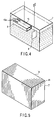
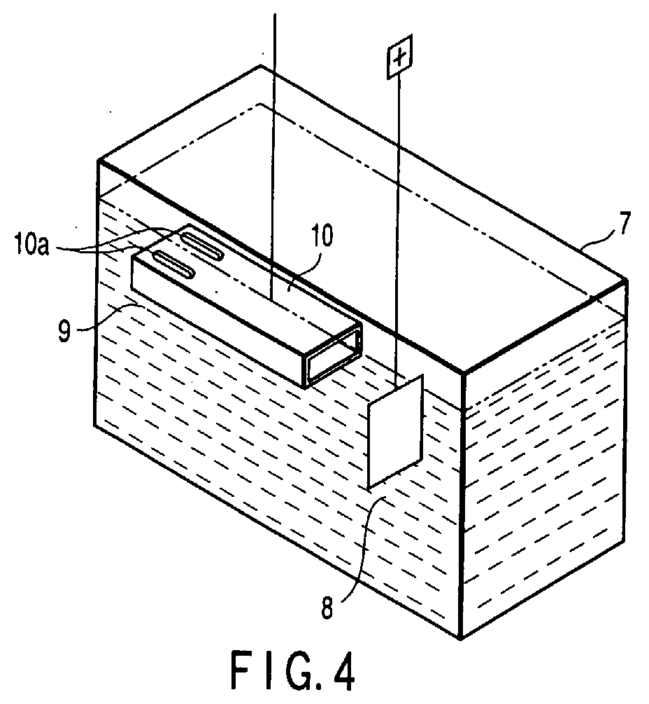
- the memory 3 is stored with a finite element method program that is needed in preparing a meshed finite element model, for example. Based on this finite element method program, a finite element model is prepared that replaces an electrolytic cell 7 filled with an electrodeposition coating fluid used in an actual electrodeposition coating process, for example, shown in FIG. 4, an anode 8 and a cathode 9 that are located in the fluid in the electrolytic cell 7, and a to-be-coated object, such as a front side member portion 10 (e.g., a portion in the form of a flat bottomed tube having small holes 10a in a part of its peripheral wall) of the body of an automobile, located in the fluid so as to conduct to the cathode 9.
- a front side member portion 10 e.g., a portion in the form of a flat bottomed tube having small holes 10a in a part of its peripheral wall
- the memory 3 is stored with:
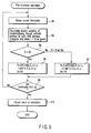
- FIGS. 2 and 3 show processes for the film thickness calculation made by means of the functions described above.
- Step S1 an analytic model of the environment of electrodeposition coating for the side member portion 10 (to-be-coated object) in Step S1.
- the finite element method is used for this process.
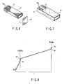
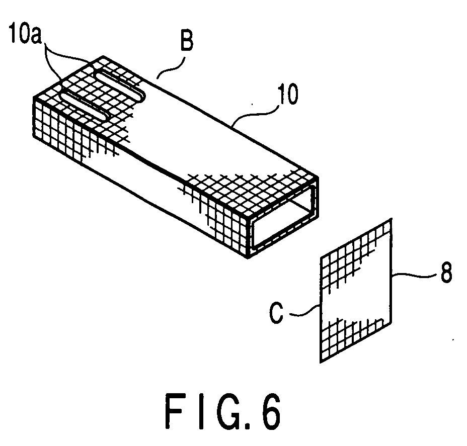
- the PC 1 is operated to prepare meshed analytic models (finite element models) of finite elements, including an analytic model A of the electrolytic cell 7, analytic model B of the side member portion 10, and analytic model C of the anode 8, according to data on the individual members and components, as shown in FIGS. 5 and 6.
- These analytic models A to C are based on the respective shapes of the electrolytic cell 7 that is filled with the actual electrodeposition coating fluid, anode 8, cathode 9, and side member portion 10 that conducts to the cathode 9, as shown in FIG. 4.
- the PC 1 is operated to supply current between the anode 8 and the cathode 9, as in the case of the actual electrodeposition coating, thereby simulating the time-based potential distribution in the electrolytic cell 7 that is the distribution obtained when the side member portion 10 is subjected to electrodeposition coating.
- the program advances to Step S3, a process for calculating the film thickness for each element A1.
- RNH 3 + represents paint particles. If current is supplied to a cation-based paint in the manner based on equation (3), water is electrolyzed on the cathode surface to generate OH- ions. When its concentration then attains a certain level, OH- ions react with the paint particles dispersed in a solution and generates water as indicated by equation (4). The paint particles discharged by this reaction are extracted as a film on the electrode surface. Some of the generated OH- ions disappear with time from a region near the electrode under the influence of diffusion and migration.
- FIG. 8 shows the one-dimensional distribution of the potential ⁇ between the cathode and the anode.
- Vco is a potential on a boundary surface on which the film and the cathode are in contact with each other
- Vc is a potential on a boundary surface on which the film and the paint are in contact with each other.
- a current density i can be obtained from equation (6) if the potential ⁇ is settled.
- ⁇ of equation (6) is conductivity.
- the relation between the quantity of electricity and the weight of film deposit must be settled experimentally. Only if this relation can be settled, the electrodeposition coating film thickness distribution can be determined in the same manner as in the analysis of the deposit thickness distribution.
- OH - ions acts as a positive charge, and a film is separated out on the surface of the to-be-coated object or the side member portion 10. If its electrical resistance increases as the film is separated out in this manner, the paint particles are separated out in unfilmed (inside) regions (throwing power phenomenon).
- the film thickness was calculated according to a well-known computational expression for deposit thickness.
- Ic I - I d
- an attempt was made to calculate the electrodeposition coating film thickness is by properly using two computational expressions (1) and (2) that include Ic.
- Step S4 of the flowchart of FIG. 3 the distribution of the currents that flow through the respective surfaces of the various parts of the finite element model of the side member portion 10 according to a potential in the electrolytic cell is obtained during simulating time-based change of potential in the electrolytic cell of the finite element model.
- Step S5 the electric variables of the currents that flow through the respective surfaces of the elements of the model are obtained and accumulated according to the distribution of the currents.
- the electric variables are integrated when I > I d is given, and are not when I ⁇ I d is given.
- Step S6 whether or not the cumulative electric variable is higher than the deposition starting electric variable Q 0 is determined.
- Step S20 parameters C.E., ⁇ t, ⁇ , K F that fulfill the computational expression for the film thickness are externally inputted by means of the keyboard 4, for example. More specifically, values that match an electrodeposition coating environment are inputted.
- the electrodeposition coating equivalent K F , diffusively consumed current density I d , and deposition starting electric variable Q 0 are settled in an experiment using a testing set, e.g., a constant-voltage coating test on flat plates.
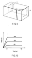
- FIG. 10 shows a time chart for the coating voltages.
- the temperatures and stirring conditions are adjusted to the electrodeposition coating environment to which the analysis is applied.
- the current, quantity of electricity, and weight of deposit are measured for voltages of 50, 150, and 250 V and coating times of 60, 120, and 180 sec.
- the 180 sec is the coating time of the side member portion 10 in the actual electrodeposition coating.
- TABLE 1 shows measurement data on the quantity of electricity and the weight of deposit in terms of values per unit area.
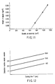
- the regression analysis is applied to the quantity of electricity and the weight of deposit for the coating voltages of 50, 150, and 250 V and the coating times of 60, 120, and 180 sec.
- the graph of FIG. 11 shows the result of application of the regression analysis.
- the graph indicates that the weight of film deposit is substantially proportional to the quantity of electricity.
- the coefficient of proportion for this case represents the weight of film deposit per 1 C, which will be referred to as electrodeposition coating equivalent K F .
- the point of intersection of the X-axis and the regression line of the graph represents an electric variable that is not related to the film deposition for 180 sec of quantity of electricity.
- the electric variable that is not associated with the deposition will be referred to as the deposition invalid electric variable for the coating time of 180 sec.
- the film deposition electric variable of TABLE 2 was obtained by dividing the weight of deposit for each coating time by a previously settled electrodeposition coating equivalent K F .
- the deposition reactive electric variable of TABLE 1 is a difference between the quantity of electricity and the film deposition electric variable for each coating time.
- the regression analysis is applied to the deposition invalid electric variable and the coating time for each of the coating voltages shown in TABLE 1 (FIG. 12).
- the increase of the deposition invalid electric variable per unit time, a coefficient of proportion will be referred to as the diffusively consumed current density.
- a Y-section value for regression analysis will be referred to as the deposition starting electric variable.
- TABLE 1 shows the diffusively consumed current density and the deposition starting electric variable for each coating voltage obtained in this manner.
- the diffusively consumed current densities for the individual coating voltages are subject to some dispersion, which is within about ⁇ 5% of the average, 2.42, shown in TABLE 3.
- This average diffusively consumed current density was settled as a diffusively consumed current density I d of a computational expression for film thickness.
- the diffusively consumed electric variable for the. coating time of 180 sec was obtained from this diffusively consumed current density I d , and the difference between this value and the deposition invalid electric variable for the coating time of 180 sec was settled as the deposition starting electric variable Q 0 of a parameter of the computational expression for film thickness for this paint (TABLE 3).
- the electrodeposition coating time at which a result of analysis want to be examined is settled.
- TABLE 2 shows processes for obtaining the conductivity of the films.
- the currents in this table are currents for the individual voltages and individual conduction times.
- the film thickness was calculated from the weight of deposit of TABLE 1 with the film density of the film generated from the electrodeposit paint using in this experiment using 1,400 kg/m 3 .
- a film voltage which is a voltage applied to the film, has a value that is obtained by subtracting a potential drop for the paint portion from the coating voltage.
- the potential drop of the paint portion was obtained as the product of the current value with the resistance of the paint portion adjusted to 53.6 ⁇ (sectional area: 100 ⁇ 160 mm, length: 150 mm, conductivity of the electrodeposit paint: 0.175 S/m).
- the respective conductivities of the films obtained in this manner were subject to a dispersion of about ⁇ 10% of the average of all the values at the maximum. This analysis used the average of all the values obtained as the conductivities K of the films.
- the cell used in. the experiment was modeled and meshed in tetrahedral elements.
- the elements include metal (cathode), film, overvoltage, paint, and anode.
- the cathode is formed of solid elements such that it is as thick as a metal material.
- a film with zero thickness and overvoltage elements are located on the outside of the cathode.
- the analytic model has 5,710 nodes and 19,838 elements. TABLE 3 shows analytic parameters. Calculation was repeated 84 times at varied intervals of 0.5, 1, 2, 3, 5, 10 and 20 sec and for the coating time of 180 sec.
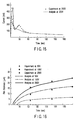
- FIGS. 13 to 15 are graphs showing comparative results of experiments and analyses on changes of all currents with time.
- FIG. 16 is a graph comparatively showing changes of film thickness with time. With all currents compared, initial peak current values for three voltages agree well with one another, and the times for the current peaks are substantially coincident, although the timing for the analyses is somewhat delayed. While there are considerable deviations after the passage of 30 sec for the voltage of 250 V, the current values for the three voltages finally agree well. Although the results of the experiments and the analyses for the film thickness distribution are subject to some differences after the passage of 60 sec, they agree well in 180 sec.
- the initial deposition coefficient ⁇ has no substantial influence on the film thickness as the result of the analysis, it is set at a value such that overshooting of current in the process of calculation and the aforementioned fluctuation of the calculated values can be prevented effectively, and is inputted from the keyboard 4 shown in S20.
- the film thickness for each element of the analytic model of the side member portion 10 is calculated with the passage of the coating time as the processes for film thickness calculation using the settled parameters advances.
- the results of the film thickness calculation (Step S10) for these individual parts are delivered to the screen of the display unit 5 (Step S11) with a film thickness distribution such that a difference in thickness is indicated by a difference in color, as shown in FIG. 7.
- the thicknesses of films electrodeposited on various parts of the to-be-coated object can be calculated with high accuracy by only executing data processing of the analytic model that replaces the to-be-coated object without using the actual to-be-coated object that is complicated and expensive. If the throwing power is insufficient, the formation of films with satisfactory thicknesses can be confirmed by only modifying data on the analytic model to change the current flow and the respective shapes of the individual parts. Thus, the film thickness can be easily controlled at low cost. Since the electric variables of the currents that flow through the surfaces of the to-be-coated object are accumulated only when the diffusively consumed current density is exceeded, in particular, the film thickness can be calculated with high accuracy.
- a program for carrying out the electrodeposition coating film thickness calculating method described in connection with the foregoing embodiment may be stored in a flexible disc.
- the program is set in an FDD 6 so that it can be downloaded.
Landscapes
- Chemical & Material Sciences (AREA)
- Engineering & Computer Science (AREA)
- Organic Chemistry (AREA)
- Electrochemistry (AREA)
- Materials Engineering (AREA)
- Metallurgy (AREA)
- Chemical Kinetics & Catalysis (AREA)
- Physics & Mathematics (AREA)
- General Physics & Mathematics (AREA)
- Automation & Control Theory (AREA)
- Paints Or Removers (AREA)
- Length Measuring Devices With Unspecified Measuring Means (AREA)
- Testing Resistance To Weather, Investigating Materials By Mechanical Methods (AREA)
Abstract
Description


| Item | Symbol | Unit | |
| Deposition invalid electric variable | Qi | C/m2 | 625.2 |
| Electrodeposition coating equivalent | KF | kg/C | 7.03 × 10⁻⁵ |
| Diffusively consumed current density | Id | A/m2 | 2.42 |
| Diffusively consumed electric variable | Qd | C/m2 | 435.6 |
| Deposition starting electric variable | Q0 | C/m 2 | 189.6 |
| Coating time | T | sec | 180 |
Claims (8)
- An electrodeposition coating film thickness calculating method characterized by comprising:originating data on a finite element model having a shape corresponding to an electrolytic cell (7) filled with an electrodeposition coating fluid, an anode (8) and a cathode (9) located in the fluid in the electrolytic cell, and a to-be-coated object immersed in the fluid so as to conduct to the cathode;supplying current between the anode and the cathode, thereby simulating a time-based potential distribution in the electrolytic cell (7) in case of electrodeposition coating;calculating the distribution of current then flowing through the surface of each part of the finite element model of the to-be-coated object;obtaining and accumulating the electric variables of currents flowing through the respective surfaces of the elements of the to-be-coated object;determining whether or not the cumulative electric variable is higher than a deposition starting electric variable;calculating a thickness h of a film electrodeposited on the surface of the to-be-coated object according to h = ΣKFICC.E.Δt/ρ (KF is an electrodeposition coating equivalent, IC is a film deposition current density, C.E. is a current efficiency, Δt is a time interval, and ρ is a film density) if the cumulative electric variable is higher than the deposition starting electric variable; andcalculating the thickness h of the film electrodeposited on the surface of the to-be-coated object according to h = ΣαKFICC.E.Δt/ρ (α is an initial deposition coefficient) if the cumulative electric variable is not higher than the deposition starting electric variable.
- An electrodeposition coating film thickness calculating method according to claim 1, characterized in that said electrodeposition coating equivalent KF is obtained as the weight of film deposit per 1 C by subjecting a flat plate to constant-voltage coating at different voltages for different coating times, measuring the quantity of electricity and the weight of film deposit separated out on the flat plate of the cathode, and regressively analyzing the relation between the quantity of electricity and the weight of deposit.
- An electrodeposition coating film thickness calculating method according to claim 2, characterized in that said deposition starting electric variable is calculated as an electric variable at the point of intersection with the Y-axis for regression analysis by dividing the weight of deposit for each coating time by the electrodeposition coating equivalent KF, thereby calculating a film deposition electric variable, obtaining the difference between the quantity of electricity and the film deposition electric variable for each coating time, thereby calculating a deposition invalid electric variable, and applying regression analysis to the deposition invalid electric variable and the coating time for each coating voltage, thereby calculating an increase of the deposition invalid electric variable per unit time as a diffusively consumed electric variable.
- An electrodeposition coating film thickness calculating method according to claim 2, characterized in that said deposition starting electric variable is obtained by dividing the weight of deposit for each coating time by the electrodeposition coating equivalent KF, thereby calculating a film deposition electric variable, obtaining the difference between the quantity of electricity and the film deposition electric variable for each coating time, thereby calculating a deposition invalid electric variable, applying regression analysis to the deposition invalid electric variable and the coating time for each coating voltage, thereby calculating an increase of the deposition invalid electric variable per unit time as a diffusively consumed electric variable, calculating an average of diffusively consumed current densities for individual coating voltages, calculating the diffusively consumed electric variable for the coating time of 180 sec from the average diffusively consumed current density, and subtracting the diffusively consumed electric variable for the coating time of 180 sec from the deposition reactive electric variable for the coating time of 180 sec.
- An electrodeposition coating film thickness calculating method according to claim 1, characterized in that said deposition starting electric variable is an electric variable obtained when a fixed concentration is attained by OH- ions generated on the electrode surface of the cathode (9).
- An electrodeposition coating film thickness calculating method according to claim 1, characterized in that said deposition starting electric variable is an electric variable obtained when a fixed concentration is attained by H+ generated on the electrode surface of the anode (8).
- An electrodeposition coating film thickness calculating method according to claim 1, characterized in that said electric variables of the currents flowing through the respective surfaces of the finite elements of the to-be-coated object are accumulated only when a diffusively consumed current density corresponding to diffusively consumed current is exceeded.
- A film thickness simulation apparatus characterized by comprising:an input unit configured to be loaded with various parameters;electrodeposition coating film thickness calculating means for calculating the thickness of an electrodeposition coating film; anda display unit configured to display the electrodeposition coating film thickness,the electrodeposition coating film thickness calculating means comprising:originating data on a finite element model having a shape corresponding to an electrolytic cell filled with an electrodeposit coating fluid, an anode and a cathode located in the fluid in the electrolytic cell, and a to-be-coated object immersed in the fluid so as to conduct to the cathode;supplying current between the anode and the cathode, thereby simulating a time-based potential distribution in the electrolytic cell in case of electrodeposit coating;calculating the distribution of current then flowing through the surface of each part of the finite element model of the to-be-coated object;obtaining and accumulating the electric variables of currents flowing through the respective surfaces of the elements of the to-be-coated object;determining whether or not the cumulative electric variable is higher than a deposition starting electric variable;calculating a thickness h of a film electrodeposited on the surface of the to-be-coated object according to h = ΣKFICC.E. Δt/ρ (KF is an electrodeposit coating equivalent, IC is a film deposition current density, C.E. is a current efficiency, Δt is a time interval, and ρ is a film density) if the cumulative electric variable is higher than the deposition starting electric variable; andcalculating the thickness h of the film electrodeposited on the surface of the to-be-coated object according to h = ΣαKFICC.E.Δt/ρ (α is an initial deposition coefficient) if the cumulative electric variable is not higher than the deposition starting electric variable.
Applications Claiming Priority (2)
| Application Number | Priority Date | Filing Date | Title |
|---|---|---|---|
| JP2001129528 | 2001-04-26 | ||
| JP2001129528A JP4384825B2 (en) | 2001-04-26 | 2001-04-26 | Method for calculating film thickness of electrodeposition coating |
Publications (2)
| Publication Number | Publication Date |
|---|---|
| EP1270766A2 true EP1270766A2 (en) | 2003-01-02 |
| EP1270766A3 EP1270766A3 (en) | 2004-04-21 |
Family
ID=18978039
Family Applications (1)
| Application Number | Title | Priority Date | Filing Date |
|---|---|---|---|
| EP02009129A Withdrawn EP1270766A3 (en) | 2001-04-26 | 2002-04-24 | Electrodeposition coating film thickness calculating method and electrodeposition coating film thickness simulation apparatus |
Country Status (3)
| Country | Link |
|---|---|
| US (1) | US6790331B2 (en) |
| EP (1) | EP1270766A3 (en) |
| JP (1) | JP4384825B2 (en) |
Cited By (4)
| Publication number | Priority date | Publication date | Assignee | Title |
|---|---|---|---|---|
| WO2005073436A1 (en) * | 2004-01-22 | 2005-08-11 | Eisenmann Maschinenbau Gmbh & Co. Kg | Method and system for determining the thickness of a layer of lacquer |
| EP1643398A1 (en) * | 2004-06-02 | 2006-04-05 | Fuji Jukogyo Kabushiki Kaisha | Computer implemented method of locating residual fluid and computer readable medium |
| CN103834980A (en) * | 2014-02-27 | 2014-06-04 | 重庆长安汽车股份有限公司 | Automobile electrophoresis simulation device |
| TWI550750B (en) * | 2015-06-25 | 2016-09-21 | 力晶科技股份有限公司 | Method for automatically monitoring film thickness uniformity |
Families Citing this family (16)
| Publication number | Priority date | Publication date | Assignee | Title |
|---|---|---|---|---|
| KR100545192B1 (en) * | 2003-06-19 | 2006-01-24 | 동부아남반도체 주식회사 | Deposition stop time detection device and copper wiring formation method of semiconductor device using same |
| US7005306B1 (en) * | 2003-07-11 | 2006-02-28 | Nanometrics Incorporated | Accurate thickness measurement of thin conductive film |
| US7739088B2 (en) * | 2005-07-07 | 2010-06-15 | Fuji Jukogyo Kabushiki Kaisha | Method and program for simulating occurrence of air pocket |
| DE102006033721A1 (en) * | 2006-03-21 | 2007-09-27 | Daimlerchrysler Ag | Method and device for predicting the paint layer thickness |
| US7875161B2 (en) * | 2006-12-28 | 2011-01-25 | Hamilton Sundstrand Corporation | Method for electrodepositing a coating on an interior surface |
| JP5158072B2 (en) * | 2007-02-28 | 2013-03-06 | 富士通株式会社 | Device for analyzing electrical characteristics of metal-containing paint coatings |
| KR100986388B1 (en) | 2008-08-05 | 2010-10-08 | 기아자동차주식회사 | Evaluation method of electrodeposition performance of electrodeposition paint |
| JP5852439B2 (en) * | 2011-12-28 | 2016-02-03 | シチズンファインデバイス株式会社 | Method for controlling film thickness of electrodeposition resist |
| WO2015076343A1 (en) * | 2013-11-21 | 2015-05-28 | 国立大学法人京都大学 | Data-stitching device, data-stitching method, and computer program |
| US11061382B2 (en) * | 2018-12-18 | 2021-07-13 | General Electric Company | Methods of forming electroformed components and related system |
| CN112899763A (en) * | 2021-01-20 | 2021-06-04 | 徐家文 | Intelligent device with multi-material simultaneous plating |
| CN113420364B (en) * | 2021-01-25 | 2022-07-22 | 中国第一汽车股份有限公司 | Electrophoresis process vehicle body structure deformation simulation method based on fluid-solid coupling |
| CN114021406B (en) * | 2021-11-05 | 2022-05-31 | 华南理工大学 | A high-efficiency simulation evaluation method and system for the anti-stone impact performance of automobile coatings |
| CN115859891A (en) * | 2022-11-30 | 2023-03-28 | 云南电网有限责任公司 | Method for determining simulation parameters of electrolytic aluminum electrolysis cell |
| CN117848261B (en) * | 2023-12-25 | 2025-05-06 | 广东鼎泰高科技术股份有限公司 | Film thickness monitoring method and coating equipment for diamond coated cutting tools |
| CN119392313B (en) * | 2024-12-31 | 2025-04-25 | 赣州寒锐新能源科技有限公司 | Method for circularly preparing electrodeposited cobalt by hydrochloric acid |
Family Cites Families (6)
| Publication number | Priority date | Publication date | Assignee | Title |
|---|---|---|---|---|
| DE2936247A1 (en) * | 1979-09-07 | 1981-03-19 | Siemens AG, 1000 Berlin und 8000 München | DEVICE FOR THE GALVANIC DEPOSITION OF A METAL LAYER WITH A PREFERRED LAYER THICKNESS |
| JPS58174597A (en) * | 1982-04-06 | 1983-10-13 | Mitsubishi Electric Corp | Method for controlling thickness of electrodeposition film |
| US5080769A (en) * | 1990-09-12 | 1992-01-14 | Beckman Instruments, Inc. | Electrophoresis with electrode baffles |
| FR2726009B1 (en) * | 1994-10-24 | 1997-01-31 | Europ D Assemblage Mecaniques | METHOD FOR REGULATING THE THICKNESS OF AN ELECTRODEPOSITED COATING ON A METAL PART |
| US7189318B2 (en) * | 1999-04-13 | 2007-03-13 | Semitool, Inc. | Tuning electrodes used in a reactor for electrochemically processing a microelectronic workpiece |
| JP4282186B2 (en) * | 1999-11-19 | 2009-06-17 | 株式会社荏原製作所 | Plating analysis method |
-
2001
- 2001-04-26 JP JP2001129528A patent/JP4384825B2/en not_active Expired - Fee Related
-
2002
- 2002-04-24 EP EP02009129A patent/EP1270766A3/en not_active Withdrawn
- 2002-04-26 US US10/132,307 patent/US6790331B2/en not_active Expired - Fee Related
Cited By (8)
| Publication number | Priority date | Publication date | Assignee | Title |
|---|---|---|---|---|
| WO2005073436A1 (en) * | 2004-01-22 | 2005-08-11 | Eisenmann Maschinenbau Gmbh & Co. Kg | Method and system for determining the thickness of a layer of lacquer |
| RU2368708C2 (en) * | 2004-01-22 | 2009-09-27 | Айзенманн Машиненбау Гмбх Энд Ко. Кг | Method and system for determining thickness of lacquer coating |
| US7825671B2 (en) | 2004-01-22 | 2010-11-02 | Eisenmann Anlagenbau Gmbh & Co. Kg | Method and system for determining the thickness of a layer of lacquer |
| EP1643398A1 (en) * | 2004-06-02 | 2006-04-05 | Fuji Jukogyo Kabushiki Kaisha | Computer implemented method of locating residual fluid and computer readable medium |
| US7346474B2 (en) | 2004-06-02 | 2008-03-18 | Fuji Jukogyo Kabushiki Kaisha | Method of analyzing residual fluid and computer readable medium |
| CN103834980A (en) * | 2014-02-27 | 2014-06-04 | 重庆长安汽车股份有限公司 | Automobile electrophoresis simulation device |
| CN103834980B (en) * | 2014-02-27 | 2016-06-01 | 重庆长安汽车股份有限公司 | Automobile electrophoresis simulator |
| TWI550750B (en) * | 2015-06-25 | 2016-09-21 | 力晶科技股份有限公司 | Method for automatically monitoring film thickness uniformity |
Also Published As
| Publication number | Publication date |
|---|---|
| US6790331B2 (en) | 2004-09-14 |
| US20030042135A1 (en) | 2003-03-06 |
| JP2002327294A (en) | 2002-11-15 |
| JP4384825B2 (en) | 2009-12-16 |
| EP1270766A3 (en) | 2004-04-21 |
Similar Documents
| Publication | Publication Date | Title |
|---|---|---|
| US6790331B2 (en) | Electrodeposition coating film thickness calculating method, recording medium stored with film thickness calculating program and readable by means of computer, and electrodeposition coating film thickness simulation apparatus | |
| JP6861610B2 (en) | Plating analysis method, plating analysis system, and computer program for plating analysis | |
| Prentice et al. | Simulation of changing electrode profiles | |
| Ritter et al. | Two-and three-dimensional numerical modeling of copper electroplating for advanced ULSI metallization | |
| US5698085A (en) | Coating analysis apparatus | |
| US20070224363A1 (en) | Process and device for predicting coating thickness | |
| Werner | Modeling and validation for optimization of electrowinning performance | |
| Sakr et al. | Numerical Study on natural and forced convection in Electrochemical Cells | |
| Menon et al. | Simulation techniques for predicting current and voltage distribution across electrode surface and electrolyte | |
| US9964518B2 (en) | Electroplating solution analyzing apparatus | |
| US7022212B2 (en) | Micro structured electrode and method for monitoring wafer electroplating baths | |
| JP4852333B2 (en) | Polarization curve measuring method and electrolytic treatment apparatus | |
| Hayase et al. | Electric field analysis in a dilute solution for the vibrating electrode technique | |
| KR102373893B1 (en) | Plating equipment and plating system | |
| CN110088362A (en) | Plating device | |
| Yang et al. | Current distributions governed by coupled concentration and potential fields | |
| Litovka et al. | Numerical calculation of the electric field in an electroplating bath with bipolar electrodes | |
| Powell IV et al. | Modeling electrochemistry in metallurgical processes | |
| Barradas et al. | Studies in electrocrystallization: Part IV. Experimental investigation of two-dimensional nucleation-growth processes in terms of surface coverages derived from transient measurements | |
| Colli et al. | Modeling Complex Electrodeposition Morphologies with a Fully Coupled VoF Approach | |
| JP2016105072A (en) | Electrolytic plating solution analyzer and electrolytic plating solution analyzing method | |
| Davidson et al. | Numerical simulation of the deformation of charged drops of electrolyte | |
| Smeltzer et al. | Current Distribution in a Parallel‐Plate Reactor: A Comparison of Steady and Sinusoidal Cell‐Voltage Control | |
| Guyer et al. | Model of Electrochemical" Double Layer" Using the Phase Field Method | |
| Verma et al. | A Study of a Fast and Precise Thickness Simulation of an Industrial e-Coating Process |
Legal Events
| Date | Code | Title | Description |
|---|---|---|---|
| PUAI | Public reference made under article 153(3) epc to a published international application that has entered the european phase |
Free format text: ORIGINAL CODE: 0009012 |
|
| AK | Designated contracting states |
Kind code of ref document: A2 Designated state(s): AT BE CH CY DE DK ES FI FR GB GR IE IT LI LU MC NL PT SE TR |
|
| AX | Request for extension of the european patent |
Free format text: AL;LT;LV;MK;RO;SI |
|
| PUAL | Search report despatched |
Free format text: ORIGINAL CODE: 0009013 |
|
| AK | Designated contracting states |
Kind code of ref document: A3 Designated state(s): AT BE CH CY DE DK ES FI FR GB GR IE IT LI LU MC NL PT SE TR |
|
| AX | Request for extension of the european patent |
Extension state: AL LT LV MK RO SI |
|
| RIC1 | Information provided on ipc code assigned before grant |
Ipc: 7C 25D 21/12 B Ipc: 7C 25D 13/14 B Ipc: 7C 25D 13/22 A |
|
| 17P | Request for examination filed |
Effective date: 20041001 |
|
| AKX | Designation fees paid |
Designated state(s): FR GB IT |
|
| REG | Reference to a national code |
Ref country code: DE Ref legal event code: 8566 |
|
| 17Q | First examination report despatched |
Effective date: 20051123 |
|
| STAA | Information on the status of an ep patent application or granted ep patent |
Free format text: STATUS: THE APPLICATION IS DEEMED TO BE WITHDRAWN |
|
| 18D | Application deemed to be withdrawn |
Effective date: 20140826 |