EP1270407A1 - Swivel caster - Google Patents
Swivel caster Download PDFInfo
- Publication number
- EP1270407A1 EP1270407A1 EP02077439A EP02077439A EP1270407A1 EP 1270407 A1 EP1270407 A1 EP 1270407A1 EP 02077439 A EP02077439 A EP 02077439A EP 02077439 A EP02077439 A EP 02077439A EP 1270407 A1 EP1270407 A1 EP 1270407A1
- Authority
- EP
- European Patent Office
- Prior art keywords
- swivel
- swivel caster
- bearing
- plate
- wheel
- Prior art date
- Legal status (The legal status is an assumption and is not a legal conclusion. Google has not performed a legal analysis and makes no representation as to the accuracy of the status listed.)
- Granted
Links
Images



Classifications
-
- B—PERFORMING OPERATIONS; TRANSPORTING
- B60—VEHICLES IN GENERAL
- B60B—VEHICLE WHEELS; CASTORS; AXLES FOR WHEELS OR CASTORS; INCREASING WHEEL ADHESION
- B60B33/00—Castors in general ; Anti-clogging castors
- B60B33/0002—Castors in general ; Anti-clogging castors assembling to the object, e.g. furniture
- B60B33/0005—Castors in general ; Anti-clogging castors assembling to the object, e.g. furniture characterised by mounting method
-
- B—PERFORMING OPERATIONS; TRANSPORTING
- B60—VEHICLES IN GENERAL
- B60B—VEHICLE WHEELS; CASTORS; AXLES FOR WHEELS OR CASTORS; INCREASING WHEEL ADHESION
- B60B33/00—Castors in general ; Anti-clogging castors
- B60B33/0002—Castors in general ; Anti-clogging castors assembling to the object, e.g. furniture
-
- B—PERFORMING OPERATIONS; TRANSPORTING
- B60—VEHICLES IN GENERAL
- B60B—VEHICLE WHEELS; CASTORS; AXLES FOR WHEELS OR CASTORS; INCREASING WHEEL ADHESION
- B60B33/00—Castors in general ; Anti-clogging castors
- B60B33/0002—Castors in general ; Anti-clogging castors assembling to the object, e.g. furniture
- B60B33/0015—Castors in general ; Anti-clogging castors assembling to the object, e.g. furniture characterised by adaptations made to castor
- B60B33/0018—Castors in general ; Anti-clogging castors assembling to the object, e.g. furniture characterised by adaptations made to castor in the form of a flat mounting plate
-
- B—PERFORMING OPERATIONS; TRANSPORTING
- B60—VEHICLES IN GENERAL
- B60B—VEHICLE WHEELS; CASTORS; AXLES FOR WHEELS OR CASTORS; INCREASING WHEEL ADHESION
- B60B33/00—Castors in general ; Anti-clogging castors
- B60B33/0002—Castors in general ; Anti-clogging castors assembling to the object, e.g. furniture
- B60B33/0015—Castors in general ; Anti-clogging castors assembling to the object, e.g. furniture characterised by adaptations made to castor
- B60B33/0023—Castors in general ; Anti-clogging castors assembling to the object, e.g. furniture characterised by adaptations made to castor in the form of specific adaptations to the form of the object
-
- B—PERFORMING OPERATIONS; TRANSPORTING
- B60—VEHICLES IN GENERAL
- B60B—VEHICLE WHEELS; CASTORS; AXLES FOR WHEELS OR CASTORS; INCREASING WHEEL ADHESION
- B60B33/00—Castors in general ; Anti-clogging castors
- B60B33/0028—Construction of wheels; methods of assembling on axle
-
- B—PERFORMING OPERATIONS; TRANSPORTING
- B60—VEHICLES IN GENERAL
- B60B—VEHICLE WHEELS; CASTORS; AXLES FOR WHEELS OR CASTORS; INCREASING WHEEL ADHESION
- B60B33/00—Castors in general ; Anti-clogging castors
- B60B33/0036—Castors in general ; Anti-clogging castors characterised by type of wheels
- B60B33/0039—Single wheels
-
- B—PERFORMING OPERATIONS; TRANSPORTING
- B60—VEHICLES IN GENERAL
- B60B—VEHICLE WHEELS; CASTORS; AXLES FOR WHEELS OR CASTORS; INCREASING WHEEL ADHESION
- B60B33/00—Castors in general ; Anti-clogging castors
- B60B33/0047—Castors in general ; Anti-clogging castors characterised by details of the rolling axle
- B60B33/0049—Castors in general ; Anti-clogging castors characterised by details of the rolling axle the rolling axle being horizontal
-
- B—PERFORMING OPERATIONS; TRANSPORTING
- B60—VEHICLES IN GENERAL
- B60B—VEHICLE WHEELS; CASTORS; AXLES FOR WHEELS OR CASTORS; INCREASING WHEEL ADHESION
- B60B33/00—Castors in general ; Anti-clogging castors
- B60B33/0047—Castors in general ; Anti-clogging castors characterised by details of the rolling axle
- B60B33/0057—Castors in general ; Anti-clogging castors characterised by details of the rolling axle the rolling axle being offset from swivel axis
-
- B—PERFORMING OPERATIONS; TRANSPORTING
- B60—VEHICLES IN GENERAL
- B60B—VEHICLE WHEELS; CASTORS; AXLES FOR WHEELS OR CASTORS; INCREASING WHEEL ADHESION
- B60B33/00—Castors in general ; Anti-clogging castors
- B60B33/006—Castors in general ; Anti-clogging castors characterised by details of the swivel mechanism
- B60B33/0065—Castors in general ; Anti-clogging castors characterised by details of the swivel mechanism characterised by details of the swivel axis
- B60B33/0068—Castors in general ; Anti-clogging castors characterised by details of the swivel mechanism characterised by details of the swivel axis the swivel axis being vertical
-
- B—PERFORMING OPERATIONS; TRANSPORTING
- B60—VEHICLES IN GENERAL
- B60B—VEHICLE WHEELS; CASTORS; AXLES FOR WHEELS OR CASTORS; INCREASING WHEEL ADHESION
- B60B33/00—Castors in general ; Anti-clogging castors
- B60B33/006—Castors in general ; Anti-clogging castors characterised by details of the swivel mechanism
- B60B33/0065—Castors in general ; Anti-clogging castors characterised by details of the swivel mechanism characterised by details of the swivel axis
- B60B33/0073—Castors in general ; Anti-clogging castors characterised by details of the swivel mechanism characterised by details of the swivel axis the swivel axis being symmetrical to wheel or wheels
-
- B—PERFORMING OPERATIONS; TRANSPORTING
- B64—AIRCRAFT; AVIATION; COSMONAUTICS
- B64D—EQUIPMENT FOR FITTING IN OR TO AIRCRAFT; FLIGHT SUITS; PARACHUTES; ARRANGEMENT OR MOUNTING OF POWER PLANTS OR PROPULSION TRANSMISSIONS IN AIRCRAFT
- B64D9/00—Equipment for handling freight; Equipment for facilitating passenger embarkation or the like
Definitions
- the invention relates to a swivel caster suitable to be mounted in a transportation system
- caster mainly consists of a wheel secured on a shaft by means of a rolling bearing, said shaft being attached near its ends to the legs of a swivel fork which body or supporting-element is connected with the casing of a rolling bearing which casing can be mounted on said transportation system
- which system mainly consists of a supporting or upper platform from which said caster wheel partly extends and a bottom platform on which said bearing casing can be mounted.
- Such a swivel caster is known from the Dutch patent application 84 00460.
- This disclosure learns that, for instance with transportation of relatively large and often heavy containers a transportation system is used, a so-called roller platform.
- This system comprises a supporting structure whereupon swivel casters are mounted with the rolling bearings on the bottom platform of such system. Above this bottom platform a deck or upper platform is mounted from which only part of the swivel casters wheels extend and along which the transport or transfer of freight, respectively, will be carried out.
- This transportation system or roller platform is particularly suitable for loading and/or unloading of cargo-planes when it must be possible to easily transfer the relatively heavy and often sizeable cases or containers in horizontal directions.
- the invention now overcomes the problems as mentioned and therefore is characterized in that said swivel caster being completely mounted in a device which opening has a rim that can be connected on said upper platform. Due to this measure the favourable effect has been achieved that e.g. mounting and/or dismounting of swivel casters from the transportation system will only be carried out by removing the device which thus contains a swivel caster, from said upper platform. Fact is that replacing the casters from the transportation system can now be carried out in an efficient and effective way.
- the device forms a deepened block-shaped element, in which a rolling bearing being the swivel bearing is mounted on its bottom and wherein its open end is largely covered by a plate which is connected with the wheel-shaft.
- a device can be designed having a suitable shape to be applied in this specific system. Actually a randomly shaped device containing said caster, respectively, can be applied.
- said device in cross-section has the shape of a relatively thin-walled bowl, pot or the like which at its open end being provided with an outer edge having means due to which said device can be connected with the upper platform of the system. Due to this measure a relatively light but sufficiently stiff combination of a device and swivel caster is obtained whereby this combination can easily be placed in the upper platform of the transportation system.
- the device can be secured on the platform e.g. by bolt connections or other means of attachment whereto openings in the edge are available.
- Another efficient embodiment according to the invention is characterized in that the bottom of the element is provided with openings having edges which are clamped or tightened around the edge of the top plate or outer casing of the rolling bearing such that the swivel caster is fastened in the device.
- This embodiment offers the advantages as no extra means of attachment, for instance bolts, are required anymore. Moreover, via said openings, dirt, water and the like can drain off, so that functioning of the swivel caster mechanism will not be influenced negatively.
- An embodiment according to the invention in which the swivel fork is used in a favourable manner is characterized in that a safety or protection plate being part of the supporting element of the swivel fork and as well being part of the connection to the shaft of said swivel wheel. It is further noted that the wheel-shaft to which the protection plate is attached is located within the device. Application of such protection plates on the swivel casters prevents damages to shoes or perhaps even injuries to a persons foot due to a space between the swivelling wheels and the wall of the device which thus is now covered by such a plate. Moreover, this plate prevents that dirt and the like from the platform surface can easily be pushed into the swivel caster.
- An advantage embodiment according to the invention is characterized in that the outer ring of rolling bearing which is arranged in the bottom of the device, is connected to a so-called top plate or bearing outer casing of said swivel caster which edge is fastened to the bottom of the device. Moreover, the outer ring of this rolling bearing at its bottom is supported by a locking cap due to which measure dirt and the like which could enter in the bottom of the device via the openings of the device being prevented entering the rolling bearing.
- a so-called roller platform 1 is shown in perspective.
- Such a platform suitable for shipping of heavy crates or containers, is usually constructed according to a specially assembled bearing system and/or framework.
- the system comprises a bottom platform 2 and an upper platform 3.
- the freight swivel casters 4 are preferably mounted at regular distances from each other in the upper platform 1.
- the complete swivel casters 4 are now nearly fully enclosed in the devise 5 which is mounted in said upper platform 3.
- the plate 12 offers a protection against e.g. foot injuries of persons working at the loading stations where these transportation systems are in operation or falling dirt and the like into the swivel casters which will certainly block the function of the system.
- the plate 12 closes for a great part the devise opening 13.
- This plate has towards the wheel 9 some cut outs on to which the plate parts 12a, 12b are attached to the shaft 10.
- wheel 9 can continuously freely swivel around its swivel axle 14 as well as plate 12.
- Fig. 3 shows the cross-section over the combination of devise 5 and swivel caster 8 such as it is mounted in the roller-platform 1.
- Devise 5 which has the shape of a bowl or pot which is executed with a relatively thin wall 15.
- the combination is therefor relatively light in weight and due to its shape sufficiently stiff.
- the wheel 9 is applied on the shaft 10 which is attached with the legs 16 of fork 11.
- the body or supporting element 17 of the fork is fastened to the journal 19 of the rolling bearing 20 by a welded seam 18.
- the protection plate 12 is developed from the element 17 in a running plate part 21, preferably parallel to the wall 15 of the bowl-shaped devise 5 and passes into the horizontal plate part 12. This part further is directed towards and approximately being in the same plane as the edge 6 of the devise 5.
- the casing of the rolling bearing 20 is formed by the journal 19 and a so-called top plate 22 which at its bottom comprises an edge 23.
- the attachment of the rolling bearing 20 is effected in the devise 5 by bending the edges 24 of openings 26 formed in the bottom 25 around the edge 23 of said top plate 22 and pressing them against this edge.
- Another advantage of this bottom construction is characterized in that dirt and/or moisture that have fallen into the combined caster/devise 8,5 can be discharged along these openings 26.
- a cap or ring 27 is applied additionally which lies against the outer bearing ring of the rolling bearing 20. By these measures a reliable rolling bearing attachment of the combination 5,8 is guaranteed.
- the rolling bearing 20 is further closed by a sealing means 28.
- the plate 12 is attached to the journal 19 via the welded seam 18 and therefore forms an integrated protection plate of the combination swivel caster/devise 8,5.
- Fig. 4 shows in perspective especially a different shape of the protection plate 29 and swivel fork 30 as well.
- Plate 29 is connected with its ends 31, 32 to the wheel shaft 10 and the plate therefore can swivel along with the wheel 9.
- the other side of plate 29 that is directed away from wheel 9 is connected with the body or supporting element 34 of the swivel fork 30 and on one side supported by strips 33.
- the design of swivel fork 30 that is adjusted thereto, particularly the body 34 with regard to its strips 33, will be further explained by the description of Fig. 5.
- the swivel fork 30 is also assembled by the body 34and its legs 36 however, of a somewhat different shape.
- the wheel shaft 10 On the legs 36 the wheel shaft 10 is mounted on which the end parts 31, 32 of safety-plate 29 are attached by means of a connecting piece 35.
- a part of the rolling bearing casing is formed by a part 37 of the body 34 to which the inner ring of the bearing 20 is fixed.
- the outer ring of the bearing 20 is also fixed by the top plate 22 such as in the embodiment according to Fig. 2 and 3.
- the body part 37 is then extended in a bent edge part 38 against which ends of the strips 33 lie or press.
- the pressing force is here determined by the direction and the attachment of the plate 29 on the wheel shaft 10. Contrary to the embodiment according to the Fig. 2 and 3 in which the protection plate 12 is tightly attached to the journal 19 of the rolling bearing, according to the embodiment of the Fig.
- the protection plate 29 is detachably connected with the shaft 10 and body 34 of the swivel fork 30.
- Fig. 6 and Fig. 7 also partly show a cross-sectional view of the combination swivel caster 8 and devise 5 according to the invention.
- the protection plate 41 which is in cross-section angular and detachable, is attached on to the wheel axle 10 against the legs 40 of the swivel fork 39.
- the legs 42 of the plate 41 are mounted against those of the swivel fork 39.
- Favourable is in this embodiment is the wheel shaft design whereby wheel 9 is attached to the wheel shaft 10 by means of the rolling bearing 43.
- the rolling bearing is fixed on the shaft by applying the cap 44.
- the angularity shaped protection plate 45 is attached to the wheel shaft 10 and to the legs of the swivel fork 46 as well.
- the wheel 9 is supported on the shaft 10 by two rolling bearings 47. Both rolling bearings 47 are provided by retaining caps 48 near the ends of the shaft.
- a protection plate for that purpose, may have any suitable shape and be manufactured of suitable material e.g. metal or artificial fibre. Distinctive of this requirement always is that the plate swivels along with wheel and fork such that it e.g. prevents injuries of operating personnel by foot entering into the swivel caster. Further preventing penetrating of coarse material and therefore causing damages of the swivel caster.
- a devise 5 according to its cross-section may have a flattened or trapezium hat shape or possess a polygonal shape and/or be manufactured from suitable material, for instance steel or artificial fibre framework and therefore be lighter in weight. It is, however, decisive that the devise 5 is always sufficiently strong and stiff to be able to guarantee a reliable functioning of the swivel casters and finally of the transportation system and still is easy to handle when removing it from or placing it on the system.
Landscapes
- Engineering & Computer Science (AREA)
- Mechanical Engineering (AREA)
- Aviation & Aerospace Engineering (AREA)
- Handcart (AREA)
- Legs For Furniture In General (AREA)
- Forklifts And Lifting Vehicles (AREA)
- Surgical Instruments (AREA)
- Forging (AREA)
- Rollers For Roller Conveyors For Transfer (AREA)
- Body Structure For Vehicles (AREA)
- Fluid-Damping Devices (AREA)
- Rolls And Other Rotary Bodies (AREA)
Abstract
Description
- The invention relates to a swivel caster suitable to be mounted in a transportation system which caster mainly consists of a wheel secured on a shaft by means of a rolling bearing, said shaft being attached near its ends to the legs of a swivel fork which body or supporting-element is connected with the casing of a rolling bearing which casing can be mounted on said transportation system which system mainly consists of a supporting or upper platform from which said caster wheel partly extends and a bottom platform on which said bearing casing can be mounted.
- Such a swivel caster is known from the Dutch patent application 84 00460. This disclosure learns that, for instance with transportation of relatively large and often heavy containers a transportation system is used, a so-called roller platform. This system comprises a supporting structure whereupon swivel casters are mounted with the rolling bearings on the bottom platform of such system. Above this bottom platform a deck or upper platform is mounted from which only part of the swivel casters wheels extend and along which the transport or transfer of freight, respectively, will be carried out.
This transportation system or roller platform is particularly suitable for loading and/or unloading of cargo-planes when it must be possible to easily transfer the relatively heavy and often sizeable cases or containers in horizontal directions. The wheels of the swivel casters will actually rotate around a vertical axle over a certain distance, which axle is also the axle of a rolling bearing which is connected to the bottom platform. However, with the known transportation system this connection leads to problems which are mainly caused by the facts that; - bolt connections with the bottom platform are applied which means that during the assembling procedure the fact must be taken into consideration that the can accessibility of the platform-construction is limited;
- the replacement of swivel casters must often be carried out by force, since the bolt connections may have corroded during operation;
- the accessibility of the swivel casters that must be assembled is often seriously hindered by the platform design and the corroded bolt connections that are drawn to pieces.
- The invention now overcomes the problems as mentioned and therefore is
characterized in that said swivel caster being completely mounted in a device which opening has a rim that can be connected on said upper platform.
Due to this measure the favourable effect has been achieved that e.g. mounting and/or dismounting of swivel casters from the transportation system will only be carried out by removing the device which thus contains a swivel caster, from said upper platform. Fact is that replacing the casters from the transportation system can now be carried out in an efficient and effective way. - According to a preferred embodiment of the invention the device forms a deepened block-shaped element, in which a rolling bearing being the swivel bearing is mounted on its bottom and wherein its open end is largely covered by a plate which is connected with the wheel-shaft.
In this manner, depending on the type of transportation system, a device can be designed having a suitable shape to be applied in this specific system. Actually a randomly shaped device containing said caster, respectively, can be applied. - According to a favourable embodiment of the invention said device in cross-section has the shape of a relatively thin-walled bowl, pot or the like which at its open end being provided with an outer edge having means due to which said device can be connected with the upper platform of the system.
Due to this measure a relatively light but sufficiently stiff combination of a device and swivel caster is obtained whereby this combination can easily be placed in the upper platform of the transportation system. The device can be secured on the platform e.g. by bolt connections or other means of attachment whereto openings in the edge are available. - Another efficient embodiment according to the invention is characterized in that the bottom of the element is provided with openings having edges which are clamped or tightened around the edge of the top plate or outer casing of the rolling bearing such that the swivel caster is fastened in the device. This embodiment offers the advantages as no extra means of attachment, for instance bolts, are required anymore. Moreover, via said openings, dirt, water and the like can drain off, so that functioning of the swivel caster mechanism will not be influenced negatively.
An embodiment according to the invention in which the swivel fork is used in a favourable manner is characterized in that a safety or protection plate being part of the supporting element of the swivel fork and as well being part of the connection to the shaft of said swivel wheel. It is further noted that the wheel-shaft to which the protection plate is attached is located within the device. Application of such protection plates on the swivel casters prevents damages to shoes or perhaps even injuries to a persons foot due to a space between the swivelling wheels and the wall of the device which thus is now covered by such a plate. Moreover, this plate prevents that dirt and the like from the platform surface can easily be pushed into the swivel caster. - An advantage embodiment according to the invention is characterized in that the outer ring of rolling bearing which is arranged in the bottom of the device, is connected to a so-called top plate or bearing outer casing of said swivel caster which edge is fastened to the bottom of the device. Moreover, the outer ring of this rolling bearing at its bottom is supported by a locking cap due to which measure dirt and the like which could enter in the bottom of the device via the openings of the device being prevented entering the rolling bearing.
- The invention will be further explained by the figures due to which advantages and other features of the invention will become clear:
- Fig. 1 is a perspective view of a part of a transportation system provided with the swivel caster and the device according to the invention;
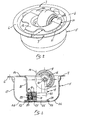
- Fig. 2 is a perspective view of the combination of a swivel caster and the device according to the invention,
- Fig. 3 is a cross-sectional view of the swivel caster and device according to Fig.2;
- Fig. 4 is a perspective view of another combination of a swivel castor/device arrangement;
- Fig. 5 is a cross-sectional view of the combination according to Fig. 4;
- Fig. 6 is a cross-sectional view of a combination swivel caster/device which caster wheel on its rolling bearing and the detachable protection plate both being applied on the same shaft;
- Fig. 7 is a cross sectional view of a swivel caster/device combination showing the application of two wheel bearings and an integrated safety-plate on the same wheel shaft.
-
- It is noted that for the same elements as shown in the figures also the same numbers will be applied.
According to Fig. 1 a part of a transportation system, a so-called roller platform 1 is shown in perspective. Such a platform, suitable for shipping of heavy crates or containers, is usually constructed according to a specially assembled bearing system and/or framework. To this purpose the system comprises a bottom platform 2 and anupper platform 3. For transportation of thefreight swivel casters 4 are preferably mounted at regular distances from each other in the upper platform 1. According to the invention the completeswivel casters 4 are now nearly fully enclosed in thedevise 5 which is mounted in saidupper platform 3.
According to Fig. 2devise 5 according to its cross sectional view mainly has the shape of a pot or bowl whichopen end 13 is provided with anedge 6. In thisedge holes 7 are applied which are suitable to be used as bolt or screw connections. According to the invention in the transportation system 1 theedge 6 of thedevise 5 is applied on to theupper platform 3 and it may be fastened on it by bolts (not shown). In thedevise 5 theswivel caster 8 is mounted such that only a part of thewheel 9 extends outside the surface of said upper platform. Generally the wheel-shaft 10 is at some distance below the surface of theupper platform 3. Overwheels 9, as known, freights can be moved in various directions. Preferable awheel 9 is applied on itsshaft 10 by a rolling bearing, see in particular Fig 7part 47,. This shaft further is part of a swivel fork 11, see also Fig. 3. According to the invention in this embodiment from the swivel fork 11 a protection orsafety plate 12 is developed which design will be discussed during the explanation of Fig. 3. - The
plate 12 offers a protection against e.g. foot injuries of persons working at the loading stations where these transportation systems are in operation or falling dirt and the like into the swivel casters which will certainly block the function of the system. Theplate 12 closes for a great part the devise opening 13. This plate has towards thewheel 9 some cut outs on to which theplate parts 12a, 12b are attached to theshaft 10. By thisplate embodiment wheel 9 can continuously freely swivel around itsswivel axle 14 as well asplate 12.
Fig. 3 shows the cross-section over the combination ofdevise 5 andswivel caster 8 such as it is mounted in the roller-platform 1.Devise 5 which has the shape of a bowl or pot which is executed with a relativelythin wall 15. The combination is therefor relatively light in weight and due to its shape sufficiently stiff. Thewheel 9 is applied on theshaft 10 which is attached with thelegs 16 of fork 11. The body or supporting element 17 of the fork is fastened to thejournal 19 of the rolling bearing 20 by a welded seam 18. According to the invention, theprotection plate 12 is developed from the element 17 in arunning plate part 21, preferably parallel to thewall 15 of the bowl-shaped devise 5 and passes into thehorizontal plate part 12. This part further is directed towards and approximately being in the same plane as theedge 6 of thedevise 5. According to the embodiment of Fig. 2 the casing of the rollingbearing 20 is formed by thejournal 19 and a so-calledtop plate 22 which at its bottom comprises anedge 23. According to the invention the attachment of the rollingbearing 20 is effected in the devise 5 by bending theedges 24 ofopenings 26 formed in the bottom 25 around theedge 23 of saidtop plate 22 and pressing them against this edge.
Another advantage of this bottom construction is characterized in that dirt and/or moisture that have fallen into the combined caster/devise 8,5 can be discharged along theseopenings 26. To strengthen this attachment a cap orring 27 is applied additionally which lies against the outer bearing ring of the rollingbearing 20. By these measures a reliable rolling bearing attachment of thecombination bearing 20 is further closed by a sealing means 28.
In the embodiment according to Fig. 2 and 3 theplate 12 is attached to thejournal 19 via the welded seam 18 and therefore forms an integrated protection plate of the combination swivel caster/devise 8,5. - Fig. 4 shows in perspective especially a different shape of the
protection plate 29 and swivelfork 30 as well.Plate 29 is connected with itsends wheel shaft 10 and the plate therefore can swivel along with thewheel 9. The other side ofplate 29 that is directed away fromwheel 9 is connected with the body or supportingelement 34 of theswivel fork 30 and on one side supported bystrips 33. The design ofswivel fork 30 that is adjusted thereto, particularly thebody 34 with regard to itsstrips 33, will be further explained by the description of Fig. 5.
According to the embodiment of Fig. 5 theswivel fork 30 is also assembled by the body 34and itslegs 36 however, of a somewhat different shape. On thelegs 36 thewheel shaft 10 is mounted on which theend parts plate 29 are attached by means of a connectingpiece 35. A part of the rolling bearing casing is formed by apart 37 of thebody 34 to which the inner ring of thebearing 20 is fixed. The outer ring of thebearing 20 is also fixed by thetop plate 22 such as in the embodiment according to Fig. 2 and 3. Thebody part 37 is then extended in abent edge part 38 against which ends of thestrips 33 lie or press. The pressing force is here determined by the direction and the attachment of theplate 29 on thewheel shaft 10. Contrary to the embodiment according to the Fig. 2 and 3 in which theprotection plate 12 is tightly attached to thejournal 19 of the rolling bearing, according to the embodiment of the Fig. 4 and 5 theprotection plate 29 is detachably connected with theshaft 10 andbody 34 of theswivel fork 30.
Fig. 6 and Fig. 7 also partly show a cross-sectional view of the combination swivelcaster 8 and devise 5 according to the invention. According to this embodiment the protection plate 41 which is in cross-section angular and detachable, is attached on to thewheel axle 10 against thelegs 40 of theswivel fork 39. The legs 42 of the plate 41 are mounted against those of theswivel fork 39. Favourable is in this embodiment is the wheel shaft design wherebywheel 9 is attached to thewheel shaft 10 by means of the rollingbearing 43. The rolling bearing is fixed on the shaft by applying thecap 44. According to the embodiment of Fig. 7 the angularity shapedprotection plate 45 is attached to thewheel shaft 10 and to the legs of the swivel fork 46 as well. However, thewheel 9 is supported on theshaft 10 by two rollingbearings 47. Both rollingbearings 47 are provided by retainingcaps 48 near the ends of the shaft. - The designs of the wheels and rolling bearings of the swivel casters as well as the protection plates depend on the demands that are made of the transportation system; e.g. for moving and/or manoeuvring relatively heavy containers transportation systems with double executed swivel casters will be preferred.
A protection plate, for that purpose, may have any suitable shape and be manufactured of suitable material e.g. metal or artificial fibre. Distinctive of this requirement always is that the plate swivels along with wheel and fork such that it e.g. prevents injuries of operating personnel by foot entering into the swivel caster. Further preventing penetrating of coarse material and therefore causing damages of the swivel caster.
The invention, for that matter, is not limited to the embodiments as shown ; e.g. a devise 5 according to its cross-section may have a flattened or trapezium hat shape or possess a polygonal shape and/or be manufactured from suitable material, for instance steel or artificial fibre framework and therefore be lighter in weight. It is, however, decisive that the devise 5 is always sufficiently strong and stiff to be able to guarantee a reliable functioning of the swivel casters and finally of the transportation system and still is easy to handle when removing it from or placing it on the system.
Claims (12)
- Swivel caster suitable to be mounted in a transportation system which caster mainly consists of a wheel secured on a shaft by means of a rolling bearing, said shaft being attached near its ends to the legs of a swivel fork which body or supporting-element is connected with the casing of a rolling bearing which casing can be mounted on said transportation system, said system mainly consists of a supporting platform composed of two plates an upper one from which said caster wheel partly extends and a bottom on which said bearing casing can be mounted, characterized in that said swivel caster (8) being completely mounted in a device (5) which opening has a rim (6) that can be connected on said upper plate (3) such that e.g. replacement of a swivel caster will be carried out only by removing said device (5) from said upper platform.
- Swivel caster according to claim 1, characterized in that said device (5) is a deepened block-shaped element, in which said bearing (20) being the swivel bearing is mounted on its bottom (25) and wherein its open end (13) is largely covered by a plate (12) which is connected to the wheel-shaft (10).
- Swivel caster according to conclusion 1 or 2, characterized in that said device (5) according to its cross-section has the shape of a relatively thin-walled bowl, pot or the like which at its open end being provided with an outer edge (6) having means (7) due to which said device (5) can be connected with the upper platform (3) of the system (1).
- Swivel caster according to claim 1 - 3, characterized in that the bottom (25) of said device (5) is provided with a number of openings (26) having edges (24) which are tightened around the edge (23) of the top plate or outer casing (22) of said rolling bearing (20), such that the swivel caster (8) is fastened in said device (5).
- Swivel caster according to claim 1 - 4, characterized in that said plate (12), which is a protecting or safety, means being part of the supporting element (17) of said swivel fork (11) and as well being part of the connection to the shaft (10) of said wheel (9).
- Swivel caster according to one or more of the previous claims and claim 5, characterized in that the supporting element (17) of said swivel fork (11) is attached to a journal (19) to which the rolling bearing (20) is connected and develops from it into said safety-plate (12).
- Swivel caster according to one or more of the previous claims, characterized in that one end of a safety-plate (29) is attached to said wheel shaft (10) by a connecting piece (35) whilst the other end directed to the edge (6) of said device (5) being provided with one or more strips (33) supporting against the edge (38) of the fork-body (36).
- Swivel caster according to claim 7, characterized in that the fork (30) from said wheel (9) to the rolling bearing (20) develops into a bearing casing (37) which is connected to the inner ring of said rolling bearing (20).
- Swivel caster according to one or more of the previous claims, characterized in that the outer ring of said rolling bearing (20) is connected to a so-called top plate or bearing outer casing (22) of said swivel caster (8) which edge (23) is fixed to the bottom (25) of said device (5).
- Swivel caster according to one or more of the previous claims, characterized in that the outer ring of the bearing (20) at its bottom is supported by a locking cap (27).
- Swivel caster according to one or more of the previous claims and claim 1, characterized in that it comprises at least two sealed rolling bearings (20,47).
- Swivel caster according to one or more of the previous claims, characterized in that a detachable protection plate (41) in cross-section having an angular shape is mounted against the legs (40) of a swivel fork (39) and said shaft (10).
Applications Claiming Priority (2)
| Application Number | Priority Date | Filing Date | Title |
|---|---|---|---|
| NL1018366 | 2001-06-22 | ||
| NL1018366A NL1018366C2 (en) | 2001-06-22 | 2001-06-22 | Swivel castor mounting element. |
Publications (2)
| Publication Number | Publication Date |
|---|---|
| EP1270407A1 true EP1270407A1 (en) | 2003-01-02 |
| EP1270407B1 EP1270407B1 (en) | 2008-04-23 |
Family
ID=19773604
Family Applications (1)
| Application Number | Title | Priority Date | Filing Date |
|---|---|---|---|
| EP02077439A Expired - Lifetime EP1270407B1 (en) | 2001-06-22 | 2002-06-20 | Swivel caster |
Country Status (5)
| Country | Link |
|---|---|
| US (1) | US6854159B2 (en) |
| EP (1) | EP1270407B1 (en) |
| AT (1) | ATE393089T1 (en) |
| DE (1) | DE60226198T2 (en) |
| NL (1) | NL1018366C2 (en) |
Families Citing this family (11)
| Publication number | Priority date | Publication date | Assignee | Title |
|---|---|---|---|---|
| US7143472B2 (en) * | 2003-10-10 | 2006-12-05 | Gary Dwayne Hicks | Caster thread guard and caster assembly |
| US20090261215A1 (en) * | 2008-04-16 | 2009-10-22 | Donald Lambert | Intravenous pole and base protection system |
| CN201392625Y (en) * | 2008-12-12 | 2010-01-27 | 鸿富锦精密工业(深圳)有限公司 | Display device |
| US8739364B2 (en) | 2012-07-10 | 2014-06-03 | Xerox Corporation | Protected caster assembly |
| US9119755B2 (en) * | 2012-09-07 | 2015-09-01 | Medcare Products, Inc. | Low profile rolling support assembly |
| US8534685B1 (en) * | 2012-09-25 | 2013-09-17 | Fred A. Tohm, Sr. | Roller assembly for traveling over surfaces |
| US9914327B2 (en) * | 2014-04-24 | 2018-03-13 | Ingenious Designs Llc | Caster wheel assembly |
| US10232667B2 (en) * | 2015-02-12 | 2019-03-19 | Nansin Co., Ltd. | Mounting structure for caster |
| US11235617B1 (en) * | 2020-12-10 | 2022-02-01 | Sam Rabi | Platform transport wheel assembly and method of use |
| JP7283796B2 (en) * | 2021-09-09 | 2023-05-30 | 株式会社ナカムラ | caster |
| DE102024119235B4 (en) | 2024-07-05 | 2026-01-22 | Deutsche Post Ag | Device for providing a barrier, use and roller deck |
Citations (5)
| Publication number | Priority date | Publication date | Assignee | Title |
|---|---|---|---|---|
| EP0152157A2 (en) * | 1984-02-13 | 1985-08-21 | Skf Transportwielen B.V. | Swivel caster |
| US5655259A (en) * | 1996-09-23 | 1997-08-12 | Look; Dick J. | Caster assembly |
| DE19720224A1 (en) * | 1997-03-24 | 1998-10-01 | Telair Int Gmbh | Ball mat for aircraft cargo decks |
| US6223388B1 (en) * | 1995-10-08 | 2001-05-01 | Revvo Castor Company Limited | Castor assembly |
| US6244417B1 (en) * | 1998-07-30 | 2001-06-12 | Fmc Corporation | Material handling unit with multidirectional helical roller assemblies |
Family Cites Families (12)
| Publication number | Priority date | Publication date | Assignee | Title |
|---|---|---|---|---|
| US2088093A (en) * | 1934-09-28 | 1937-07-27 | Henney Motor Co | Casket table caster for hearses |
| US3466697A (en) * | 1968-05-10 | 1969-09-16 | Bearings Seals & Gears Inc | Ball transfer or caster unit |
| US3739894A (en) * | 1971-03-15 | 1973-06-19 | Western Gear Corp | Ball transfer unit |
| US4125183A (en) * | 1977-08-22 | 1978-11-14 | Lang Robert D | Roller assembly |
| US4316305A (en) * | 1980-06-13 | 1982-02-23 | Wil-Mat Corporation | Swivel caster assembly |
| US4696583A (en) * | 1984-05-25 | 1987-09-29 | The Boeing Company | Ball support assembly |
| US5097565A (en) * | 1989-11-17 | 1992-03-24 | The Boeing Company | Cargo caster bearing assembly |
| DE3943185A1 (en) * | 1989-12-28 | 1991-07-04 | Bavaria Cargo Tech | STEERING WHEEL UNIT |
| US5134753A (en) * | 1991-01-18 | 1992-08-04 | Firma Sudhaus Schloss- Und Beschlagtechnik Gmbh & Co. | Luggage caster |
| DE4115708C2 (en) * | 1991-05-14 | 1995-01-12 | Telair Int Cargo Sys Gmbh | Ball roller unit |
| JP3498497B2 (en) * | 1996-09-30 | 2004-02-16 | 株式会社ダイフク | Fluid shelf load braking device |
| US6604258B2 (en) * | 2001-07-18 | 2003-08-12 | The Boeing Company | Caster roller for cargo handling system |
-
2001
- 2001-06-22 NL NL1018366A patent/NL1018366C2/en not_active IP Right Cessation
-
2002
- 2002-06-20 EP EP02077439A patent/EP1270407B1/en not_active Expired - Lifetime
- 2002-06-20 AT AT02077439T patent/ATE393089T1/en not_active IP Right Cessation
- 2002-06-20 DE DE60226198T patent/DE60226198T2/en not_active Expired - Fee Related
- 2002-06-21 US US10/178,901 patent/US6854159B2/en not_active Expired - Fee Related
Patent Citations (6)
| Publication number | Priority date | Publication date | Assignee | Title |
|---|---|---|---|---|
| EP0152157A2 (en) * | 1984-02-13 | 1985-08-21 | Skf Transportwielen B.V. | Swivel caster |
| NL8400460A (en) * | 1984-02-13 | 1985-09-02 | Skf Transportwielen Bv | SWIVEL WHEEL. |
| US6223388B1 (en) * | 1995-10-08 | 2001-05-01 | Revvo Castor Company Limited | Castor assembly |
| US5655259A (en) * | 1996-09-23 | 1997-08-12 | Look; Dick J. | Caster assembly |
| DE19720224A1 (en) * | 1997-03-24 | 1998-10-01 | Telair Int Gmbh | Ball mat for aircraft cargo decks |
| US6244417B1 (en) * | 1998-07-30 | 2001-06-12 | Fmc Corporation | Material handling unit with multidirectional helical roller assemblies |
Also Published As
| Publication number | Publication date |
|---|---|
| NL1018366C2 (en) | 2002-12-30 |
| ATE393089T1 (en) | 2008-05-15 |
| DE60226198T2 (en) | 2009-05-14 |
| NL1018366C8 (en) | 2002-10-30 |
| EP1270407B1 (en) | 2008-04-23 |
| US6854159B2 (en) | 2005-02-15 |
| US20030090075A1 (en) | 2003-05-15 |
| DE60226198D1 (en) | 2008-06-05 |
Similar Documents
| Publication | Publication Date | Title |
|---|---|---|
| EP1270407A1 (en) | Swivel caster | |
| US5947450A (en) | Manual swivel winch with open bottom | |
| EP2746133B1 (en) | Fastener and dolly | |
| CA3089028C (en) | Cargo bicycle which can be driven using muscle power and/or an electric drive | |
| US7849802B2 (en) | Protective housing assembly for a tank car manway | |
| CA2270012C (en) | Floating dock section | |
| US7849801B2 (en) | Protective housing assembly for a tank car manway | |
| WO2017031520A1 (en) | Water storage and transport system | |
| CA2070921C (en) | Mower deck | |
| US4893713A (en) | Protector pallet for aircraft wheel assemblies | |
| US6059299A (en) | Machine for transporting equipment | |
| US4961509A (en) | Bulk paint containers and method of making same | |
| EP0152157B1 (en) | Swivel caster | |
| US20050020151A1 (en) | Protective cage for an outboard motor and holding device thereof | |
| US7650920B2 (en) | Method and arrangement for increasing safety when handling a wheel | |
| EP1590596B1 (en) | Compressed gas container | |
| RU2124994C1 (en) | Railway tank car for liquid loads | |
| FI97039C (en) | Platform for transport of forest machines or the like | |
| RU2129979C1 (en) | Railway tank car | |
| US8807580B2 (en) | Axle assembly for agricultural applicator | |
| US20240067306A1 (en) | Temporary barge or boat hatch insert for facilitating void space | |
| US20030173357A1 (en) | Safety ramp for dumpster | |
| NL1010710C1 (en) | Hidden type quick release wheel hub assembly. | |
| JPS6139666Y2 (en) | ||
| US9623701B2 (en) | Skateboard with removable hub |
Legal Events
| Date | Code | Title | Description |
|---|---|---|---|
| PUAI | Public reference made under article 153(3) epc to a published international application that has entered the european phase |
Free format text: ORIGINAL CODE: 0009012 |
|
| AK | Designated contracting states |
Kind code of ref document: A1 Designated state(s): AT BE CH CY DE DK ES FI FR GB GR IE IT LI LU MC NL PT SE TR |
|
| AX | Request for extension of the european patent |
Free format text: AL;LT;LV;MK;RO;SI |
|
| 17P | Request for examination filed |
Effective date: 20030306 |
|
| AKX | Designation fees paid |
Designated state(s): AT BE CH CY DE DK ES FI FR GB GR IE IT LI LU MC NL PT SE TR |
|
| GRAP | Despatch of communication of intention to grant a patent |
Free format text: ORIGINAL CODE: EPIDOSNIGR1 |
|
| GRAS | Grant fee paid |
Free format text: ORIGINAL CODE: EPIDOSNIGR3 |
|
| GRAA | (expected) grant |
Free format text: ORIGINAL CODE: 0009210 |
|
| AK | Designated contracting states |
Kind code of ref document: B1 Designated state(s): AT BE CH CY DE DK ES FI FR GB GR IE IT LI LU MC NL PT SE TR |
|
| REG | Reference to a national code |
Ref country code: GB Ref legal event code: FG4D |
|
| REG | Reference to a national code |
Ref country code: CH Ref legal event code: EP |
|
| REF | Corresponds to: |
Ref document number: 60226198 Country of ref document: DE Date of ref document: 20080605 Kind code of ref document: P |
|
| REG | Reference to a national code |
Ref country code: IE Ref legal event code: FG4D Free format text: LANGUAGE OF EP DOCUMENT: FRENCH |
|
| PG25 | Lapsed in a contracting state [announced via postgrant information from national office to epo] |
Ref country code: FI Free format text: LAPSE BECAUSE OF FAILURE TO SUBMIT A TRANSLATION OF THE DESCRIPTION OR TO PAY THE FEE WITHIN THE PRESCRIBED TIME-LIMIT Effective date: 20080423 Ref country code: PT Free format text: LAPSE BECAUSE OF FAILURE TO SUBMIT A TRANSLATION OF THE DESCRIPTION OR TO PAY THE FEE WITHIN THE PRESCRIBED TIME-LIMIT Effective date: 20080923 Ref country code: ES Free format text: LAPSE BECAUSE OF FAILURE TO SUBMIT A TRANSLATION OF THE DESCRIPTION OR TO PAY THE FEE WITHIN THE PRESCRIBED TIME-LIMIT Effective date: 20080803 |
|
| PG25 | Lapsed in a contracting state [announced via postgrant information from national office to epo] |
Ref country code: AT Free format text: LAPSE BECAUSE OF FAILURE TO SUBMIT A TRANSLATION OF THE DESCRIPTION OR TO PAY THE FEE WITHIN THE PRESCRIBED TIME-LIMIT Effective date: 20080423 |
|
| ET | Fr: translation filed | ||
| PG25 | Lapsed in a contracting state [announced via postgrant information from national office to epo] |
Ref country code: DK Free format text: LAPSE BECAUSE OF FAILURE TO SUBMIT A TRANSLATION OF THE DESCRIPTION OR TO PAY THE FEE WITHIN THE PRESCRIBED TIME-LIMIT Effective date: 20080423 Ref country code: SE Free format text: LAPSE BECAUSE OF FAILURE TO SUBMIT A TRANSLATION OF THE DESCRIPTION OR TO PAY THE FEE WITHIN THE PRESCRIBED TIME-LIMIT Effective date: 20080723 Ref country code: MC Free format text: LAPSE BECAUSE OF NON-PAYMENT OF DUE FEES Effective date: 20080630 |
|
| REG | Reference to a national code |
Ref country code: CH Ref legal event code: PL |
|
| PLBE | No opposition filed within time limit |
Free format text: ORIGINAL CODE: 0009261 |
|
| STAA | Information on the status of an ep patent application or granted ep patent |
Free format text: STATUS: NO OPPOSITION FILED WITHIN TIME LIMIT |
|
| 26N | No opposition filed |
Effective date: 20090126 |
|
| REG | Reference to a national code |
Ref country code: IE Ref legal event code: MM4A |
|
| PG25 | Lapsed in a contracting state [announced via postgrant information from national office to epo] |
Ref country code: IE Free format text: LAPSE BECAUSE OF NON-PAYMENT OF DUE FEES Effective date: 20080620 |
|
| PG25 | Lapsed in a contracting state [announced via postgrant information from national office to epo] |
Ref country code: LI Free format text: LAPSE BECAUSE OF NON-PAYMENT OF DUE FEES Effective date: 20080630 Ref country code: CH Free format text: LAPSE BECAUSE OF NON-PAYMENT OF DUE FEES Effective date: 20080630 |
|
| PGFP | Annual fee paid to national office [announced via postgrant information from national office to epo] |
Ref country code: NL Payment date: 20090630 Year of fee payment: 8 |
|
| PGFP | Annual fee paid to national office [announced via postgrant information from national office to epo] |
Ref country code: IT Payment date: 20090617 Year of fee payment: 8 |
|
| PGFP | Annual fee paid to national office [announced via postgrant information from national office to epo] |
Ref country code: DE Payment date: 20090619 Year of fee payment: 8 |
|
| PG25 | Lapsed in a contracting state [announced via postgrant information from national office to epo] |
Ref country code: LU Free format text: LAPSE BECAUSE OF NON-PAYMENT OF DUE FEES Effective date: 20080620 Ref country code: CY Free format text: LAPSE BECAUSE OF FAILURE TO SUBMIT A TRANSLATION OF THE DESCRIPTION OR TO PAY THE FEE WITHIN THE PRESCRIBED TIME-LIMIT Effective date: 20080423 |
|
| PGFP | Annual fee paid to national office [announced via postgrant information from national office to epo] |
Ref country code: FR Payment date: 20100527 Year of fee payment: 9 |
|
| PG25 | Lapsed in a contracting state [announced via postgrant information from national office to epo] |
Ref country code: TR Free format text: LAPSE BECAUSE OF FAILURE TO SUBMIT A TRANSLATION OF THE DESCRIPTION OR TO PAY THE FEE WITHIN THE PRESCRIBED TIME-LIMIT Effective date: 20080423 |
|
| PG25 | Lapsed in a contracting state [announced via postgrant information from national office to epo] |
Ref country code: GR Free format text: LAPSE BECAUSE OF FAILURE TO SUBMIT A TRANSLATION OF THE DESCRIPTION OR TO PAY THE FEE WITHIN THE PRESCRIBED TIME-LIMIT Effective date: 20080724 |
|
| PGFP | Annual fee paid to national office [announced via postgrant information from national office to epo] |
Ref country code: BE Payment date: 20100430 Year of fee payment: 9 |
|
| PGFP | Annual fee paid to national office [announced via postgrant information from national office to epo] |
Ref country code: GB Payment date: 20100422 Year of fee payment: 9 |
|
| REG | Reference to a national code |
Ref country code: NL Ref legal event code: V1 Effective date: 20110101 |
|
| PG25 | Lapsed in a contracting state [announced via postgrant information from national office to epo] |
Ref country code: IT Free format text: LAPSE BECAUSE OF NON-PAYMENT OF DUE FEES Effective date: 20100620 |
|
| PG25 | Lapsed in a contracting state [announced via postgrant information from national office to epo] |
Ref country code: DE Free format text: LAPSE BECAUSE OF NON-PAYMENT OF DUE FEES Effective date: 20110101 |
|
| PG25 | Lapsed in a contracting state [announced via postgrant information from national office to epo] |
Ref country code: NL Free format text: LAPSE BECAUSE OF NON-PAYMENT OF DUE FEES Effective date: 20110101 |
|
| BERE | Be: lapsed |
Owner name: COLSON TRANSPORTWIELEN B.V. Effective date: 20110630 |
|
| GBPC | Gb: european patent ceased through non-payment of renewal fee |
Effective date: 20110620 |
|
| REG | Reference to a national code |
Ref country code: FR Ref legal event code: ST Effective date: 20120229 |
|
| PG25 | Lapsed in a contracting state [announced via postgrant information from national office to epo] |
Ref country code: BE Free format text: LAPSE BECAUSE OF NON-PAYMENT OF DUE FEES Effective date: 20110630 |
|
| PG25 | Lapsed in a contracting state [announced via postgrant information from national office to epo] |
Ref country code: FR Free format text: LAPSE BECAUSE OF NON-PAYMENT OF DUE FEES Effective date: 20110630 |
|
| PG25 | Lapsed in a contracting state [announced via postgrant information from national office to epo] |
Ref country code: GB Free format text: LAPSE BECAUSE OF NON-PAYMENT OF DUE FEES Effective date: 20110620 |