EP1270242A2 - Printer - Google Patents
Printer Download PDFInfo
- Publication number
- EP1270242A2 EP1270242A2 EP02013591A EP02013591A EP1270242A2 EP 1270242 A2 EP1270242 A2 EP 1270242A2 EP 02013591 A EP02013591 A EP 02013591A EP 02013591 A EP02013591 A EP 02013591A EP 1270242 A2 EP1270242 A2 EP 1270242A2
- Authority
- EP
- European Patent Office
- Prior art keywords
- cover
- printer
- platen
- transportation roller
- print head
- Prior art date
- Legal status (The legal status is an assumption and is not a legal conclusion. Google has not performed a legal analysis and makes no representation as to the accuracy of the status listed.)
- Granted
Links
Images


Classifications
-
- B—PERFORMING OPERATIONS; TRANSPORTING
- B41—PRINTING; LINING MACHINES; TYPEWRITERS; STAMPS
- B41J—TYPEWRITERS; SELECTIVE PRINTING MECHANISMS, i.e. MECHANISMS PRINTING OTHERWISE THAN FROM A FORME; CORRECTION OF TYPOGRAPHICAL ERRORS
- B41J29/00—Details of, or accessories for, typewriters or selective printing mechanisms not otherwise provided for
-
- B—PERFORMING OPERATIONS; TRANSPORTING
- B41—PRINTING; LINING MACHINES; TYPEWRITERS; STAMPS
- B41J—TYPEWRITERS; SELECTIVE PRINTING MECHANISMS, i.e. MECHANISMS PRINTING OTHERWISE THAN FROM A FORME; CORRECTION OF TYPOGRAPHICAL ERRORS
- B41J15/00—Devices or arrangements of selective printing mechanisms, e.g. ink-jet printers or thermal printers, specially adapted for supporting or handling copy material in continuous form, e.g. webs
- B41J15/04—Supporting, feeding, or guiding devices; Mountings for web rolls or spindles
- B41J15/042—Supporting, feeding, or guiding devices; Mountings for web rolls or spindles for loading rolled-up continuous copy material into printers, e.g. for replacing a used-up paper roll; Point-of-sale printers with openable casings allowing access to the rolled-up continuous copy material
-
- B—PERFORMING OPERATIONS; TRANSPORTING
- B41—PRINTING; LINING MACHINES; TYPEWRITERS; STAMPS
- B41J—TYPEWRITERS; SELECTIVE PRINTING MECHANISMS, i.e. MECHANISMS PRINTING OTHERWISE THAN FROM A FORME; CORRECTION OF TYPOGRAPHICAL ERRORS
- B41J11/00—Devices or arrangements of selective printing mechanisms, e.g. ink-jet printers or thermal printers, for supporting or handling copy material in sheet or web form
- B41J11/02—Platens
- B41J11/06—Flat page-size platens or smaller flat platens having a greater size than line-size platens
-
- B—PERFORMING OPERATIONS; TRANSPORTING
- B41—PRINTING; LINING MACHINES; TYPEWRITERS; STAMPS
- B41J—TYPEWRITERS; SELECTIVE PRINTING MECHANISMS, i.e. MECHANISMS PRINTING OTHERWISE THAN FROM A FORME; CORRECTION OF TYPOGRAPHICAL ERRORS
- B41J11/00—Devices or arrangements of selective printing mechanisms, e.g. ink-jet printers or thermal printers, for supporting or handling copy material in sheet or web form
- B41J11/66—Applications of cutting devices
- B41J11/70—Applications of cutting devices cutting perpendicular to the direction of paper feed
- B41J11/706—Applications of cutting devices cutting perpendicular to the direction of paper feed using a cutting tool mounted on a reciprocating carrier
Definitions
- the present invention relates to a printer that prints to a continuous sheet medium, and relates more particularly to a printer having a mechanism for retracting a platen from a proximal position opposite a print head in conjunction with a cover opening operation.
- This invention also relates to a printer for printing to continuous sheet media and single-sheet media, and relates more particularly to a printer having a diversion unit for diverting continuous sheet and single sheet media.
- Printers having a storage unit for internally storing a paper roll as a type of continuous sheet print medium and pulling the roll paper off the paper roll in the storage unit for printing are known.
- Printers of this type have an opening part that is opened and closed by a cover.
- a paper roll is typically replaced and the inside of the printer is maintained through this opening part.
- the paper When a paper roll is replaced, the paper must be pulled manually from the storage unit and set into the paper transportation path, and it is therefore preferable to locate the platen and transportation rollers forming one side of the paper transportation path on the side of the cover that opens and closes the opening to the storage unit.
- This configuration assures that the roll paper can be easily aligned in the paper transportation path when the cover is opened to change the paper roll because the platen and transportation rollers retract with the cover and thus open the paper transportation path.
- Printers that use a common print head to print on both continuous sheet media and single sheet forms have also become common.
- Printers of this type can print on single sheet forms for issuing receipts, invoices, tickets, coupons, and other such forms, and are widely used in supermarkets and retail stores.
- Printers of this type preferably guide both continuous sheet media and single sheet media to a common printing position, and then eject the different types of media from different exit openings after being printed.
- a diversion unit for diverting continuous sheet media and single sheet media to different exit paths is therefore required at a position downstream from the print head.
- the platen cannot be retracted with the cover in a printer that does not have a space in the platen retraction movement direction, and the diversion unit obstructs the platen retraction movement in printers that can print on both continuous sheet media and single sheet forms.
- the diversion unit can also interfere with opening and closing the cover. In addition to the diversion unit obstructing smooth opening and closing of the cover in this case, damage to the diversion unit or parts on the cover side could also result.
- JP-A-2000-118064 proposes retracting the platen in conjunction with the cover while avoiding interference with the paper exit diversion unit and other parts inside the printer by adding an operation for retracting the platen from an operative position (a position closely opposite the print head) in conjunction with a cover opening action and advancing the platen to the operative position in conjunction with a cover closing action.
- JP-A-2000-118064 achieves this action by using a large slide mechanism in order to retract the platen from the operative position opposite the print head, and thus presents problems such as described below.
- the present invention is directed to solving these problems and an object of the invention is to provide a printer which can retract the platen and transportation rollers while avoiding interference with internal printer parts when opening the cover, does not obstruct smooth opening and closing of the cover, invite an increase in printer size, or require a wide space around the printer, and can accurately position the platen to prevent print defects and form transportation problems.
- a further object of the invention is to provide a printer having a diversion unit at a position downstream from the print head for diverting continuous sheet media and single sheet media. More particularly, this printer automatically retracts the diversion unit during a cover opening operation to a position where the diversion unit will not interfere with cover opening and closing, thereby enabling a smooth cover opening operation and preventing damage to the diversion unit.
- This printer can also improve the operability of the cover opening operation by releasing the cover lock and retracting the diversion unit as a result of linear operation of the cover release button.
- the configuration of the present invention does not interfere with smooth opening and closing of the cover, invite an increase in printer size, or require a wide space around the printer.
- a first movable transportation roller is preferably disposed at the free end side of the platen for transporting the continuous sheet medium between the first movable transportation roller and a first fixed transportation roller disposed on the frame side.
- the continuous sheet medium can be easily aligned to the paper transportation path when the cover is closed.
- a second movable transportation roller is disposed at the fixed end side of the platen for transporting the continuous sheet medium between the second movable transportation roller and a second fixed transportation roller disposed on the frame side.
- Continuous sheet medium transportation problems can thus be prevented by transporting the paper with a pair of first and second transportation rollers.
- by holding the continuous sheet medium with the first and second movable transportation rollers when the cover is closed appropriate tension can be applied to the continuous sheet medium and printing defects caused by slack in the continuous sheet medium can be prevented.
- the first movable transportation roller contacts the first fixed transportation roller on the upstream side of the print head after the second movable transportation roller contacts the second fixed transportation roller on the downstream side of the print head when the cover is operated to close.
- the first and second movable transportation rollers apply pressure to the continuous sheet medium at different times, and as a result problems such as excessive force acting on the continuous sheet medium and the transportation rollers, and applying pressure to the continuous sheet medium while there is slack in the paper, can be avoided.
- a positioning guide part is disposed on the free end side of the platen for guiding the platen into position when the cover is operated to close. This accurately positions the platen and thus prevents printing defects and transportation problems.
- the abutment substantially stops rotation of the platen near the fully closed position of the cover, and engages the positioning guide part with a fixed guide pin on the housing side. The platen can thus be positioned accurately.
- the guiding direction of the positioning guide part is further preferably substantially perpendicular to the direction in which the platen escapes from the print head. Movement of the platen away from the print head is thus reliably restricted by the positioning guide parts, and printing defects caused by the platen separating from the print head can be prevented.
- the first movable transportation roller can be accurately positioned to the first fixed transportation roller, and paper transportation problems due to an offset in the positions of the transportation rollers, can be prevented.
- a first movable transportation roller is disposed on the free end side of the platen for transporting the continuous sheet medium between the first movable transportation roller and a first fixed transportation roller on the frame side.
- the support axis (shaft) of the first movable transportation roller is also positioned on the print head side of an imaginary line passing through the center of platen rotation and the center of first fixed transportation roller rotation as seen in a side view. It is therefore possible to press and position the platen to the print head using the first fixed transportation roller and first movable transportation roller. The number of parts can therefore be reduced and the structure simplified compared with a configuration using special platen presser or platen positioning members.
- accommodating means allowing the first movable transportation roller to pass over the first fixed transportation roller in conjunction with opening and closing the cover are provided. This reduces the load of the first movable transportation roller as it moves over the first fixed transportation roller, thus avoids deformation of or damage to members when the movable transportation roller rides over the fixed transportation roller, and avoids problems interfering with smooth opening and closing of the cover.
- the print head can print to continuous sheet media and a single-sheet media
- the printer additionally has a diversion unit disposed downstream from the print head on the frame side for diverting the continuous sheet medium and single-sheet form P2 to respective paths.
- the diversion unit can be retracted to a position not interfering with opening and closing the cover.
- the diversion unit can be automatically retracted when the cover is opened or closed to a position not interfering with opening and closing the cover. Interference between the diversion unit and platen is therefore reliably avoided, the cover can be smoothly opened, and damage to the diversion unit can be avoided.
- the abutment is positioned near the diversion unit.
- the platen can be made as small as possible and the abutment is prevented from interfering with replacing the continuous sheet medium.
- the second fixed transportation roller at the diversion unit and transporting the continuous sheet medium on the downstream side of the print head, slack can be prevented in the continuous sheet medium, and the medium can be reliably transported to and past the diversion unit.
- the diversion unit is also used as the support member for the second fixed transportation roller, the part count can be reduced and the construction can be simplified.
- the diversion unit is configured to pivot freely in an advancing-retracting direction relative to the continuous sheet medium transportation path or second movable transportation roller, and is urged by a presser spring in the advancing direction.
- the diversion unit can therefore be smoothly retracted when there is contact with the movable platen, and pressure can be applied reliably to the paper due to the urging force of the presser spring.
- the diversion unit has a fixed knife for cutting the continuous sheet medium
- the diversion unit is also used as the support member for the fixed knife. This further reduces the part count and simplifies the structure.
- the printer has a cover release button disposed on the frame side and operated in a straight line, and a cover locking mechanism for locking the cover in a closed position.
- the cover locking mechanism enables the cover to be opened when the cover release button is operated, and thus enables the diversion unit to move to the retracted side.
- the cover locking mechanism has lock pins disposed on the frame side; lock levers rotatably disposed at the frame side for engaging and releasing the lock pins; and a lock release lever rotatably disposed at the frame side.
- lock release lever moves the lock levers to disengage and release the lock pins, and move the diversion unit to the retracted side. That is, while the cover release button travels in a straight line it moves the lock levers and diversion unit by way of a pivoting lock release lever, thereby reducing the force needed to operate the cover release button and further improving the operability of the cover opening operation.
- the lock release lever has a first lever part linked to the cover release button; a second lever part linked to the lock levers and the diversion unit; and a connecting part integrally linking the first and second lever parts.
- the first and second lever parts are pivotally supported. This configuration increases lock release lever strength, enables the lock release lever to operate smoothly, and thus further improves the operability of the cover opening operation.
- a lock release lever support part (lock release lever support member and side frame) supporting the lock release lever to pivot freely comprises a rotation support part enabling attaching the lock release lever from a lateral direction outside the normal rotation range; and a stopper limiting lateral movement of the lock release lever in the normal rotation range. Rotation of the lock release lever to outside the normal rotation range is limited by the cover release button. A special member for limiting lateral movement of the lock release lever is thus unnecessary, and the part count and the number of assembly steps can therefore be reduced and the structure can be simplified.
- first or second lever part has a notched part contiguous to the pivot hole
- the rotation support part has a narrow part to which the notched part fits and a pivot shaft part protruding horizontally from the narrow part.
- the pivot hole can be fit to the pivot shaft part when the notched part is fit to the narrow part. It is therefore possible to install the lock release lever to the rotation support part using a simple configuration having a notched part formed in the lock release lever and a narrow part formed to the rotation support part.
- the printer 10 comprises a printer unit 11 with a cover 12 (a housing member).
- the printer 10 has a paper storage unit 13 for storing a paper roll P1 (a continuous sheet medium), and a form insertion opening 14 for inserting a single-sheet form P2 (single sheet medium).
- the roll paper transportation path and the single-sheet transportation path are configured to transport roll paper, which is pulled out from the paper roll P1 in storage unit 13, and transport a single-sheet form P2, which inserted into the form insertion opening 14, to and past a common printing position 15.
- a print head 16 and a movable platen 17, in its operating position, are disposed opposite each other and define the printing position 15 between them. Downstream therefrom is disposed a diversion unit 18 for diverting the paper roll P1 and single-sheet form P2 to corresponding ejection paths.
- the print head 16 can be, for example, an inkjet print head mounted on a carriage (not shown in the figure) that travels bidirectionally widthwise to the paper transportation path for dot matrix printing on the surface of roll paper or single-sheet form P2 backed by the platen 17.
- Roll paper pulled out from the paper roll P1 passes between a first fixed transportation roller 19 (drive roller) and first movable transportation roller 20 (pinch roller) to the printing position 15, and passes between a second fixed transportation roller 21 (pinch roller ) and second movable transportation roller 22 (drive roller) and by a cutter mechanism 48 (further described below) behind the diversion unit 18 before being ejected from roll paper exit 23.
- a single-sheet form P2 inserted into form insertion opening 14 passes between a pair of single-sheet transportation rollers 24 to the printing position 15 on the downstream side of rollers 24, and passes in front of the diversion unit 18 to exit from the single-sheet form exit 25.
- An opening 26 (see Fig. 6) is formed above the paper storage unit 13, and the paper roll P1 is replaced through this opening 26.
- the opening 26 is opened and closed by a cover 28 hinged at the back of a unit frame 27 (a housing member) so as to rotate freely up and down about a pivot axis that extend substantially in parallel to axis of the paper roll P1 and the stroke of the print head 16.
- the cover 28 is supported to rotate freely up and down pivoting on burring parts 28a fit into pivot holes (not shown in the figure) in the side frames 46 of the unit frame 27.
- a pair of right and left lock levers 29 is disposed freely rotatable back and forth on the cover 28 about a pivot axis that extends in parallel to that of the cover 28.
- the lock levers 29 engage lock pins 30 disposed on the unit frame 27 and thus automatically lock the cover 28 in its closed position.
- a cover release button 31 further described below is operated to disengage the lock levers 29 and unlock the cover 28.
- One end of the platen 17 is pivotally supported at the free end part of the cover 28 by way of platen support shaft 32 that extends in parallel to the pivot axis of the cover 29.
- the first movable transportation roller 20 is disposed on a roller shaft 33 at the free end side of the platen 17, and the second movable transportation roller 22 is disposed on platen support shaft 32 at the fixed (supported) end side.
- a transfer gear mechanism 34 is disposed at one side of the platen 17.
- the second movable transportation roller 22, which is the drive roller, is linked to the transportation motor (not shown in the figure) through transfer gear mechanism 34 when the cover 28 is fully closed, and is thus rotationally driven by power from the transportation motor.
- the platen 17 is urged to the bottom side of the cover 28 by an elastic retraction mechanism 60 (see Fig. 15), i.e., a tension coil spring stretched between a side of the platen 17 and the bottom side of the cover 28, so that when the cover 28 is open the urging force of the elastic retraction mechanism 60 holds the platen 17 to the bottom of the cover 28 (in the inoperative position of the platen).
- an elastic retraction mechanism 60 i.e., a tension coil spring stretched between a side of the platen 17 and the bottom side of the cover 28, so that when the cover 28 is open the urging force of the elastic retraction mechanism 60 holds the platen 17 to the bottom of the cover 28 (in the inoperative position of the platen).
- the bottom of the cover is that part that faces the paper storage unit 13 when the cover is closed.
- An abutment 35 for rotating platen 17 between it inoperative and operative positions in conjunction with the opening and closing motion of the cover 28 is disposed proximally above the diversion unit 18 on the unit frame 27 side.
- the abutment 35 is engaged by the pair of right and left engagement levers 36 protruding at the fixed end side of the platen 17 to swing the platen 17 between its two positions relative to the cover.
- the basic operation of platen 17 is further described below with reference to Figs. 6 to 11.
- Fig. 6 is a side view of the printer unit when the cover 28 is in the full open position.
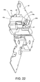
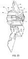
- the platen 17 is held in a position along the bottom of the cover 28 by the urging force of the elastic retraction mechanism 60 when the cover 28 is fully open and a wide space is open above the paper storage unit 13.
- One side of the roll paper transportation path is opened by retracting the platen 17, first movable transportation roller 20, and second movable transportation roller 22 in conjunction with the cover 28.
- cover 28 is thus open, paper roll P1 can be loaded into the paper storage unit 13 and the end of the paper roll P1 can be fed into the roll paper transportation path from the paper storage unit 13.
- Fig. 7 is a side view of the printer unit when the cover is about half open
- Fig. 8 is a side view of the printer unit when the engagement levers contact the abutment
- Fig. 9 is a side view of the printer unit when the platen starts to rotate away from the cover 28
- Fig. 10 is a side view of the printer unit just before the cover reaches the fully closed position.
- the engagement levers 36 of the platen 17 engage abutment 35.
- the engagement levers 36 which are restricted by the abutment 35 from moving further down, rotate clockwise relative to the cover 28 (as viewed in Fig. 8), causing the platen 17 to rotate downward and forward away from the cover bottom and against the urging force of the elastic retraction mechanism 60.
- the platen 17 thus rotates downward and forward together with cover 28, and enters the space below the diversion unit 18.
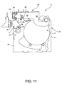
- Fig. 11 is a side view of the printer unit when the cover is in the fully closed position.
- the platen 17 has reached its operative position opposite the print head 16, first movable transportation roller 20 and second movable transportation roller 22 press the roll paper to the first fixed transportation roller 19 and second fixed transportation roller 21, respectively, and the printer 10 is ready to print.
- the cover 28 When the cover 28 is thus fully closed and the cover release button 31 is operated, the cover 28 can be opened.
- action opposite that of the closing operation and the urging force of the elastic retraction mechanism 60 cause the engagement levers 36 to rotate relatively forward (i.e., counterclockwise as viewed in Fig.7 to 11), thus causing the platen 17 to rotate toward its inoperative position at the bottom of the cover 28.
- the platen 17 thus rotates up and back in conjunction with the opening motion of the cover 28, and retracts from the space below the diversion unit 18.
- first the second movable transportation roller 22 contacts the second fixed transportation roller 21 downstream from print head 16, and subsequently the first movable transportation roller 20 contacts the first fixed transportation roller 19 upstream from the print head 16.
- the offset in the timing at which the first and second movable transportation rollers 20, 22 apply pressure to the roll paper it is possible to avoid such problems as applying excessive force to the roll paper or the first and second movable transportation rollers 20, 22 applying pressure to the roll paper with slack in the paper.
- the platen 17 has positioning guide parts 37 on the free end side on both right and left side parts.
- the positioning guide parts 37 each have a guide channel 37a (see Fig. 6) with an opening to the bottom side, i.e., the side opposite to the platen support shaft 32.
- the positioning guide parts 37 engage a respective guide pin 38 (fixed guide part) fixed on the corresponding unit frame side to precisely position the platen 17 in its operative position. More specifically, as shown in Fig. 10, when the cover 28 is closed to the position just before the fully closed position, the abutment 35 substantially stops rotation of the platen 17, and the platen 17 descends substantially vertically with slight free rotation allowed.
- An inclined guide surface 37b (see Fig.
- the guiding direction (engaging direction) of the guide channel 37a is substantially perpendicular to the direction in which the platen 17 separates from the print head 16, and is substantially perpendicular to a line tangent to the first movable transportation roller 20 and first fixed transportation roller 19.
- the positioning guide parts 37 thus reliably limit the escape of platen 17 from the print head 16, and also accurately position the first movable transportation roller 20 to the first fixed transportation roller 19.
- Fig. 12 is a perspective view of the diversion unit.
- the diversion unit 18 has a diverter plate 39 forming a single-sheet paper transportation path, a support member 40, and a fixed knife 41.
- the support member 40 is disposed on the back of the diverter plate 39 and freely rotatably axially supports the second fixed transportation roller 21.
- the fixed knife 41 is disposed at support member 40 and is used to cut the ejected part of the roll paper.
- the diversion unit 18 thus comprised is disposed to rotate freely back and forth on the unit frame 27 by way of diverter support shaft 42, and is urged to the platen 17 side (second movable transportation roller 22 side) by a presser spring 43 disposed at both right and left ends of the diverter support shaft 42.
- the diversion unit 18 is constructed so that it can retract to a position not interfering with cover 28 opening and closing operations, and to press the second fixed transportation roller 21 to the second movable transportation roller 22 with the urging force of presser springs 43 when the cover 28 is in the closed position to assure reliable paper transportation.
- one end of the presser springs 43 is engaged in a channel on the respective side of unit frame 27, and the other end is engaged by protrusion 40a of support member 40.
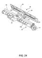
- Fig. 24 is a perspective view and Fig. 25 is a side view of the paper cutter mechanism.
- the paper cutter mechanism 48 has the fixed knife 41 disposed side to side on the diversion unit 18, a guide shaft 49 disposed side to side at the end side of the cover 28, a movable knife support member 50 freely movable side to side along the guide shaft 49, a rotating shaft 51 projecting downward from the front edge part of the movable knife support member 50, a rotary-type movable knife 52 disposed integrally to the bottom end part of the rotating shaft 51, and a cam shaft 53 for reciprocally moving the movable knife support member 50 side to side.
- the cam shaft 53 is supported at the free end side of the cover 28 to rotate freely and has a cam groove 53a formed in the outside surface thereof for producing a side to side movement.
- the cam groove 53a is an endless groove having two spiral grooves winding in opposite directions and connecting channel parts linking the ends of the spiral grooves.
- the cam groove 53a engages a follower member 54 freely rotatably coupled to the movable knife support member 50. This configuration causes the movable knife support member 50 and movable knife 52 to move reciprocally along the fixed knife 41 while the cam shaft 53 rotates in one direction.
- Drive power from the transportation motor is transferred to the cam shaft 53 via a cam shaft gear 57 disposed at the left end part of the cam shaft 53.
- a paper guide 55 is disposed from side to side between the rotating shaft 51 and the roll paper transportation path.
- This paper guide 55 functions as an exit guide for the roll paper and has a fixed rack 55a formed integrally to the back thereof from side to side.
- a gear 56 for rotating the movable knife is disposed integrally to the rotating shaft 51, and meshes with fixed rack 55a so that as the movable knife support member 50 moves the movable knife 52 is turned in an appropriate direction (the direction in which the edge of the movable knife 52 rotates toward the fixed knife 41).
- the rotating shaft 51 is positioned at an angle to the roll paper transportation path so that the down side (the movable knife 52 side) approaches the roll paper transportation path and the top side (the knife gear side) recedes from the roll paper transportation path. It is therefore possible to assure space for the fixed rack 55a (paper guide 55) between the roll paper transportation path and knife gear 56 while reducing the size of the movable knife 52.
- Fig. 13 is a perspective view of the entire printer unit showing the cover locking mechanism
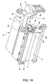
- Fig. 14 is a perspective view of the cover locking mechanism as seen from above
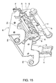
- Fig. 15 is a perspective view of the cover locking mechanism as seen from below.
- the cover locking mechanism 44 includes the above-described lock levers 29 disposed on the cover side, the lock pins 30 disposed on the unit frame side, and a lock release lever 45 for moving the lock levers 29 to the lock release side (unlocked position) according to the operation of the cover release button 31.
- the lock levers 29 each have a hook part 29a (see also Fig. 16) for engaging the lock pin 30, and an inclined guide part 29b (see also Fig. 16) for automatically engaging the lock pin 30.
- the lock levers 29 are disposed on right and left sides at the free end side of the cover 28.
- the base end parts of the pair of lock levers 29 are integrally linked by an intervening pipe-like connecting rod 29c, are supported so as to pivot freely back and forth on a lever support shaft 29d fit to connecting rod 29c, and are urged by a restoring spring 29e in the lock pin engaging direction.
- the lock pins 30 project to the inside part of the side frame 46, and engage the lock levers 29 to hold the cover 28 in the closed position.
- the lock release lever 45 has a first lever part 45a linked to the cover release button 31, a second lever part 45b linked to the lock levers 29 and diversion unit 18, and a connecting part 45c integrally connecting the top end parts of both lever parts 45a and 45b.
- the first lever part 45a has a button engaging part 45d for engaging the cover release button 31 (see Fig. 16), and a pivot hole 45e that is fit to rotation support part 47a of the lock release lever support member 47 further described below. The first lever part 45a is thus supported so that it pivots freely back and forth on pivot hole 45e.
- the second lever part 45b has a lock lever engaging part 45f for engaging the engaging tab 29f of the right side lock lever 29, a diverter engaging part 45g for engaging protrusion 40a of diversion unit 18, and a burring part 45h that is fit into a pivot hole (not shown in the figure) in the side frame 46.
- the second lever part 45b is thus supported to pivot freely back and forth on the burring part 45h.
- the cover release button 31 is affixed to the unit frame 27 so that the button can slide freely in a linear direction, and in this preferred embodiment of the invention is operated to be pushed straight down.
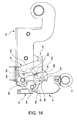
- Fig. 16 is a side view of the cover locking mechanism when the cover is in the fully closed position.
- lock levers 29 engage lock pins 30 and hold the cover 28 closed.
- the urging force of presser spring 43 also causes the diversion unit 18 to press second fixed transportation roller 21 to second movable transportation roller 22.
- Fig. 17 is a side view of the cover locking mechanism just after the cover release button 31 is operated
- Fig. 18 is a side view of the cover locking mechanism at the start of the cover opening operation.
- Fig. 19 (A) is a side view showing the pivot part of the lock release lever 45
- Figs. 19 (B), 19 (C), and 19 (D) are a plan view, front view, and side view, respectively, of the pivot part of the lock release lever support member 47.
- a notched part 45i open to the bottom and contiguous to the pivot hole 45e is formed in the first lever part 45a of lock release lever 45.
- the lock release lever support member 47 is a resin molding having rotation support part 47a integrally disposed to the right top part thereof.
- the rotation support part 47a has a flat narrow part 47b to which the notched part 45i of lock release lever 45 is fit from above, and a pivot shaft part 47c projecting to the right side from narrow part 47b.
- pivot hole 45e can be fit to the pivot shaft part 47c so that the first lever part 45a of lock release lever 45 is pivotally supported by the pivot shaft part 47c.
- the lock release lever 45 is first tilted forward (outside the normal range of rotation) and the notched part 45i of first lever part 45a is fit down onto the narrow part 47b of lock release lever support member 47 (see arrow (1) in Fig. 20).
- the lock release lever 45 is then slid to the right as seen in the figures to fit the pivot hole 45e in first lever part 45a to the pivot shaft part 47c of lock release lever support member 47, and fit the burring part 45h of second lever part 45b into the pivot hole in the side frame 46 (see arrow (2) in Fig. 20).
- the lock release lever 45 is rotated into the normal range of rotation and the engaging abutment 45j formed on the left end part of the lock release lever 45 is engaged with the stopper 46a formed on side frame 46 (see arrow (3) in Fig. 22). Sideways movement of the lock release lever 45 is thus limited by the second lever part 45b contacting the left side of the side frame 46 and the engaging abutment 45j engaging the stopper 46a from the right side.
- the cover release button 31 is then installed to the unit frame 27 so that it can slide freely up and down (see (4) in Fig. 23). Rotation of the lock release lever 45 beyond the normal range of rotation is thus limited by the cover release button 31.
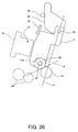
- Fig. 26 is a schematic side view showing the location of the first transportation roller pair.
- this alternative embodiment transports roll paper by means of first transportation roller pair 19, 20 on the upstream side of the print head 16 without providing the second transportation roller pair 21, 22 on the downstream side of the print head 16.
- the roller shaft 33 of first movable transportation roller 20 is disposed on the print head side of an imaginary line A passing through the center of the pivot axis of platen 17 (platen support shaft 32) and the center of first fixed transportation roller 19.
- roller tangent B tangent to first transportation roller pair 19, 20 slopes toward the print head 16, thus limiting movement of first movable transportation roller 20 away from the print head 16 and applying pressure pushing the first movable transportation roller 20 forward towards the print head 16.
- the platen 17 can thus be positioned using the first transportation roller pair 19, 20, and a specified gap can be formed between the platen 17 and print head 16.
- the roller shaft 33 is positioned as described above the first movable transportation roller 20 must be able to travel over the first fixed transportation roller 19 when the cover 28 is opened and closed.
- the roller shaft 33 is therefore supported in elliptical holes 17a (accommodating means) so that it can move freely up and down relative to the platen 17, and is urged downwardly by an elastic mechanism not shown in the figures.
- a printer 10 has a housing (including cover 12 and unit frame 27) with a paper storage unit 13 for holding paper roll P1, a cover 28 for opening and closing an opening 26 to paper storage unit 13, a print head 16 for printing on roll paper pulled off the paper roll P1 in the paper storage unit 13, a platen 17 disposed to rotate freely on the cover 28 for guiding the back of the paper roll P1 to a proximal position opposite the print head 16, and an abutment 35 for engaging the engagement levers 36 of the platen 17 and rotating the platen 17 in a contrary direction in conjunction with opening and closing the cover 28.
- the configuration of the present invention does not interfere with smooth opening and closing of the cover 28, invite an increase in printer size, or require much space around the printer.
- the roll paper can be easily aligned to the paper transportation path when the cover 28 is closed.
- first movable transportation roller 20 contacts the first fixed transportation roller 19 on the upstream side of the print head 16 after the second movable transportation roller 22 contacts the second fixed transportation roller 21 on the downstream side of the print head 16 when the cover 28 is operated to close, problems such as excessive force acting on the roll paper and the transportation rollers 20, 22 applying pressure to the roll paper while there is slack in the paper can be avoided.
- a positioning guide part 37 is disposed on the free end side of the platen 17 for guiding the platen 17 into position when the cover 28 is operated to close. This accurately positions the platen 17 and thus prevents printing defects and transportation problems.
- the abutment 35 substantially stops rotation of the platen 17 near the fully closed position of the cover 28, and engages the positioning guide part 37 with a fixed guide pin 38 on the housing side.
- the platen 17 can thus be positioned accurately.
- the guiding direction of the positioning guide part 37 is substantially perpendicular to the direction in which the platen 17 escapes from the print head 16. Movement of the platen 17 away from the print head 16 is thus reliably restricted by the positioning guide parts 37, and printing defects caused by the platen 17 separating from the print head 16 can be prevented.
- the first movable transportation roller 20 can be accurately positioned with respect to the first fixed transportation roller 19, and paper transportation problems due to an offset in the positions of the transportation rollers 19, 20 can be prevented.
- a first movable transportation roller 20 is disposed on the free end side of the platen 17 for transporting the roll paper between the first movable transportation roller 20 and the first fixed transportation roller 19 disposed inside the printer.
- the support axis (shaft) 33 of the first movable transportation roller is positioned on the print head side of an imaginary line passing through the center of rotation of the platen and the center of rotation of the first fixed transportation roller rotation as seen in a side view. It is therefore possible to press and position the platen 17 to the print head 16 using the first fixed transportation roller 19 and first movable transportation roller 20.
- the number of parts can therefore be reduced and the structure simplified compared with a configuration using special platen presser or platen positioning members.
- elliptical holes 17a (accommodating means) allowing the first movable transportation roller 20 to pass over the first fixed transportation roller 19 in conjunction with opening and closing the cover 28 are provided. This reduces the load of the first movable transportation roller 20 as it moves over the first fixed transportation roller 19, thus avoids deformation of or damage to members when the movable transportation roller rides over the fixed transportation roller, and avoids problems interfering with smooth opening and closing of the cover 28.
- the print head 16 can print on roll paper (continuous sheet medium) and single-sheet forms P2 (single sheet medium), and the printer additionally has a diversion unit 18 disposed downstream from the print head on the frame side for diverting the roll paper and single-sheet form P2 to respective paths.
- the diversion unit 18 can be retracted to a position not interfering with opening and closing the cover.
- the diversion unit 18 for diverting the paper roll P1 and single-sheet form P2 to separate exit paths is disposed downstream of the print head 16, the diversion unit 18 can be automatically retracted when the cover 28 is opened or closed to a position not interfering with opening and closing the cover 28. Interference between the diversion unit 18 and platen 17 is therefore reliably avoided, the cover 28 can be smoothly opened, and damage to the diversion unit 18 can be avoided.
- the abutment is positioned near the diversion unit 18.
- the platen 17 can be made as small as possible and the abutment 35 is prevented from interfering with replacing the paper roll P1.
- the second fixed transportation roller 22 By disposing the second fixed transportation roller 22 to the diversion unit 18 and transporting the roll paper on the downstream side of the print head 16, slack can be prevented in the roll paper, and the paper can be reliably transported passed the diversion unit.
- the diversion unit 18 is also used as the support member for the second fixed transportation roller 21, the part count can be reduced and the structure can be simplified.
- the diversion unit 18 is configured to rotate freely in an advancing-retracting direction relative to the roll paper (continuous sheet medium) transportation path or second movable transportation roller 22, and is urged by a presser spring 43 in the advancing direction.
- the diversion unit 18 can therefore be smoothly retracted when there is contact with the platen 17, and pressure can be applied reliably to the paper due to the urging force of the presser spring 43.
- the diversion unit 18 has a fixed knife 41 for cutting the roll paper
- the diversion unit 18 is also used as the support member for the fixed knife 41. This further reduces the part count and simplifies the structure.
- the printer has a cover release button 31 disposed on the frame side and operated in a straight line, and a cover locking mechanism 44 for locking the cover in a closed position.
- the cover locking mechanism 44 enables the cover to be opened when the cover release button is operated, and thus enables the diversion unit 18 to move to the retracted side.
- the cover locking mechanism 44 has lock pins 30 disposed on the frame side; lock levers 29 rotatably disposed at the frame side for engaging and releasing the lock pins 30; and a lock release lever 45 rotatably disposed at the frame side.
- the lock release lever 45 moves the lock levers 29 to disengage and release the lock pins, and move the diversion unit 18 to the retracted side. That is, while the cover release button 31 travels in a straight line it moves the lock levers 29 and diversion unit 18 by way of a pivoting lock release lever 45, thereby reducing the force needed to operate the cover release button 31 and further improving the operability of the cover opening operation.
- the lock release lever 45 has a first lever part 45a linked to the cover release button 31; a second lever part 45b linked to the lock levers 29 and the diversion unit 18; and a connecting part 45c integrally linking the first and second lever parts 45a, 45b.
- the first and second lever parts 45a, 45b are pivotally supported. This configuration increases lock release lever 45 strength, enables the lock release lever 45 to operate smoothly, and thus further improves the operability of the cover opening operation.
- a lock release lever support part (lock release lever support member 47 and side frame 46) supporting the lock release lever 45 to pivot freely comprises a rotation support part 47a enabling attaching the lock release lever 45 from a lateral direction outside the normal rotation range; and a stop part 46a limiting lateral movement of the lock release lever 45 in the normal rotation range. Rotation of the lock release lever 45 to outside the normal rotation range is limited by the cover release button 31. A special member for limiting lateral movement of the lock release lever 45 is thus unnecessary, and the part count and the number of assembly steps reduced can therefore be reduced and the structure can be simplified.
- the first lever part 45a has a notched part 45i contiguous to the pivot hole 45e
- the rotation support part 47a has a narrow part 47b to which the notched part 45i fits and a pivot shaft part 47c protruding horizontally from the narrow part 47b.
- the pivot hole 45e can be fit to the pivot shaft part 47c when the notched part 45i is fit to the narrow part 47b. It is therefore possible to mount the lock release lever 45 to the rotation support part 47a using a simple configuration having a notched part 45i formed in the lock release lever 45 and a narrow part 47b formed to the rotation support part 47a.
- an engagement lever 36 and abutment 35 engaging the engagement lever 36 are disposed on both side ends in the above embodiment, but could be disposed on only one end.
- the diverter support shaft 42 or the presser spring 43 coupled to the diverter support shaft 42 could alternatively be used as the abutment 35.
- the fixed transportation roller is described above as being on the drive side and the movable transportation roller as being on the driven (follower) side, but these could be reversed so that the fixed transportation roller is the driven (follower) side and the movable transportation roller is the drive side.
- a printer according to the present invention can retract the platen and transportation rollers while avoiding interference with internal printer parts when opening the cover, does not obstruct smooth opening and closing of the cover, does not invite an increase in printer size, does not require a wide space around the printer, and can accurately position the platen to prevent print defects and paper transportation problems.
- the printer has a diversion unit at a position downstream of the print head for diverting continuous sheet media and single sheet media
- the diversion unit is automatically retracted to a position where the diversion unit will not interfere with opening and closing the cover when the cover is opened.
- the cover can therefore be smoothly opened and closed, and damage to the diversion unit can be prevented.
- the operability of the cover opening operation is also improved by releasing the cover lock and retracting the diversion unit as a result of a linear operation of the cover release button.
Abstract
Description
- The present invention relates to a printer that prints to a continuous sheet medium, and relates more particularly to a printer having a mechanism for retracting a platen from a proximal position opposite a print head in conjunction with a cover opening operation. This invention also relates to a printer for printing to continuous sheet media and single-sheet media, and relates more particularly to a printer having a diversion unit for diverting continuous sheet and single sheet media.
- Printers having a storage unit for internally storing a paper roll as a type of continuous sheet print medium and pulling the roll paper off the paper roll in the storage unit for printing are known. Printers of this type have an opening part that is opened and closed by a cover. A paper roll is typically replaced and the inside of the printer is maintained through this opening part. When a paper roll is replaced, the paper must be pulled manually from the storage unit and set into the paper transportation path, and it is therefore preferable to locate the platen and transportation rollers forming one side of the paper transportation path on the side of the cover that opens and closes the opening to the storage unit. This configuration assures that the roll paper can be easily aligned in the paper transportation path when the cover is opened to change the paper roll because the platen and transportation rollers retract with the cover and thus open the paper transportation path.
- Printers that use a common print head to print on both continuous sheet media and single sheet forms have also become common. Printers of this type can print on single sheet forms for issuing receipts, invoices, tickets, coupons, and other such forms, and are widely used in supermarkets and retail stores. Printers of this type preferably guide both continuous sheet media and single sheet media to a common printing position, and then eject the different types of media from different exit openings after being printed. A diversion unit for diverting continuous sheet media and single sheet media to different exit paths is therefore required at a position downstream from the print head.
- The platen cannot be retracted with the cover in a printer that does not have a space in the platen retraction movement direction, and the diversion unit obstructs the platen retraction movement in printers that can print on both continuous sheet media and single sheet forms. The diversion unit can also interfere with opening and closing the cover. In addition to the diversion unit obstructing smooth opening and closing of the cover in this case, damage to the diversion unit or parts on the cover side could also result.
- To address this problem JP-A-2000-118064 proposes retracting the platen in conjunction with the cover while avoiding interference with the paper exit diversion unit and other parts inside the printer by adding an operation for retracting the platen from an operative position (a position closely opposite the print head) in conjunction with a cover opening action and advancing the platen to the operative position in conjunction with a cover closing action. JP-A-2000-118064 achieves this action by using a large slide mechanism in order to retract the platen from the operative position opposite the print head, and thus presents problems such as described below.
- (1) The sliding resistance of the slide mechanism could obstruct smooth opening and closing of the cover.
- (2) Inclusion of a large slide mechanism tends to increase the printer size.
- (3) Because the slide mechanism is retracted from above the paper roll storage unit, a wide space is needed around the printer in order to open the cover wide enough to retract the slide mechanism.
-
- The present invention is directed to solving these problems and an object of the invention is to provide a printer which can retract the platen and transportation rollers while avoiding interference with internal printer parts when opening the cover, does not obstruct smooth opening and closing of the cover, invite an increase in printer size, or require a wide space around the printer, and can accurately position the platen to prevent print defects and form transportation problems.
- A further object of the invention is to provide a printer having a diversion unit at a position downstream from the print head for diverting continuous sheet media and single sheet media. More particularly, this printer automatically retracts the diversion unit during a cover opening operation to a position where the diversion unit will not interfere with cover opening and closing, thereby enabling a smooth cover opening operation and preventing damage to the diversion unit. This printer can also improve the operability of the cover opening operation by releasing the cover lock and retracting the diversion unit as a result of linear operation of the cover release button.
- The objects are achieved by a printer as claimed in
claim 1 and its preferred embodiments as defined in the dependent claims. - In accordance with the invention, it is possible to retract the platen together with the cover without interfering with other internal parts of the printer when the cover is opened, and unlike a conventional sliding mechanism used to advance and retract the platen, the configuration of the present invention does not interfere with smooth opening and closing of the cover, invite an increase in printer size, or require a wide space around the printer.
- Furthermore, a first movable transportation roller is preferably disposed at the free end side of the platen for transporting the continuous sheet medium between the first movable transportation roller and a first fixed transportation roller disposed on the frame side. In this case the continuous sheet medium can be easily aligned to the paper transportation path when the cover is closed.
- Yet further preferably, a second movable transportation roller is disposed at the fixed end side of the platen for transporting the continuous sheet medium between the second movable transportation roller and a second fixed transportation roller disposed on the frame side. Continuous sheet medium transportation problems can thus be prevented by transporting the paper with a pair of first and second transportation rollers. In addition, by holding the continuous sheet medium with the first and second movable transportation rollers when the cover is closed, appropriate tension can be applied to the continuous sheet medium and printing defects caused by slack in the continuous sheet medium can be prevented.
- Yet further preferably, the first movable transportation roller contacts the first fixed transportation roller on the upstream side of the print head after the second movable transportation roller contacts the second fixed transportation roller on the downstream side of the print head when the cover is operated to close. With this configuration the first and second movable transportation rollers apply pressure to the continuous sheet medium at different times, and as a result problems such as excessive force acting on the continuous sheet medium and the transportation rollers, and applying pressure to the continuous sheet medium while there is slack in the paper, can be avoided.
- Further preferably, a positioning guide part is disposed on the free end side of the platen for guiding the platen into position when the cover is operated to close. This accurately positions the platen and thus prevents printing defects and transportation problems.
- Yet further preferably, the abutment substantially stops rotation of the platen near the fully closed position of the cover, and engages the positioning guide part with a fixed guide pin on the housing side. The platen can thus be positioned accurately.
- The guiding direction of the positioning guide part is further preferably substantially perpendicular to the direction in which the platen escapes from the print head. Movement of the platen away from the print head is thus reliably restricted by the positioning guide parts, and printing defects caused by the platen separating from the print head can be prevented.
- Furthermore, because the guiding direction of the positioning guide part is substantially perpendicular to a tangent of the first movable transportation roller and the first fixed transportation roller, the first movable transportation roller can be accurately positioned to the first fixed transportation roller, and paper transportation problems due to an offset in the positions of the transportation rollers, can be prevented.
- Yet further preferably, a first movable transportation roller is disposed on the free end side of the platen for transporting the continuous sheet medium between the first movable transportation roller and a first fixed transportation roller on the frame side. The support axis (shaft) of the first movable transportation roller is also positioned on the print head side of an imaginary line passing through the center of platen rotation and the center of first fixed transportation roller rotation as seen in a side view. It is therefore possible to press and position the platen to the print head using the first fixed transportation roller and first movable transportation roller. The number of parts can therefore be reduced and the structure simplified compared with a configuration using special platen presser or platen positioning members.
- Yet further preferably, accommodating means allowing the first movable transportation roller to pass over the first fixed transportation roller in conjunction with opening and closing the cover are provided. This reduces the load of the first movable transportation roller as it moves over the first fixed transportation roller, thus avoids deformation of or damage to members when the movable transportation roller rides over the fixed transportation roller, and avoids problems interfering with smooth opening and closing of the cover.
- In one embodiment, the print head can print to continuous sheet media and a single-sheet media, and in this case the printer additionally has a diversion unit disposed downstream from the print head on the frame side for diverting the continuous sheet medium and single-sheet form P2 to respective paths. The diversion unit can be retracted to a position not interfering with opening and closing the cover. In other words, while the diversion unit for diverting the continuous sheet medium and single-sheet form to separate exit paths is disposed downstream of the print head, the diversion unit can be automatically retracted when the cover is opened or closed to a position not interfering with opening and closing the cover. Interference between the diversion unit and platen is therefore reliably avoided, the cover can be smoothly opened, and damage to the diversion unit can be avoided.
- Yet further preferably the abutment is positioned near the diversion unit. In other words, by disposing the abutment near the diversion unit, which is prevented from interfering with the platen, the platen can be made as small as possible and the abutment is prevented from interfering with replacing the continuous sheet medium.
- Furthermore, by disposing the second fixed transportation roller at the diversion unit and transporting the continuous sheet medium on the downstream side of the print head, slack can be prevented in the continuous sheet medium, and the medium can be reliably transported to and past the diversion unit. In addition, because the diversion unit is also used as the support member for the second fixed transportation roller, the part count can be reduced and the construction can be simplified.
- Furthermore, the diversion unit is configured to pivot freely in an advancing-retracting direction relative to the continuous sheet medium transportation path or second movable transportation roller, and is urged by a presser spring in the advancing direction. The diversion unit can therefore be smoothly retracted when there is contact with the movable platen, and pressure can be applied reliably to the paper due to the urging force of the presser spring.
- Yet further, because the diversion unit has a fixed knife for cutting the continuous sheet medium, the diversion unit is also used as the support member for the fixed knife. This further reduces the part count and simplifies the structure.
- Further preferably, the printer has a cover release button disposed on the frame side and operated in a straight line, and a cover locking mechanism for locking the cover in a closed position. The cover locking mechanism enables the cover to be opened when the cover release button is operated, and thus enables the diversion unit to move to the retracted side.
- The cover locking mechanism has lock pins disposed on the frame side; lock levers rotatably disposed at the frame side for engaging and releasing the lock pins; and a lock release lever rotatably disposed at the frame side. When the cover release button is operated the lock release lever moves the lock levers to disengage and release the lock pins, and move the diversion unit to the retracted side. That is, while the cover release button travels in a straight line it moves the lock levers and diversion unit by way of a pivoting lock release lever, thereby reducing the force needed to operate the cover release button and further improving the operability of the cover opening operation.
- Yet further preferably, the lock release lever has a first lever part linked to the cover release button; a second lever part linked to the lock levers and the diversion unit; and a connecting part integrally linking the first and second lever parts. The first and second lever parts, are pivotally supported. This configuration increases lock release lever strength, enables the lock release lever to operate smoothly, and thus further improves the operability of the cover opening operation.
- Yet further preferably, a lock release lever support part (lock release lever support member and side frame) supporting the lock release lever to pivot freely comprises a rotation support part enabling attaching the lock release lever from a lateral direction outside the normal rotation range; and a stopper limiting lateral movement of the lock release lever in the normal rotation range. Rotation of the lock release lever to outside the normal rotation range is limited by the cover release button. A special member for limiting lateral movement of the lock release lever is thus unnecessary, and the part count and the number of assembly steps can therefore be reduced and the structure can be simplified.
- Further preferably, first or second lever part has a notched part contiguous to the pivot hole, and the rotation support part has a narrow part to which the notched part fits and a pivot shaft part protruding horizontally from the narrow part. The pivot hole can be fit to the pivot shaft part when the notched part is fit to the narrow part. It is therefore possible to install the lock release lever to the rotation support part using a simple configuration having a notched part formed in the lock release lever and a narrow part formed to the rotation support part.
- Other objects and attainments together with a fuller understanding of the invention will become apparent and appreciated by referring to the following description of a preferred embodiment taken in conjunction with the accompanying drawings.
- In the drawings wherein like reference symbols refer to like parts.
- Fig. 1
- is a perspective view of a printer according to a preferred embodiment of the invention with the cover closed.
- Fig. 2
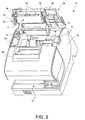
- is a perspective view of the printer with the cover open.
- Fig. 3
- is a perspective view showing the printer unit cover closed.
- Fig. 4
- is a perspective view showing the printer unit cover open.
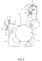
- Fig. 5
- is a side section view of the printer unit.
- Fig. 6
- is a side view of the printer unit when the cover is in the full open position.
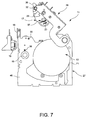
- Fig. 7
- is a side view of the printer unit when the cover is in the half open position.
- Fig. 8
- is a side view of the printer unit when the engagement levers contact the abutment.
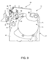
- Fig. 9
- is a side view of the printer unit when the platen starts to rotate away from the cover.
- Fig. 10
- is a side view of the printer unit just before the cover reaches the fully closed position.
- Fig. 11
- is a side view of the printer unit when the cover is in the fully closed position.
- Fig. 12
- is a perspective view of the diversion unit.
- Fig. 13
- is a perspective view of the entire printer unit showing the cover locking mechanism.
- Fig. 14
- is a perspective view of the cover locking mechanism from above.
- Fig. 15
- is a perspective view of the cover locking mechanism from below.
- Fig. 16
- is a side view of the cover locking mechanism when the cover is in the fully closed position.
- Fig. 17
- is a side view of the cover locking mechanism just after the cover release button is operated.
- Fig. 18
- is a side view of the cover locking mechanism at the start of the cover opening operation.
- Fig. 19 (A)
- is a side view showing the pivot part of the lock release lever, and Figs. 19(B), 19(C), and 19(D) are a plan view, a front view, and a side view, respectively, of the pivot part of the lock release lever support member.
- Fig. 20 to Fig. 23
- show the installation of the lock release lever.
- Fig. 24
- is a perspective view of the paper cutter mechanism.
- Fig. 25
- is a side view of the paper cutter mechanism.
- Fig. 26
- is a schematic side view showing the location of the first transportation roller pair in an alternative embodiment of the invention.
- As will be known from figures 1 to 5, the
printer 10 comprises aprinter unit 11 with a cover 12 (a housing member). Theprinter 10 has apaper storage unit 13 for storing a paper roll P1 (a continuous sheet medium), and aform insertion opening 14 for inserting a single-sheet form P2 (single sheet medium). The roll paper transportation path and the single-sheet transportation path are configured to transport roll paper, which is pulled out from the paper roll P1 instorage unit 13, and transport a single-sheet form P2, which inserted into theform insertion opening 14, to and past acommon printing position 15. - A
print head 16 and amovable platen 17, in its operating position, are disposed opposite each other and define theprinting position 15 between them. Downstream therefrom is disposed adiversion unit 18 for diverting the paper roll P1 and single-sheet form P2 to corresponding ejection paths. - The
print head 16 can be, for example, an inkjet print head mounted on a carriage (not shown in the figure) that travels bidirectionally widthwise to the paper transportation path for dot matrix printing on the surface of roll paper or single-sheet form P2 backed by theplaten 17. Roll paper pulled out from the paper roll P1 passes between a first fixed transportation roller 19 (drive roller) and first movable transportation roller 20 (pinch roller) to theprinting position 15, and passes between a second fixed transportation roller 21 (pinch roller ) and second movable transportation roller 22 (drive roller) and by a cutter mechanism 48 (further described below) behind thediversion unit 18 before being ejected fromroll paper exit 23. A single-sheet form P2 inserted into form insertion opening 14 passes between a pair of single-sheet transportation rollers 24 to theprinting position 15 on the downstream side ofrollers 24, and passes in front of thediversion unit 18 to exit from the single-sheet form exit 25. - An opening 26 (see Fig. 6) is formed above the
paper storage unit 13, and the paper roll P1 is replaced through thisopening 26. Theopening 26 is opened and closed by acover 28 hinged at the back of a unit frame 27 (a housing member) so as to rotate freely up and down about a pivot axis that extend substantially in parallel to axis of the paper roll P1 and the stroke of theprint head 16. Thecover 28 is supported to rotate freely up and down pivoting on burringparts 28a fit into pivot holes (not shown in the figure) in the side frames 46 of theunit frame 27. - A pair of right and left lock levers 29 is disposed freely rotatable back and forth on the
cover 28 about a pivot axis that extends in parallel to that of thecover 28. When thecover 28 is closed from the open position and reaches the closed position, the lock levers 29 engage lock pins 30 disposed on theunit frame 27 and thus automatically lock thecover 28 in its closed position. To open thecover 28 acover release button 31 further described below is operated to disengage the lock levers 29 and unlock thecover 28. - One end of the
platen 17 is pivotally supported at the free end part of thecover 28 by way ofplaten support shaft 32 that extends in parallel to the pivot axis of thecover 29. The firstmovable transportation roller 20 is disposed on aroller shaft 33 at the free end side of theplaten 17, and the secondmovable transportation roller 22 is disposed onplaten support shaft 32 at the fixed (supported) end side. Atransfer gear mechanism 34 is disposed at one side of theplaten 17. - The second
movable transportation roller 22, which is the drive roller, is linked to the transportation motor (not shown in the figure) throughtransfer gear mechanism 34 when thecover 28 is fully closed, and is thus rotationally driven by power from the transportation motor. - The
platen 17 is urged to the bottom side of thecover 28 by an elastic retraction mechanism 60 (see Fig. 15), i.e., a tension coil spring stretched between a side of theplaten 17 and the bottom side of thecover 28, so that when thecover 28 is open the urging force of theelastic retraction mechanism 60 holds theplaten 17 to the bottom of the cover 28 (in the inoperative position of the platen). Note the bottom of the cover is that part that faces thepaper storage unit 13 when the cover is closed. - An
abutment 35 for rotatingplaten 17 between it inoperative and operative positions in conjunction with the opening and closing motion of thecover 28 is disposed proximally above thediversion unit 18 on theunit frame 27 side. Theabutment 35 is engaged by the pair of right and left engagement levers 36 protruding at the fixed end side of theplaten 17 to swing theplaten 17 between its two positions relative to the cover. The basic operation ofplaten 17 is further described below with reference to Figs. 6 to 11. - Fig. 6 is a side view of the printer unit when the
cover 28 is in the full open position. As shown in Fig. 6, theplaten 17 is held in a position along the bottom of thecover 28 by the urging force of theelastic retraction mechanism 60 when thecover 28 is fully open and a wide space is open above thepaper storage unit 13. One side of the roll paper transportation path is opened by retracting theplaten 17, firstmovable transportation roller 20, and secondmovable transportation roller 22 in conjunction with thecover 28. When thecover 28 is thus open, paper roll P1 can be loaded into thepaper storage unit 13 and the end of the paper roll P1 can be fed into the roll paper transportation path from thepaper storage unit 13. - Fig. 7 is a side view of the printer unit when the cover is about half open, Fig. 8 is a side view of the printer unit when the engagement levers contact the abutment, Fig. 9 is a side view of the printer unit when the platen starts to rotate away from the
cover 28, and Fig. 10 is a side view of the printer unit just before the cover reaches the fully closed position. As will be known from these figures, when thecover 28 is closed after loading paper roll P1 into thepaper storage unit 13, the engagement levers 36 of theplaten 17 engageabutment 35. When thecover 28 is then pressed to the closed position, the engagement levers 36, which are restricted by theabutment 35 from moving further down, rotate clockwise relative to the cover 28 (as viewed in Fig. 8), causing theplaten 17 to rotate downward and forward away from the cover bottom and against the urging force of theelastic retraction mechanism 60. Theplaten 17 thus rotates downward and forward together withcover 28, and enters the space below thediversion unit 18. - Fig. 11 is a side view of the printer unit when the cover is in the fully closed position. As shown in Fig. 11 when the
cover 28 is closed to the position at which thecover 28 is automatically locked fully closed by the lock levers 29, theplaten 17 has reached its operative position opposite theprint head 16, firstmovable transportation roller 20 and secondmovable transportation roller 22 press the roll paper to the first fixedtransportation roller 19 and second fixedtransportation roller 21, respectively, and theprinter 10 is ready to print. - When the
cover 28 is thus fully closed and thecover release button 31 is operated, thecover 28 can be opened. When thecover 28 opens, action opposite that of the closing operation and the urging force of theelastic retraction mechanism 60 cause the engagement levers 36 to rotate relatively forward (i.e., counterclockwise as viewed in Fig.7 to 11), thus causing theplaten 17 to rotate toward its inoperative position at the bottom of thecover 28. Theplaten 17 thus rotates up and back in conjunction with the opening motion of thecover 28, and retracts from the space below thediversion unit 18. - Note that when the
cover 28 is being closed as described above, first the secondmovable transportation roller 22 contacts the second fixedtransportation roller 21 downstream fromprint head 16, and subsequently the firstmovable transportation roller 20 contacts the first fixedtransportation roller 19 upstream from theprint head 16. This applies appropriate tension to the roll paper pulled out from thepaper storage unit 13 through the paper roll transportation path. In addition, because of the offset in the timing at which the first and secondmovable transportation rollers movable transportation rollers - The
platen 17 haspositioning guide parts 37 on the free end side on both right and left side parts. Thepositioning guide parts 37 each have aguide channel 37a (see Fig. 6) with an opening to the bottom side, i.e., the side opposite to theplaten support shaft 32. Thepositioning guide parts 37 engage a respective guide pin 38 (fixed guide part) fixed on the corresponding unit frame side to precisely position theplaten 17 in its operative position. More specifically, as shown in Fig. 10, when thecover 28 is closed to the position just before the fully closed position, theabutment 35 substantially stops rotation of theplaten 17, and theplaten 17 descends substantially vertically with slight free rotation allowed. Aninclined guide surface 37b (see Fig. 6) formed on the bottom part ofpositioning guide part 37 contacts fixedguide pin 38 at this time, guiding the fixedguide pin 38 into theguide channel 37a and thus guiding theplaten 17 into position. This assures that theplaten 17, in its operative position, is positioned accurately relative to theprint head 16. More specifically, a specified gap is formed between the platen surface and the nozzle surface of the print head whereby theplaten 17 supports the paper relative to theprint head 16. Note that forming such gap is not essential to the present invention. If a thermal head is used asprint head 16, for instance, the guide channel 7a would have to be formed in a way so that the platen elastically presses the (thermal) paper against the print head. - The guiding direction (engaging direction) of the
guide channel 37a is substantially perpendicular to the direction in which theplaten 17 separates from theprint head 16, and is substantially perpendicular to a line tangent to the firstmovable transportation roller 20 and first fixedtransportation roller 19. - The
positioning guide parts 37 thus reliably limit the escape ofplaten 17 from theprint head 16, and also accurately position the firstmovable transportation roller 20 to the first fixedtransportation roller 19. - Fig. 12 is a perspective view of the diversion unit. As shown in Fig. 12, the
diversion unit 18 has adiverter plate 39 forming a single-sheet paper transportation path, asupport member 40, and a fixedknife 41. Thesupport member 40 is disposed on the back of thediverter plate 39 and freely rotatably axially supports the second fixedtransportation roller 21. The fixedknife 41 is disposed atsupport member 40 and is used to cut the ejected part of the roll paper. Thediversion unit 18 thus comprised is disposed to rotate freely back and forth on theunit frame 27 by way ofdiverter support shaft 42, and is urged to theplaten 17 side (secondmovable transportation roller 22 side) by apresser spring 43 disposed at both right and left ends of thediverter support shaft 42. More specifically, thediversion unit 18 is constructed so that it can retract to a position not interfering withcover 28 opening and closing operations, and to press the second fixedtransportation roller 21 to the secondmovable transportation roller 22 with the urging force of presser springs 43 when thecover 28 is in the closed position to assure reliable paper transportation. It should be noted that one end of the presser springs 43 is engaged in a channel on the respective side ofunit frame 27, and the other end is engaged byprotrusion 40a ofsupport member 40. - Fig. 24 is a perspective view and Fig. 25 is a side view of the paper cutter mechanism. As shown in these figures the
paper cutter mechanism 48 has the fixedknife 41 disposed side to side on thediversion unit 18, aguide shaft 49 disposed side to side at the end side of thecover 28, a movableknife support member 50 freely movable side to side along theguide shaft 49, a rotatingshaft 51 projecting downward from the front edge part of the movableknife support member 50, a rotary-typemovable knife 52 disposed integrally to the bottom end part of therotating shaft 51, and acam shaft 53 for reciprocally moving the movableknife support member 50 side to side. - The
cam shaft 53 is supported at the free end side of thecover 28 to rotate freely and has acam groove 53a formed in the outside surface thereof for producing a side to side movement. Thecam groove 53a is an endless groove having two spiral grooves winding in opposite directions and connecting channel parts linking the ends of the spiral grooves. Thecam groove 53a engages afollower member 54 freely rotatably coupled to the movableknife support member 50. This configuration causes the movableknife support member 50 andmovable knife 52 to move reciprocally along the fixedknife 41 while thecam shaft 53 rotates in one direction. Drive power from the transportation motor is transferred to thecam shaft 53 via acam shaft gear 57 disposed at the left end part of thecam shaft 53. - As shown in Fig. 25, a
paper guide 55 is disposed from side to side between therotating shaft 51 and the roll paper transportation path. Thispaper guide 55 functions as an exit guide for the roll paper and has a fixedrack 55a formed integrally to the back thereof from side to side. - A
gear 56 for rotating the movable knife is disposed integrally to therotating shaft 51, and meshes with fixedrack 55a so that as the movableknife support member 50 moves themovable knife 52 is turned in an appropriate direction (the direction in which the edge of themovable knife 52 rotates toward the fixed knife 41). - It is therefore possible to rotate the
movable knife 52 in the appropriate direction without disposing in intermediate gear between the fixedrack 55a andknife gear 56. When seen from the side, the rotatingshaft 51 is positioned at an angle to the roll paper transportation path so that the down side (themovable knife 52 side) approaches the roll paper transportation path and the top side (the knife gear side) recedes from the roll paper transportation path. It is therefore possible to assure space for the fixedrack 55a (paper guide 55) between the roll paper transportation path andknife gear 56 while reducing the size of themovable knife 52. - Fig. 13 is a perspective view of the entire printer unit showing the cover locking mechanism, Fig. 14 is a perspective view of the cover locking mechanism as seen from above, and Fig. 15 is a perspective view of the cover locking mechanism as seen from below. As shown in these figures, the
cover locking mechanism 44 includes the above-described lock levers 29 disposed on the cover side, the lock pins 30 disposed on the unit frame side, and alock release lever 45 for moving the lock levers 29 to the lock release side (unlocked position) according to the operation of thecover release button 31. - The lock levers 29 each have a
hook part 29a (see also Fig. 16) for engaging thelock pin 30, and aninclined guide part 29b (see also Fig. 16) for automatically engaging thelock pin 30. The lock levers 29 are disposed on right and left sides at the free end side of thecover 28. The base end parts of the pair of lock levers 29 are integrally linked by an intervening pipe-like connectingrod 29c, are supported so as to pivot freely back and forth on alever support shaft 29d fit to connectingrod 29c, and are urged by a restoringspring 29e in the lock pin engaging direction. The lock pins 30 project to the inside part of theside frame 46, and engage the lock levers 29 to hold thecover 28 in the closed position. - The
lock release lever 45 has afirst lever part 45a linked to thecover release button 31, asecond lever part 45b linked to the lock levers 29 anddiversion unit 18, and a connectingpart 45c integrally connecting the top end parts of bothlever parts first lever part 45a has abutton engaging part 45d for engaging the cover release button 31 (see Fig. 16), and apivot hole 45e that is fit to rotation supportpart 47a of the lock releaselever support member 47 further described below. Thefirst lever part 45a is thus supported so that it pivots freely back and forth onpivot hole 45e. Thesecond lever part 45b has a locklever engaging part 45f for engaging the engagingtab 29f of the rightside lock lever 29, adiverter engaging part 45g for engagingprotrusion 40a ofdiversion unit 18, and a burringpart 45h that is fit into a pivot hole (not shown in the figure) in theside frame 46. Thesecond lever part 45b is thus supported to pivot freely back and forth on the burringpart 45h. - The
cover release button 31 is affixed to theunit frame 27 so that the button can slide freely in a linear direction, and in this preferred embodiment of the invention is operated to be pushed straight down. - Fig. 16 is a side view of the cover locking mechanism when the cover is in the fully closed position. When the
cover 28 is completely closed as shown in Fig. 16, lock levers 29 engage lock pins 30 and hold thecover 28 closed. The urging force ofpresser spring 43 also causes thediversion unit 18 to press second fixedtransportation roller 21 to secondmovable transportation roller 22. - Fig. 17 is a side view of the cover locking mechanism just after the
cover release button 31 is operated, and Fig. 18 is a side view of the cover locking mechanism at the start of the cover opening operation. As indicated in these figures, when thecover release button 31 is pushed in a straight line while thecover 28 is in the fully closed position, the operating force of the button rotates thelock release lever 45 forward. When thelock release lever 45 rotates forward the locklever engaging part 45f ofsecond lever part 45b pushes the engagingtab 29f of lock levers 29 forward, causing the lock levers 29 to move to the lock releasing side and thereby allowing thecover 28 to open. Simultaneously thereto thediverter engaging part 45g ofsecond lever part 45b pushesprotrusion 40a ofdiversion unit 18 forward. Thediversion unit 18 therefore retracts automatically to a position not interfering with opening and closingcover 28, and thecover 28 can open smoothly. - Fig. 19 (A) is a side view showing the pivot part of the
lock release lever 45, and Figs. 19 (B), 19 (C), and 19 (D) are a plan view, front view, and side view, respectively, of the pivot part of the lock releaselever support member 47. As shown in these figures a notchedpart 45i open to the bottom and contiguous to thepivot hole 45e is formed in thefirst lever part 45a oflock release lever 45. The lock releaselever support member 47 is a resin molding having rotation supportpart 47a integrally disposed to the right top part thereof. Therotation support part 47a has a flatnarrow part 47b to which the notchedpart 45i oflock release lever 45 is fit from above, and apivot shaft part 47c projecting to the right side fromnarrow part 47b. When the notchedpart 45i is fit to thenarrow part 47b,pivot hole 45e can be fit to thepivot shaft part 47c so that thefirst lever part 45a oflock release lever 45 is pivotally supported by thepivot shaft part 47c. - The structure for installing the lock release lever is described next below with reference to Figs. 20 to 23. As shown in Fig. 20, the
lock release lever 45 is first tilted forward (outside the normal range of rotation) and the notchedpart 45i offirst lever part 45a is fit down onto thenarrow part 47b of lock release lever support member 47 (see arrow (1) in Fig. 20). Thelock release lever 45 is then slid to the right as seen in the figures to fit thepivot hole 45e infirst lever part 45a to thepivot shaft part 47c of lock releaselever support member 47, and fit the burringpart 45h ofsecond lever part 45b into the pivot hole in the side frame 46 (see arrow (2) in Fig. 20). Next, thelock release lever 45 is rotated into the normal range of rotation and theengaging abutment 45j formed on the left end part of thelock release lever 45 is engaged with thestopper 46a formed on side frame 46 (see arrow (3) in Fig. 22). Sideways movement of thelock release lever 45 is thus limited by thesecond lever part 45b contacting the left side of theside frame 46 and theengaging abutment 45j engaging thestopper 46a from the right side. Thecover release button 31 is then installed to theunit frame 27 so that it can slide freely up and down (see (4) in Fig. 23). Rotation of thelock release lever 45 beyond the normal range of rotation is thus limited by thecover release button 31. - An alternative configuration of the
platen 17 positioning construction is described next. It should be noted that elements having the same function in the configuration described above are identified by like reference numerals and further description thereof is omitted below. - Fig. 26 is a schematic side view showing the location of the first transportation roller pair. As shown in the figure, this alternative embodiment transports roll paper by means of first
transportation roller pair print head 16 without providing the secondtransportation roller pair print head 16. As seen in this side view, theroller shaft 33 of firstmovable transportation roller 20 is disposed on the print head side of an imaginary line A passing through the center of the pivot axis of platen 17 (platen support shaft 32) and the center of first fixedtransportation roller 19. In other words, roller tangent B tangent to firsttransportation roller pair print head 16, thus limiting movement of firstmovable transportation roller 20 away from theprint head 16 and applying pressure pushing the firstmovable transportation roller 20 forward towards theprint head 16. Theplaten 17 can thus be positioned using the firsttransportation roller pair platen 17 andprint head 16. When theroller shaft 33 is positioned as described above the firstmovable transportation roller 20 must be able to travel over the first fixedtransportation roller 19 when thecover 28 is opened and closed. Theroller shaft 33 is therefore supported inelliptical holes 17a (accommodating means) so that it can move freely up and down relative to theplaten 17, and is urged downwardly by an elastic mechanism not shown in the figures. - As will be known from the above, a
printer 10 according to a preferred embodiment of the invention has a housing (includingcover 12 and unit frame 27) with apaper storage unit 13 for holding paper roll P1, acover 28 for opening and closing anopening 26 topaper storage unit 13, aprint head 16 for printing on roll paper pulled off the paper roll P1 in thepaper storage unit 13, aplaten 17 disposed to rotate freely on thecover 28 for guiding the back of the paper roll P1 to a proximal position opposite theprint head 16, and anabutment 35 for engaging the engagement levers 36 of theplaten 17 and rotating theplaten 17 in a contrary direction in conjunction with opening and closing thecover 28. It is therefore possible to retract theplaten 17 together with thecover 28 without interfering with other internal parts of theprinter 10 when thecover 28 is opened, and unlike a conventional sliding mechanism used to advance and retract the platen, the configuration of the present invention does not interfere with smooth opening and closing of thecover 28, invite an increase in printer size, or require much space around the printer. - Furthermore, by providing a first
movable transportation roller 20 disposed to the free end side of theplaten 17 for transporting the roll paper between the first movable transportation roller and a first fixedtransportation roller 19 disposed inside the printer, the roll paper can be easily aligned to the paper transportation path when thecover 28 is closed. - Yet further, by further providing a second
movable transportation roller 22 disposed at the fixed end side of theplaten 17 for transporting the roll paper between the second movable transportation roller and a second fixedtransportation roller 21 disposed inside the printer, roll paper transportation problems can be prevented by transporting the paper with a pair of first and second transportation rollers. In addition, by holding the roll paper with the first and secondmovable transportation rollers cover 28 is closed, appropriate tension can be applied to the roll paper and printing defects caused by slack in the roll paper can be prevented. - Furthermore, because the first
movable transportation roller 20 contacts the first fixedtransportation roller 19 on the upstream side of theprint head 16 after the secondmovable transportation roller 22 contacts the second fixedtransportation roller 21 on the downstream side of theprint head 16 when thecover 28 is operated to close, problems such as excessive force acting on the roll paper and thetransportation rollers - Further preferably, a
positioning guide part 37 is disposed on the free end side of theplaten 17 for guiding theplaten 17 into position when thecover 28 is operated to close. This accurately positions theplaten 17 and thus prevents printing defects and transportation problems. - Yet further preferably, the
abutment 35 substantially stops rotation of theplaten 17 near the fully closed position of thecover 28, and engages thepositioning guide part 37 with a fixedguide pin 38 on the housing side. Theplaten 17 can thus be positioned accurately. - The guiding direction of the
positioning guide part 37 is substantially perpendicular to the direction in which theplaten 17 escapes from theprint head 16. Movement of theplaten 17 away from theprint head 16 is thus reliably restricted by thepositioning guide parts 37, and printing defects caused by theplaten 17 separating from theprint head 16 can be prevented. - Furthermore, because the guiding direction of the
positioning guide part 37 is substantially perpendicular to a tangent of the firstmovable transportation roller 20 and the first fixedtransportation roller 19, the firstmovable transportation roller 20 can be accurately positioned with respect to the first fixedtransportation roller 19, and paper transportation problems due to an offset in the positions of thetransportation rollers - Yet further preferably, a first
movable transportation roller 20 is disposed on the free end side of theplaten 17 for transporting the roll paper between the firstmovable transportation roller 20 and the first fixedtransportation roller 19 disposed inside the printer. The support axis (shaft) 33 of the first movable transportation roller is positioned on the print head side of an imaginary line passing through the center of rotation of the platen and the center of rotation of the first fixed transportation roller rotation as seen in a side view. It is therefore possible to press and position theplaten 17 to theprint head 16 using the first fixedtransportation roller 19 and firstmovable transportation roller 20. The number of parts can therefore be reduced and the structure simplified compared with a configuration using special platen presser or platen positioning members. - Yet further preferably,
elliptical holes 17a (accommodating means) allowing the firstmovable transportation roller 20 to pass over the first fixedtransportation roller 19 in conjunction with opening and closing thecover 28 are provided. This reduces the load of the firstmovable transportation roller 20 as it moves over the first fixedtransportation roller 19, thus avoids deformation of or damage to members when the movable transportation roller rides over the fixed transportation roller, and avoids problems interfering with smooth opening and closing of thecover 28. - The
print head 16 can print on roll paper (continuous sheet medium) and single-sheet forms P2 (single sheet medium), and the printer additionally has adiversion unit 18 disposed downstream from the print head on the frame side for diverting the roll paper and single-sheet form P2 to respective paths. Thediversion unit 18 can be retracted to a position not interfering with opening and closing the cover. In other words, while thediversion unit 18 for diverting the paper roll P1 and single-sheet form P2 to separate exit paths is disposed downstream of theprint head 16, thediversion unit 18 can be automatically retracted when thecover 28 is opened or closed to a position not interfering with opening and closing thecover 28. Interference between thediversion unit 18 andplaten 17 is therefore reliably avoided, thecover 28 can be smoothly opened, and damage to thediversion unit 18 can be avoided. - Yet further preferably the abutment is positioned near the
diversion unit 18. In other words, by disposing theabutment 35 near thediversion unit 18, which is prevented from interfering with theplaten 17, theplaten 17 can be made as small as possible and theabutment 35 is prevented from interfering with replacing the paper roll P1. - Furthermore, by disposing the second fixed
transportation roller 22 to thediversion unit 18 and transporting the roll paper on the downstream side of theprint head 16, slack can be prevented in the roll paper, and the paper can be reliably transported passed the diversion unit. In addition, because thediversion unit 18 is also used as the support member for the second fixedtransportation roller 21, the part count can be reduced and the structure can be simplified. - Furthermore, the
diversion unit 18 is configured to rotate freely in an advancing-retracting direction relative to the roll paper (continuous sheet medium) transportation path or secondmovable transportation roller 22, and is urged by apresser spring 43 in the advancing direction. Thediversion unit 18 can therefore be smoothly retracted when there is contact with theplaten 17, and pressure can be applied reliably to the paper due to the urging force of thepresser spring 43. - Yet further, because the
diversion unit 18 has a fixedknife 41 for cutting the roll paper, thediversion unit 18 is also used as the support member for the fixedknife 41. This further reduces the part count and simplifies the structure. - Further preferably, the printer has a
cover release button 31 disposed on the frame side and operated in a straight line, and acover locking mechanism 44 for locking the cover in a closed position. Thecover locking mechanism 44 enables the cover to be opened when the cover release button is operated, and thus enables thediversion unit 18 to move to the retracted side. - The
cover locking mechanism 44 has lock pins 30 disposed on the frame side; locklevers 29 rotatably disposed at the frame side for engaging and releasing the lock pins 30; and alock release lever 45 rotatably disposed at the frame side. When thecover release button 31 is operated thelock release lever 45 moves the lock levers 29 to disengage and release the lock pins, and move thediversion unit 18 to the retracted side. That is, while thecover release button 31 travels in a straight line it moves the lock levers 29 anddiversion unit 18 by way of a pivotinglock release lever 45, thereby reducing the force needed to operate thecover release button 31 and further improving the operability of the cover opening operation. - Yet further preferably, the
lock release lever 45 has afirst lever part 45a linked to thecover release button 31; asecond lever part 45b linked to the lock levers 29 and thediversion unit 18; and a connectingpart 45c integrally linking the first andsecond lever parts second lever parts lock release lever 45 strength, enables thelock release lever 45 to operate smoothly, and thus further improves the operability of the cover opening operation. - Yet further preferably, a lock release lever support part (lock release
lever support member 47 and side frame 46) supporting thelock release lever 45 to pivot freely comprises arotation support part 47a enabling attaching thelock release lever 45 from a lateral direction outside the normal rotation range; and astop part 46a limiting lateral movement of thelock release lever 45 in the normal rotation range. Rotation of thelock release lever 45 to outside the normal rotation range is limited by thecover release button 31. A special member for limiting lateral movement of thelock release lever 45 is thus unnecessary, and the part count and the number of assembly steps reduced can therefore be reduced and the structure can be simplified. - Further preferably, the
first lever part 45a has a notchedpart 45i contiguous to thepivot hole 45e, and therotation support part 47a has anarrow part 47b to which the notchedpart 45i fits and apivot shaft part 47c protruding horizontally from thenarrow part 47b. Thepivot hole 45e can be fit to thepivot shaft part 47c when the notchedpart 45i is fit to thenarrow part 47b. It is therefore possible to mount thelock release lever 45 to therotation support part 47a using a simple configuration having a notchedpart 45i formed in thelock release lever 45 and anarrow part 47b formed to therotation support part 47a. - A preferred embodiment of the present invention has been described above with reference to the accompanying figures, and it will be apparent to one with ordinary skill in the art that the invention can be varied in many ways without departing from the scope of the accompanying claims.
- For example, an
engagement lever 36 andabutment 35 engaging theengagement lever 36 are disposed on both side ends in the above embodiment, but could be disposed on only one end. Furthermore, thediverter support shaft 42 or thepresser spring 43 coupled to thediverter support shaft 42 could alternatively be used as theabutment 35. - Furthermore, the fixed transportation roller is described above as being on the drive side and the movable transportation roller as being on the driven (follower) side, but these could be reversed so that the fixed transportation roller is the driven (follower) side and the movable transportation roller is the drive side.
- A printer according to the present invention can retract the platen and transportation rollers while avoiding interference with internal printer parts when opening the cover, does not obstruct smooth opening and closing of the cover, does not invite an increase in printer size, does not require a wide space around the printer, and can accurately position the platen to prevent print defects and paper transportation problems.
- Furthermore, while the printer has a diversion unit at a position downstream of the print head for diverting continuous sheet media and single sheet media, the diversion unit is automatically retracted to a position where the diversion unit will not interfere with opening and closing the cover when the cover is opened. The cover can therefore be smoothly opened and closed, and damage to the diversion unit can be prevented. The operability of the cover opening operation is also improved by releasing the cover lock and retracting the diversion unit as a result of a linear operation of the cover release button.
Claims (20)
- A printer comprising:a frame having a storage unit (13) for storing a continuous sheet medium;a cover (28) for opening and closing an opening (26) to the storage unit (13);a print head (16) for printing on the continuous sheet medium pulled from the storage unit (13);a platen (17) pivotally supported on the cover (28) and movable between an inoperative and an operative position relative to the cover (28) for guiding, in its operative position, a back surface of the continuous sheet medium at a position opposite the print head (16); andan abutment (35) for engaging a fixed end side of the platen (17) and rotating the free end side of the platen (17) in conjunction with opening and closing of the cover (28), the platen (17) retracting from its operative position in conjunction with a cover opening operation, and advancing to the operative position in conjunction with a cover closing operation.
- A printer as described in claim 1, further comprising a first movable transportation roller (20) disposed at the free end side of the platen (17) for transporting the continuous sheet medium between the first movable transportation roller (20) and a first fixed transportation roller (19) on the frame side.
- A printer as described in claim 2, further comprising a second movable transportation roller (22) disposed at the fixed end side of the platen (17) for transporting the continuous sheet medium between the second movable transportation roller (22) and a second fixed transportation roller (21) disposed on the frame side.
- A printer as described in claim 3, wherein the first movable transportation roller (20) contacts the first fixed transportation roller (19) on an upstream side of the print head (16) after the second movable transportation roller (22) contacts the second fixed transportation roller (21) on a downstream side of the print head (16) when the cover (28) is operated to close.
- A printer as described in any one of claims 1 to 4, further comprising a positioning guide part (37) disposed on the free end side of the platen (17) for positioning and guiding the platen (17) relative to the frame when the cover (28) is operated to close.
- A printer as described in claim 5, wherein the abutment (35) substantially stops rotation of the platen (17) near the fully closed position of the cover (28), so as to allow the positioning guide part (37) engage with a fixed guide part (38) on the frame side.
- A printer as described in claim 5 or 6, wherein the guiding direction of the positioning guide part (37) is substantially perpendicular to the direction in which the platen (17) escapes from the print head (16) when the cover (28) is opened.
- A printer as described in any one of claims 5 to 7, wherein the guiding direction of the positioning guide part (37) is substantially perpendicular to a tangential direction of the first movable transportation roller (20) and the first fixed transportation roller (19).
- A printer as described in claim 1, further comprising a first movable transportation roller (20) disposed on the free end side of the platen (17) for transporting the continuous sheet medium between the first movable transportation roller (20) and a first fixed transportation roller (19) disposed on the frame side, the support axis of the first movable transportation roller (20) being positioned toward the print head (16) from an imaginary line passing through a rotational center of the platen (17) and rotational center of the first fixed transportation roller (19).
- A printer as described in claim 9, further comprising an accommodating means (17a) for allowing the first movable transportation roller (20) to pass over the first fixed transportation roller (19) in conjunction with opening and closing the cover (28).
- A printer as described in any one of claims 1 to 10, wherein the print head (16) can print to said continuous sheet medium and a single sheet medium (P2), the printer further comprising a diversion unit (18) disposed at a position downstream of the print head (16) on the frame side, the diversion unit (18) routing the continuous sheet medium and single sheet medium and being retractable to a position not interfering with the opening and closing of the cover (28).
- A printer as described in claim 11, wherein the abutment (35) is positioned near the diversion unit (18).
- A printer as described in claim 11 or 12, wherein the second fixed transportation roller (21) is coupled to the diversion unit (18).
- A printer as described in any one of claims 11 to 13, wherein the diversion unit (18) is configured to rotate freely in an advancing-retracting direction relative to the continuous sheet medium transportation path or second movable transportation roller (22), and is urged by a presser spring (43) in the advancing direction.
- A printer as described in claim 11, wherein the diversion unit (18) comprises a fixed knife (41) for cutting the continuous sheet medium.
- A printer as described in claim 11, further comprising a cover release button (31) disposed on the frame side and operated in a linear direction; and
a cover locking mechanism for locking the cover (28) in a closed position, enabling a cover opening operation and moving the diversion unit (18) to the retracted side in conjunction with operation of the cover release button (31). - A printer as described in claim 16, wherein the cover locking mechanism comprises:a lock pin (30) disposed on the frame side;a lock lever (29) rotatably coupled to the frame side for engaging and releasing the lock pin (30); anda lock release lever (45) rotatably coupled to the frame side for operating the lock lever (29) to a release lock side and operating the diversion unit (18) to the retracted side in conjunction with operation of the cover release button.
- A printer as described in claim 17, wherein the lock release lever (45) comprises a first lever part (45a) engageable by the cover release button;
a second lever part (45b) adapted to engage the lock lever (29) and the diversion unit (18); and
a connecting part (45c) integrally linking the first and second lever parts, the first and second lever parts being rotatably supported. - A printer as described in claim 17 or 18, wherein a lock release lever support part (47) freely rotatably supporting the lock release lever (45) comprises:a rotation support part (47a) enabling attaching the lock release lever (45) from a lateral direction outside the normal rotation range; anda stop part (45j) limiting lateral movement of the lock release lever (45) in the normal rotation range; whereinrotation of the lock release lever (45) to outside the normal rotation range is limited by the cover release button (31).
- A printer as described in claim 18 or 19, wherein the first or second lever part (45a, 45b) comprises a notch part (45i) communicating with a pivot hole (45e);
the rotation support part (47a) comprising a narrow part (47b) to which the notch part can be fit; and
a pivot shaft part (47c) protruding laterally from the narrow part and permitting fitting with the pivot hole (45e) when the notch part is fit to the narrow part.
Applications Claiming Priority (6)
| Application Number | Priority Date | Filing Date | Title |
|---|---|---|---|
| JP2001191871 | 2001-06-25 | ||
| JP2001191871A JP3741003B2 (en) | 2001-06-25 | 2001-06-25 | Printer |
| JP2001191875A JP3785955B2 (en) | 2001-06-25 | 2001-06-25 | Printer |
| JP2001191875 | 2001-06-25 | ||
| JP2001318595 | 2001-10-16 | ||
| JP2001318595A JP3680781B2 (en) | 2001-10-16 | 2001-10-16 | Printer |
Publications (3)
| Publication Number | Publication Date |
|---|---|
| EP1270242A2 true EP1270242A2 (en) | 2003-01-02 |
| EP1270242A3 EP1270242A3 (en) | 2003-10-01 |
| EP1270242B1 EP1270242B1 (en) | 2006-05-24 |
Family
ID=27347018
Family Applications (1)
| Application Number | Title | Priority Date | Filing Date |
|---|---|---|---|
| EP02013591A Expired - Lifetime EP1270242B1 (en) | 2001-06-25 | 2002-06-20 | Printer |
Country Status (8)
| Country | Link |
|---|---|
| US (1) | US6789969B2 (en) |
| EP (1) | EP1270242B1 (en) |
| KR (1) | KR100431388B1 (en) |
| CN (1) | CN1181979C (en) |
| AT (1) | ATE327105T1 (en) |
| DE (1) | DE60211596T2 (en) |
| ES (1) | ES2260356T3 (en) |
| HK (1) | HK1052903B (en) |
Cited By (5)
| Publication number | Priority date | Publication date | Assignee | Title |
|---|---|---|---|---|
| EP1455515A1 (en) * | 2003-03-07 | 2004-09-08 | Sagem SA | Fax machine with a housing having two half-shells |
| EP1595710A2 (en) * | 2004-04-20 | 2005-11-16 | Star Micronics Co., Ltd. | Printer with movable paper guiding element |
| EP1586455A3 (en) * | 2004-04-16 | 2006-11-15 | Bixolon Co., Ltd. | Printer with pivotable platen |
| EP3042779A1 (en) * | 2014-12-22 | 2016-07-13 | Seiko Epson Corporation | Printer |
| EP3184316A4 (en) * | 2015-01-06 | 2018-04-11 | Seiko Epson Corporation | Printing device |
Families Citing this family (32)
| Publication number | Priority date | Publication date | Assignee | Title |
|---|---|---|---|---|
| JP4072409B2 (en) * | 2002-09-24 | 2008-04-09 | キヤノン株式会社 | Image reading apparatus and image forming apparatus having the same |
| CN1302936C (en) * | 2003-05-02 | 2007-03-07 | 精工爱普生株式会社 | Printer |
| JP4389534B2 (en) * | 2003-09-25 | 2009-12-24 | セイコーエプソン株式会社 | Open / close lid lock / unlock mechanism and printer |
| JP4107261B2 (en) * | 2003-11-14 | 2008-06-25 | セイコーエプソン株式会社 | Printer with cutter mechanism |
| ITTO20030909A1 (en) * | 2003-11-17 | 2005-05-18 | Olivetti Tecnost S P A Ora Olivett I Spa | DEVICE FOR PRINTING RECEIPTS USING TWO PRINTING UNITS, IN PARTICULAR ON THERMAL PAPER, AND ITS PRINTING METHOD. |
| JP4517743B2 (en) * | 2004-06-23 | 2010-08-04 | セイコーエプソン株式会社 | Printing unit |
| TWI279322B (en) * | 2004-06-23 | 2007-04-21 | Seiko Epson Corp | Printing unit |
| JP4581677B2 (en) * | 2004-12-27 | 2010-11-17 | セイコーエプソン株式会社 | Printer with peeler function |
| US7505058B2 (en) * | 2005-12-07 | 2009-03-17 | Dell Product L.P. | Single head receipt printer |
| US7878724B2 (en) * | 2005-12-27 | 2011-02-01 | Seiko Epson Corporation | Printer |
| US7914218B2 (en) | 2006-06-29 | 2011-03-29 | Toshiba Tec Kabushiki Kaisha | Thermal printer and printing device |
| US7785025B2 (en) * | 2007-08-30 | 2010-08-31 | International Business Machines Corporation | Point of sale printer including an automated cover opening apparatus |
| JP5082749B2 (en) * | 2007-10-15 | 2012-11-28 | セイコーエプソン株式会社 | Printer |
| US7905670B2 (en) * | 2007-10-29 | 2011-03-15 | International Business Machines Corporation | Method and apparatus for exposing printable media in a printer |
| JP5109616B2 (en) * | 2007-11-20 | 2012-12-26 | セイコーエプソン株式会社 | Printer |
| EP2085238A1 (en) * | 2008-01-29 | 2009-08-05 | Custom Engineering SpA | Printing roll release of the head in the thermal printer |
| JP5445028B2 (en) * | 2009-10-23 | 2014-03-19 | セイコーエプソン株式会社 | Platen support mechanism and roll paper printer |
| JP2011178144A (en) * | 2010-03-04 | 2011-09-15 | Seiko Epson Corp | Gap control method of medium processor, and medium processor |
| US9434191B2 (en) | 2010-04-12 | 2016-09-06 | Zih Corp. | Label peeling, universal printheads and related methods |
| US9287724B2 (en) | 2010-04-12 | 2016-03-15 | Zih Corp. | Printer mobility and scalability |
| CN102241202B (en) * | 2010-05-14 | 2013-04-24 | 山东新北洋信息技术股份有限公司 | Printer |
| CN102241205B (en) * | 2010-05-14 | 2013-04-24 | 山东新北洋信息技术股份有限公司 | Printing device |
| KR101429565B1 (en) * | 2010-11-15 | 2014-08-12 | 제트아이에이치 코포레이션 | Media processing device and associated system |
| TWI471229B (en) * | 2012-01-05 | 2015-02-01 | Hiti Digital Inc | Fixing mechanism capable of fixing a thermal print head module in different positions and thermal sublimation printer therewith |
| JP6313548B2 (en) * | 2013-06-28 | 2018-04-18 | セイコーインスツル株式会社 | Thermal printer |
| CN106660381B (en) * | 2014-07-23 | 2019-04-30 | 富士通电子零件有限公司 | Print apparatus |
| WO2017020179A1 (en) * | 2015-07-31 | 2017-02-09 | Hewlett-Packard Development Company, L.P. | Stalling operation of imaging devices |
| CN105015196A (en) * | 2015-07-31 | 2015-11-04 | 苏州佳世达光电有限公司 | Printer |
| JP2019136919A (en) * | 2018-02-08 | 2019-08-22 | 東芝テック株式会社 | Printer |
| JP7334488B2 (en) * | 2019-06-12 | 2023-08-29 | ブラザー工業株式会社 | printer |
| KR102575128B1 (en) | 2020-11-24 | 2023-09-06 | 동의대학교 산학협력단 | Manufacturing of carbon heating element coated with thermal diffusion coating and method for improving flexibility and temperature non-uniformity |
| JP2022104152A (en) * | 2020-12-28 | 2022-07-08 | ブラザー工業株式会社 | Printer |
Citations (1)
| Publication number | Priority date | Publication date | Assignee | Title |
|---|---|---|---|---|
| JP2000118064A (en) | 1998-10-12 | 2000-04-25 | Seiko Epson Corp | Printer for rolled paper |
Family Cites Families (26)
| Publication number | Priority date | Publication date | Assignee | Title |
|---|---|---|---|---|
| US4330299A (en) | 1981-03-09 | 1982-05-18 | Evreka, Inc. | Article and method for measuring glucose level in body fluids |
| DE3583378D1 (en) | 1984-10-02 | 1991-08-08 | Fujitsu Ltd | PRINTER WITH A PAPER FEED INSERTIBLE FROM THE FRONT. |
| DE3661345D1 (en) | 1985-01-25 | 1989-01-12 | Siemens Ag | Document-processing device for forms obtained from an endless fan-fold web |
| JPH0679855B2 (en) * | 1986-10-15 | 1994-10-12 | 株式会社セコニツク | Recording device |
| JP2537904B2 (en) | 1987-10-09 | 1996-09-25 | 松下電器産業株式会社 | Thermal recording device |
| JPH01160663A (en) | 1987-12-18 | 1989-06-23 | Tokyo Electric Co Ltd | Recording device |
| US5219236A (en) | 1988-03-11 | 1993-06-15 | Brother Kogyo Kabushiki Kaisha | Recording apparatus capable of recording information on both a continuous recording medium and a cut-sheet recording medium |
| KR0133931B1 (en) | 1988-11-30 | 1998-04-20 | 오가 노리오 | Printer |
| JPH03258575A (en) | 1990-03-08 | 1991-11-18 | Mitsubishi Electric Corp | Printer device |
| JP2562709B2 (en) | 1990-03-27 | 1996-12-11 | 株式会社田村電機製作所 | Print head holding structure |
| JP2837251B2 (en) | 1990-09-11 | 1998-12-14 | 三菱化学株式会社 | Method for producing aromatic sulfone oligomer |
| JPH05147291A (en) | 1991-11-28 | 1993-06-15 | Sony Corp | Printer |
| US5528278A (en) | 1991-11-28 | 1996-06-18 | Sony Corporation | Video printer having rewind function to improve transfer sheet utilization |
| FR2697776B1 (en) | 1992-11-06 | 1995-03-03 | Axiohm | Opening thermal printing device. |
| US5631690A (en) | 1994-02-03 | 1997-05-20 | Seikosha Precision Inc. | Recording apparatus |
| US5516219A (en) | 1994-08-01 | 1996-05-14 | Lasermaster Corporation | High resolution combination donor/direct thermal printer |
| JPH08142445A (en) | 1994-11-21 | 1996-06-04 | Casio Electron Mfg Co Ltd | Image forming apparatus |
| JP3545830B2 (en) | 1995-04-27 | 2004-07-21 | 東芝テック株式会社 | Label printer |
| DE69607292T2 (en) | 1995-11-21 | 2000-08-31 | Seiko Epson Corp | Printer with cutting and protection device |
| DE69824943T2 (en) | 1997-04-02 | 2005-07-14 | Seiko Epson Corp. | PAPER ROLL LOADING MECHANISM FOR PRINTERS |
| US5887999A (en) | 1997-10-06 | 1999-03-30 | Axiohm Ipb Inc. | Paper loading mechanism |
| US5993093A (en) | 1997-11-04 | 1999-11-30 | Schoennauer; Larry Joseph | Printer |
| US6102590A (en) * | 1998-03-12 | 2000-08-15 | International Business Machines Corporation | Cover-platen opening mechanism |
| DE69922757T2 (en) * | 1998-10-02 | 2005-12-15 | Seiko Epson Corp. | Printer and method for its control |
| JP3614314B2 (en) | 1999-03-25 | 2005-01-26 | セイコーエプソン株式会社 | Printer |
| EP1108556B1 (en) * | 1999-12-15 | 2003-04-16 | Seiko Epson Corporation | Printer |
-
2002
- 2002-06-20 ES ES02013591T patent/ES2260356T3/en not_active Expired - Lifetime
- 2002-06-20 AT AT02013591T patent/ATE327105T1/en not_active IP Right Cessation
- 2002-06-20 EP EP02013591A patent/EP1270242B1/en not_active Expired - Lifetime
- 2002-06-20 DE DE60211596T patent/DE60211596T2/en not_active Expired - Lifetime
- 2002-06-21 US US10/178,446 patent/US6789969B2/en not_active Expired - Lifetime
- 2002-06-24 KR KR10-2002-0035327A patent/KR100431388B1/en active IP Right Grant
- 2002-06-24 CN CNB021248990A patent/CN1181979C/en not_active Expired - Lifetime
-
2003
- 2003-07-21 HK HK03105243.1A patent/HK1052903B/en not_active IP Right Cessation
Patent Citations (1)
| Publication number | Priority date | Publication date | Assignee | Title |
|---|---|---|---|---|
| JP2000118064A (en) | 1998-10-12 | 2000-04-25 | Seiko Epson Corp | Printer for rolled paper |
Cited By (9)
| Publication number | Priority date | Publication date | Assignee | Title |
|---|---|---|---|---|
| EP1455515A1 (en) * | 2003-03-07 | 2004-09-08 | Sagem SA | Fax machine with a housing having two half-shells |
| EP1586455A3 (en) * | 2004-04-16 | 2006-11-15 | Bixolon Co., Ltd. | Printer with pivotable platen |
| EP1595710A2 (en) * | 2004-04-20 | 2005-11-16 | Star Micronics Co., Ltd. | Printer with movable paper guiding element |
| EP1595710A3 (en) * | 2004-04-20 | 2006-06-21 | Star Micronics Co., Ltd. | Printer with movable paper guiding element |
| US7404683B2 (en) | 2004-04-20 | 2008-07-29 | Star Micronics Co., Ltd. | Printer |
| EP3042779A1 (en) * | 2014-12-22 | 2016-07-13 | Seiko Epson Corporation | Printer |
| US9855773B2 (en) | 2014-12-22 | 2018-01-02 | Seiko Epson Corporation | Printer |
| EP3184316A4 (en) * | 2015-01-06 | 2018-04-11 | Seiko Epson Corporation | Printing device |
| US10150309B2 (en) | 2015-01-06 | 2018-12-11 | Seiko Epson Corporation | Printing device |
Also Published As
| Publication number | Publication date |
|---|---|
| CN1181979C (en) | 2004-12-29 |
| EP1270242B1 (en) | 2006-05-24 |
| ATE327105T1 (en) | 2006-06-15 |
| EP1270242A3 (en) | 2003-10-01 |
| KR100431388B1 (en) | 2004-05-13 |
| DE60211596D1 (en) | 2006-06-29 |
| CN1393343A (en) | 2003-01-29 |
| HK1052903A1 (en) | 2003-10-03 |
| KR20030001324A (en) | 2003-01-06 |
| US6789969B2 (en) | 2004-09-14 |
| DE60211596T2 (en) | 2006-12-21 |
| ES2260356T3 (en) | 2006-11-01 |
| HK1052903B (en) | 2005-08-05 |
| US20030002908A1 (en) | 2003-01-02 |
Similar Documents
| Publication | Publication Date | Title |
|---|---|---|
| EP1270242B1 (en) | Printer | |
| CA2328691C (en) | Printer | |
| EP2042327B1 (en) | Thermal printer | |
| JP3174062B2 (en) | Printing equipment | |
| US20050200681A1 (en) | Paper discharge mechanism for a printer, and a printer | |
| US8287198B2 (en) | Printer | |
| JPH02299870A (en) | Printer | |
| WO1999051443A1 (en) | Printer | |
| JP2001232875A (en) | Printer | |
| JP4370730B2 (en) | Printing paper transport apparatus, control method thereof, and program | |
| US8157461B2 (en) | Printer | |
| JP3741003B2 (en) | Printer | |
| JP3697054B2 (en) | Printer ink cartridge mounting mechanism | |
| JP3724414B2 (en) | Printer device | |
| US6997623B2 (en) | Printer | |
| JP3858478B2 (en) | Roll paper printer | |
| JP2003145815A (en) | Printer and printer unit | |
| JP3680781B2 (en) | Printer | |
| US8408542B2 (en) | Media processing device | |
| JP2614777B2 (en) | Serial printer | |
| JPH0545490Y2 (en) | ||
| JP2003154730A (en) | Printer | |
| JP2980216B2 (en) | Printer | |
| JP2005254683A (en) | Printer | |
| JPH10278369A (en) | Roll paper loading mechanism for printer |
Legal Events
| Date | Code | Title | Description |
|---|---|---|---|
| PUAI | Public reference made under article 153(3) epc to a published international application that has entered the european phase |
Free format text: ORIGINAL CODE: 0009012 |
|
| AK | Designated contracting states |
Kind code of ref document: A2 Designated state(s): AT BE CH CY DE DK ES FI FR GB GR IE IT LI LU MC NL PT SE TR |
|
| AX | Request for extension of the european patent |
Free format text: AL;LT;LV;MK;RO;SI |
|
| PUAL | Search report despatched |
Free format text: ORIGINAL CODE: 0009013 |
|
| AK | Designated contracting states |
Kind code of ref document: A3 Designated state(s): AT BE CH CY DE DK ES FI FR GB GR IE IT LI LU MC NL PT SE TR |
|
| AX | Request for extension of the european patent |
Extension state: AL LT LV MK RO SI |
|
| 17P | Request for examination filed |
Effective date: 20040316 |
|
| AKX | Designation fees paid |
Designated state(s): AT BE CH CY DE DK ES FI FR GB GR IE IT LI LU MC NL PT SE TR |
|
| GRAP | Despatch of communication of intention to grant a patent |
Free format text: ORIGINAL CODE: EPIDOSNIGR1 |
|
| GRAS | Grant fee paid |
Free format text: ORIGINAL CODE: EPIDOSNIGR3 |
|
| GRAA | (expected) grant |
Free format text: ORIGINAL CODE: 0009210 |
|
| AK | Designated contracting states |
Kind code of ref document: B1 Designated state(s): AT BE CH CY DE DK ES FI FR GB GR IE IT LI LU MC NL PT SE TR |
|
| PG25 | Lapsed in a contracting state [announced via postgrant information from national office to epo] |
Ref country code: FI Free format text: LAPSE BECAUSE OF FAILURE TO SUBMIT A TRANSLATION OF THE DESCRIPTION OR TO PAY THE FEE WITHIN THE PRESCRIBED TIME-LIMIT Effective date: 20060524 Ref country code: AT Free format text: LAPSE BECAUSE OF FAILURE TO SUBMIT A TRANSLATION OF THE DESCRIPTION OR TO PAY THE FEE WITHIN THE PRESCRIBED TIME-LIMIT Effective date: 20060524 |
|
| REG | Reference to a national code |
Ref country code: GB Ref legal event code: FG4D |
|
| REG | Reference to a national code |
Ref country code: CH Ref legal event code: NV Representative=s name: E. BLUM & CO. PATENTANWAELTE Ref country code: CH Ref legal event code: EP |
|
| PG25 | Lapsed in a contracting state [announced via postgrant information from national office to epo] |
Ref country code: IE Free format text: LAPSE BECAUSE OF NON-PAYMENT OF DUE FEES Effective date: 20060620 |
|
| REG | Reference to a national code |
Ref country code: IE Ref legal event code: FG4D |
|
| REF | Corresponds to: |
Ref document number: 60211596 Country of ref document: DE Date of ref document: 20060629 Kind code of ref document: P |
|
| PG25 | Lapsed in a contracting state [announced via postgrant information from national office to epo] |
Ref country code: MC Free format text: LAPSE BECAUSE OF NON-PAYMENT OF DUE FEES Effective date: 20060630 |
|
| PG25 | Lapsed in a contracting state [announced via postgrant information from national office to epo] |
Ref country code: SE Free format text: LAPSE BECAUSE OF FAILURE TO SUBMIT A TRANSLATION OF THE DESCRIPTION OR TO PAY THE FEE WITHIN THE PRESCRIBED TIME-LIMIT Effective date: 20060824 Ref country code: DK Free format text: LAPSE BECAUSE OF FAILURE TO SUBMIT A TRANSLATION OF THE DESCRIPTION OR TO PAY THE FEE WITHIN THE PRESCRIBED TIME-LIMIT Effective date: 20060824 |
|
| PG25 | Lapsed in a contracting state [announced via postgrant information from national office to epo] |
Ref country code: PT Free format text: LAPSE BECAUSE OF FAILURE TO SUBMIT A TRANSLATION OF THE DESCRIPTION OR TO PAY THE FEE WITHIN THE PRESCRIBED TIME-LIMIT Effective date: 20061024 |
|
| REG | Reference to a national code |
Ref country code: ES Ref legal event code: FG2A Ref document number: 2260356 Country of ref document: ES Kind code of ref document: T3 |
|
| ET | Fr: translation filed | ||
| PLBE | No opposition filed within time limit |
Free format text: ORIGINAL CODE: 0009261 |
|
| STAA | Information on the status of an ep patent application or granted ep patent |
Free format text: STATUS: NO OPPOSITION FILED WITHIN TIME LIMIT |
|
| 26N | No opposition filed |
Effective date: 20070227 |
|
| REG | Reference to a national code |
Ref country code: CH Ref legal event code: PFA Owner name: SEIKO EPSON CORPORATION Free format text: SEIKO EPSON CORPORATION#4-1, NISHI-SHINJUKU 2-CHOME#SHINJUKU-KU, TOKYO 163-0811 (JP) -TRANSFER TO- SEIKO EPSON CORPORATION#4-1, NISHI-SHINJUKU 2-CHOME#SHINJUKU-KU, TOKYO 163-0811 (JP) |
|
| PG25 | Lapsed in a contracting state [announced via postgrant information from national office to epo] |
Ref country code: GR Free format text: LAPSE BECAUSE OF FAILURE TO SUBMIT A TRANSLATION OF THE DESCRIPTION OR TO PAY THE FEE WITHIN THE PRESCRIBED TIME-LIMIT Effective date: 20060825 |
|
| PG25 | Lapsed in a contracting state [announced via postgrant information from national office to epo] |
Ref country code: TR Free format text: LAPSE BECAUSE OF FAILURE TO SUBMIT A TRANSLATION OF THE DESCRIPTION OR TO PAY THE FEE WITHIN THE PRESCRIBED TIME-LIMIT Effective date: 20060524 Ref country code: LU Free format text: LAPSE BECAUSE OF NON-PAYMENT OF DUE FEES Effective date: 20060620 |
|
| PG25 | Lapsed in a contracting state [announced via postgrant information from national office to epo] |
Ref country code: CY Free format text: LAPSE BECAUSE OF FAILURE TO SUBMIT A TRANSLATION OF THE DESCRIPTION OR TO PAY THE FEE WITHIN THE PRESCRIBED TIME-LIMIT Effective date: 20060524 |
|
| PGFP | Annual fee paid to national office [announced via postgrant information from national office to epo] |
Ref country code: BE Payment date: 20100518 Year of fee payment: 9 Ref country code: CH Payment date: 20100614 Year of fee payment: 9 Ref country code: ES Payment date: 20100630 Year of fee payment: 9 Ref country code: NL Payment date: 20100616 Year of fee payment: 9 |
|
| BERE | Be: lapsed |
Owner name: *SEIKO EPSON CORP. Effective date: 20110630 |
|
| REG | Reference to a national code |
Ref country code: NL Ref legal event code: V1 Effective date: 20120101 |
|
| REG | Reference to a national code |
Ref country code: CH Ref legal event code: PL |
|
| PG25 | Lapsed in a contracting state [announced via postgrant information from national office to epo] |
Ref country code: BE Free format text: LAPSE BECAUSE OF NON-PAYMENT OF DUE FEES Effective date: 20110630 |
|
| PG25 | Lapsed in a contracting state [announced via postgrant information from national office to epo] |
Ref country code: CH Free format text: LAPSE BECAUSE OF NON-PAYMENT OF DUE FEES Effective date: 20110630 Ref country code: LI Free format text: LAPSE BECAUSE OF NON-PAYMENT OF DUE FEES Effective date: 20110630 |
|
| PG25 | Lapsed in a contracting state [announced via postgrant information from national office to epo] |
Ref country code: NL Free format text: LAPSE BECAUSE OF NON-PAYMENT OF DUE FEES Effective date: 20120101 |
|
| REG | Reference to a national code |
Ref country code: ES Ref legal event code: FD2A Effective date: 20131030 |
|
| PG25 | Lapsed in a contracting state [announced via postgrant information from national office to epo] |
Ref country code: ES Free format text: LAPSE BECAUSE OF NON-PAYMENT OF DUE FEES Effective date: 20110621 |
|
| REG | Reference to a national code |
Ref country code: FR Ref legal event code: PLFP Year of fee payment: 15 |
|
| REG | Reference to a national code |
Ref country code: FR Ref legal event code: PLFP Year of fee payment: 16 |
|
| REG | Reference to a national code |
Ref country code: FR Ref legal event code: PLFP Year of fee payment: 17 |
|
| PGFP | Annual fee paid to national office [announced via postgrant information from national office to epo] |
Ref country code: DE Payment date: 20210525 Year of fee payment: 20 Ref country code: FR Payment date: 20210513 Year of fee payment: 20 Ref country code: IT Payment date: 20210511 Year of fee payment: 20 |
|
| PGFP | Annual fee paid to national office [announced via postgrant information from national office to epo] |
Ref country code: GB Payment date: 20210526 Year of fee payment: 20 |
|
| REG | Reference to a national code |
Ref country code: DE Ref legal event code: R071 Ref document number: 60211596 Country of ref document: DE |
|
| REG | Reference to a national code |
Ref country code: GB Ref legal event code: PE20 Expiry date: 20220619 |
|
| PG25 | Lapsed in a contracting state [announced via postgrant information from national office to epo] |
Ref country code: GB Free format text: LAPSE BECAUSE OF EXPIRATION OF PROTECTION Effective date: 20220619 |