EP1270224A2 - Ink jet recording apparatus - Google Patents
Ink jet recording apparatus Download PDFInfo
- Publication number
- EP1270224A2 EP1270224A2 EP02013862A EP02013862A EP1270224A2 EP 1270224 A2 EP1270224 A2 EP 1270224A2 EP 02013862 A EP02013862 A EP 02013862A EP 02013862 A EP02013862 A EP 02013862A EP 1270224 A2 EP1270224 A2 EP 1270224A2
- Authority
- EP
- European Patent Office
- Prior art keywords
- ink
- pressure chamber
- pulse
- recording apparatus
- jet recording
- Prior art date
- Legal status (The legal status is an assumption and is not a legal conclusion. Google has not performed a legal analysis and makes no representation as to the accuracy of the status listed.)
- Granted
Links
Images


Classifications
-
- B—PERFORMING OPERATIONS; TRANSPORTING
- B41—PRINTING; LINING MACHINES; TYPEWRITERS; STAMPS
- B41J—TYPEWRITERS; SELECTIVE PRINTING MECHANISMS, i.e. MECHANISMS PRINTING OTHERWISE THAN FROM A FORME; CORRECTION OF TYPOGRAPHICAL ERRORS
- B41J2/00—Typewriters or selective printing mechanisms characterised by the printing or marking process for which they are designed
- B41J2/005—Typewriters or selective printing mechanisms characterised by the printing or marking process for which they are designed characterised by bringing liquid or particles selectively into contact with a printing material
- B41J2/01—Ink jet
- B41J2/015—Ink jet characterised by the jet generation process
- B41J2/04—Ink jet characterised by the jet generation process generating single droplets or particles on demand
- B41J2/045—Ink jet characterised by the jet generation process generating single droplets or particles on demand by pressure, e.g. electromechanical transducers
- B41J2/04501—Control methods or devices therefor, e.g. driver circuits, control circuits
- B41J2/04581—Control methods or devices therefor, e.g. driver circuits, control circuits controlling heads based on piezoelectric elements
-
- B—PERFORMING OPERATIONS; TRANSPORTING
- B41—PRINTING; LINING MACHINES; TYPEWRITERS; STAMPS
- B41J—TYPEWRITERS; SELECTIVE PRINTING MECHANISMS, i.e. MECHANISMS PRINTING OTHERWISE THAN FROM A FORME; CORRECTION OF TYPOGRAPHICAL ERRORS
- B41J2/00—Typewriters or selective printing mechanisms characterised by the printing or marking process for which they are designed
- B41J2/005—Typewriters or selective printing mechanisms characterised by the printing or marking process for which they are designed characterised by bringing liquid or particles selectively into contact with a printing material
- B41J2/01—Ink jet
- B41J2/015—Ink jet characterised by the jet generation process
- B41J2/04—Ink jet characterised by the jet generation process generating single droplets or particles on demand
- B41J2/045—Ink jet characterised by the jet generation process generating single droplets or particles on demand by pressure, e.g. electromechanical transducers
- B41J2/04501—Control methods or devices therefor, e.g. driver circuits, control circuits
- B41J2/04588—Control methods or devices therefor, e.g. driver circuits, control circuits using a specific waveform
-
- B—PERFORMING OPERATIONS; TRANSPORTING
- B41—PRINTING; LINING MACHINES; TYPEWRITERS; STAMPS
- B41J—TYPEWRITERS; SELECTIVE PRINTING MECHANISMS, i.e. MECHANISMS PRINTING OTHERWISE THAN FROM A FORME; CORRECTION OF TYPOGRAPHICAL ERRORS
- B41J2/00—Typewriters or selective printing mechanisms characterised by the printing or marking process for which they are designed
- B41J2/005—Typewriters or selective printing mechanisms characterised by the printing or marking process for which they are designed characterised by bringing liquid or particles selectively into contact with a printing material
- B41J2/01—Ink jet
- B41J2/015—Ink jet characterised by the jet generation process
- B41J2/04—Ink jet characterised by the jet generation process generating single droplets or particles on demand
- B41J2/045—Ink jet characterised by the jet generation process generating single droplets or particles on demand by pressure, e.g. electromechanical transducers
- B41J2/04501—Control methods or devices therefor, e.g. driver circuits, control circuits
- B41J2/04595—Dot-size modulation by changing the number of drops per dot
Definitions
- the present invention relates to an ink jet recording apparatus for gradational printing such that a plurality of ink drops are continuously discharged through nozzles.
- the voltage or pulse width of driving signals is changed to vary the volume of each ink drop that is discharged through a nozzle, whereby the dot size of each ink drop that is dashed against a recording medium can be changed for gradational printing.
- the number of driving pulses is controlled to discharge a plurality of ink droplets through nozzles and change the number of droplets to be discharged, whereby the dot size of each ink drop that is dashed against a recording medium can be changed for gradational printing.
- the latter gradational printing is superior to the former one in changing the dot size at a high rate.
- vibration of meniscuses in the nozzles that are generated by means of driving pulses for discharging directly preceding ink droplets is followed by vibration of meniscuses that are generated by means of driving pulses for discharging subsequent droplets. Accordingly, the vibration of the meniscuses becomes so intensive and disturbing that ink in the nozzles involves air bubbles. If the ink in the nozzles thus involves air bubbles, the speed of discharge of ink drops lowers, and in some cases, no ink drops can be discharged.
- the object of the present invention is to provide an ink jet recording apparatus capable of minimizing the possibility of ink in nozzles involving air bubbles even when gradational printing is carried out in a manner such that a plurality of ink droplets are continuously discharged to change the dot size.
- An ink jet recording apparatus comprises a pressure chamber stored with ink, a nozzle communicating with the pressure chamber and capable of discharging the ink from the pressure chamber, an actuator for increasing and reducing the capacity of the pressure chamber in response to driving signals and continuously discharging a plurality of ink drops through the nozzle to form a pixel, and a driving signal generator for successively generating, an expansion pulse for increasing the capacity of the pressure chamber and a contraction pulse for reducing the capacity of the pressure chamber with a timing such that a time lag between the respective centers of the expansion pulse and the contraction pulse matches the resonance period of a meniscus generated in the nozzle by the ink in the pressure chamber.
- FIGS. 1 and 2 are views showing the configuration of the principal mechanism of an ink jet recording apparatus.
- numeral 1 denotes an ink jet head 1.
- FIG. 2 is a sectional view taken along line II-II of FIG. 1.
- the ink jet head 1 is formed by dividing a plurality of pressure chambers 11 for ink storage by means of partition walls 12. Each pressure chamber 11 is provided with a nozzle 13 for discharging ink drops.
- the base of each pressure chamber 11 is formed of a vibration plate 14.
- a piezoelectric member 15 is fixed on the base side of the vibration plate 14 corresponding to each pressure chamber 11.
- the vibration plate 14 and the piezoelectric member 15 constitute an actuator.
- the ink jet head 1 is formed having a common pressure chamber 16 that communicates with each pressure chamber 11. Ink is injected from an ink supply unit (not shown) into the chamber 16 through an ink supply port 17, whereby the common pressure chamber 16, pressure chambers 11, and nozzles 13 are filled with ink. As the pressure chambers 11 and the nozzles 13 are filled with ink, a meniscus of ink is formed in each nozzle 13. Further, a temperature sensor 18 as a temperature detector is attached to the back of the common pressure chamber 16.
- FIG. 3 is a block diagram showing the configuration of the principal mechanism of a driving signal generator 2 for driving the ink jet head 1.
- the principal mechanism of the generator 2 is composed of a printer controller 21, image memory 22, print data transfer block 23, and head driver 24.
- the printer controller 21 loads the image memory 22 with print data and controls the print data transfer block 23 to transfer image data stored in the memory 22 to the head driver 24.
- the head driver 24 is controlled by the printer controller 21 to drive the ink jet head 1. Temperature information detected by the temperature sensor 18 is supplied to the printer controller 21.
- the piezoelectric member 15 displaces the vibration plate 14 to change the capacity of the pressure chamber 11. Thereupon, pressure waves are generated in the pressure chamber 11 to discharge ink drops through the nozzles 13.
- the resonance period of the ink meniscus in each nozzle 13 is equal to the Helmholtz resonance period of ink.
- the volume of ink droplets discharged in each cycle of operation should preferably be reduced to obtain high print quality.
- the Helmholtz resonance period of ink in the pressure chamber 11 can be increased by reducing the capacity of the chamber 11, it is to be desired that the capacity of the chamber 11 should be small enough.
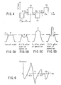
- FIG. 4 is a waveform showing an example of a driving signal that is generated from the driving signal generator 2.
- This driving signal is formed of driving pulses each including an expansion pulse P1 for increasing the capacity of the pressure chamber 11, a latency t , and a contraction pulse P2 for reducing the capacity of the pressure chamber 11.
- the gradational printing is carried out with the number of ink drops to be discharged through the nozzles 13 controlled according to the number of the driving pulses.
- a fixed delay time is set between the driving pulses.
- Tc Helmholtz resonance period of ink or the resonance period of the ink meniscus
- the printer controller 21 Since the resonance period Tc of the ink meniscus changes depending on temperature, the time lag between the expansion pulse P1 and the contraction pulse P2 can be compensated according to the temperature detected by the temperature sensor 18.
- the printer controller 21 is provided with TABLE 1, for example, and serves to correct the time lag between the expansion pulse P1 and the contraction pulse P2 according to the resonance period Tc that corresponds to the temperature detected by the temperature sensor 18.
- the resonance period Tc of the ink meniscus changes depending on the ink temperature, therefore, the time lag between the respective centers of the expansion pulse P1 and the contraction pulse P2 can be compensated correspondingly. Accordingly, the time lag between the respective centers of the expansion pulse P1 and the contraction pulse P2 can always be adjusted to the resonance period Tc of the ink meniscus.
- the expansion pulse P1 is applied to the piezoelectric member 15 in an initial state such that an ink meniscus m in each nozzle 13 is in the state shown in FIG. 5A
- the pressure chamber 11 expand so that the ink pressure in the pressure chamber lowers in the manner shown in FIG. 6.
- the ink meniscus m receives a negative pressure from the pressure chamber 11 and starts to recede, as shown in FIG. 5B.
- the ink pressure in the pressure chamber 11 is increased to become a positive pressure by pressure vibration in the manner shown in FIG. 6.
- the ink meniscus m receives the positive pressure from the pressure chamber and ceases to recede, thereby coming to a standstill. Since the extension pulse P1 then also terminates, the pressure chamber 11 contracts. When the pressure chamber 11 starts to contract, the ink pressure further increases to the highest level, whereupon the meniscus m receives the high pressure and is discharged through the nozzle 13.
- the meniscus m receives the positive pressure from the pressure chamber 11, recedes, and then comes to a standstill. At this point of time, the meniscus m is in the state shown in FIG. 5D.
- the ink discharge through the nozzle 13 is further continued by inertia, and a first ink drop is discharged. Since the contraction pulse P2 then also terminates, the pressure chamber 11 expands. When the pressure chamber 11 starts to expand, the ink pressure lowers, whereupon most of the pressure generated for the ink discharge is canceled. Thus, sudden advance of the meniscus m is restrained, so that involution of air bubbles can be prevented.
- the process of operation in the initial state and the subsequent processes are repeated.
- the meniscus temporarily recedes much deeper than in the case of the discharge of the first ink drop. Since the ink is supplied from the common pressure chamber 16 to the pressure chamber 11 owing to the surface tension of the meniscus, however, the meniscus never continues to recede if the ink drop discharged in the first cycle of operation is small.
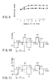
- FIG. 7 is a graph showing the relation between a driving voltage V and a time lag between the respective centers of the expansion and contraction pulses P1 and P2 obtained when seven ink drops are continuously discharged.
- Curves g1 and g2 represent the upper and lower limits, respectively of the operating voltage.
- the lower limit of the operating voltage is the lower limit of the driving voltage at which normal printing can be carried out. If the driving voltage is lower than this lower limit, the speed of discharge of ink drops is so low that the positions of impact of the ink drops vary substantially, and the printing density is too low to maintain satisfactory print quality.
- the upper limit of the operating voltage is the upper limit of the driving voltage at which the operation can be performed with stability. If the driving voltage exceeds this upper limit, the ink in the pressure chamber 11 involves air bubbles, so that ink drops cease to be discharged.
- the graph of FIG. 7 indicates that the highest driving voltage can be used for the drive when the time lag between the respective centers of the expansion and contraction pulses P1 and P2 is equal to Tc or the resonance period of a meniscus that is generated in each nozzle. This implies that the ink drops can be discharged at high speed with the least air bubbles involved when the time lag between the respective centers of the expansion and contraction pulses P1 and P2 is equal or approximate to Tc. Even if the time lag between the respective centers of the expansion and contraction pulses P1 and P2 is somewhat deviated from Tc, according to this graph, moreover, a relatively high driving voltage can be used for the drive in a relatively wide range, especially in the region higher than Tc, so that the same function and effect can be obtained.
- the expansion and contraction pulses P1 and P2 should be generated so that the time lag between their respective centers is equal to Tc.
- the time lag need not always be equal to Tc, and may be somewhat deviated from Tc.
- the ink jet recording apparatus can minimize the possibility of the ink in the nozzles 13 involving air bubbles when one pixel is subjected to gradational printing by continuously supplying the actuator with a plurality of driving signals such that the time lag between the respective centers of the expansion and contraction pulses P1 and P2 is made substantially equal to the resonance period Tc of the meniscus.
- the ink jet recording apparatus can correct the time lag Tc between the respective centers of the expansion and contraction pulses P1 and P2 in accordance with temperature information that is detected by the temperature sensor 18.
- the driving pulses each of which is composed of the extension pulse P1 with the pulse width equal to Tc/2, the latency Tc/2, and the contraction pulse P2 with the pulse width equal to Tc/2 and which are repeatedly generated with the fixed delay time have been described as an example of the driving signal that the driving signal generator 2 generates, the present invention is not limited to these signals.
- the driving signal generated from the driving signal generator 2 may be formed of driving pulses that are repeatedly generated without any delay time between them. In this case, generation of the contraction pulse P2 of one driving pulse is immediately followed by generation of the extension pulse P1 of another driving pulse.
- a contraction pulse P2' with a pulse width shorter than Tc/2 may be used as the contraction pulse without changing the position of its center, as shown in FIG. 10.
- a contraction pulse P2" with a voltage V2 that is lower than the voltage V1 of the extension pulse P1 may be used as the contraction pulse, as shown in FIG. 11.
- a moderate increase of the discharge speed allows an ink drop discharged at a time to unite with its preceding ink drop in the air, thereby improving the circularness of dots dashed against a printing medium. If the discharge speed is increased too much, however, the discharge sometimes may be unstable. In this case, it is necessary only that the pulse width or voltage of the contraction pulse be narrowed or lowered to restrain the increase of the discharge speed. By doing this, the increase of the speed of discharge of subsequent ink drops can be restrained to maintain the stability of the ink drop discharge, as indicated by curve g4 of FIG. 9.
Landscapes
- Particle Formation And Scattering Control In Inkjet Printers (AREA)
Abstract
Description
| | Tc | |
| 10°C | 4.4 µs | |
| 20°C | 4.5 µs | |
| 30°C | 4.6 µs | |
| 40°C | 4.7 µs |
Claims (6)
- An ink jet recording apparatus, which comprises a pressure chamber (11) stored with ink, a nozzle (13) communicating with the pressure chamber (11) and capable of discharging the ink from the pressure chamber, an actuator (14, 15) for increasing and reducing the capacity of the pressure chamber (11) in response to driving signals from a driving signal generator (2), and in which a plurality of ink drops are continuously discharged through the nozzle to form a pixel as the actuator (14, 15) is operated, characterized in that
the driving signal generator (2) being capable of successively generating, as the driving signals, an expansion pulse (P1) for increasing the capacity of the pressure chamber and a contraction pulse (P2) for reducing the capacity of the pressure chamber with a timing such that a time lag (Tc) between the respective centers of the expansion pulse and the contraction pulse substantially corresponds to the resonance period (Tc) of a meniscus generated in the nozzle (13) by the ink in the pressure chamber (11). - An ink jet recording apparatus according to claim 1, characterized by further comprising a temperature detector (18) for detecting the temperature of the ink in the pressure chamber (11), and
characterized in that the time lag (Tc) between the respective centers of the expansion pulse (P1) and the contraction pulse (P2) is compensated as the resonance period (Tc) of the meniscus generated in the nozzle (13) changes according to the temperature detected by the temperature detector (18). - An ink jet recording apparatus according to claim 1, characterized in that the width of the expansion pulse (P1) is adjusted to half of the resonance period (Tc) of the meniscus generated in the nozzle (13).
- An ink jet recording apparatus according to claim 2, characterized in that the width of the expansion pulse (P1) is adjusted to half of the resonance period (Tc) of the meniscus generated in the nozzle (13).
- An ink jet recording apparatus according to claim 1, characterized in that the width of the contraction pulse (P2) is shorter than the width of the expansion pulse (P1).
- An ink jet recording apparatus according to claim 1, characterized in that the voltage (V2) of the contraction pulse (P2) is lower than the voltage (V1) of the expansion pulse (P1).
Applications Claiming Priority (2)
| Application Number | Priority Date | Filing Date | Title |
|---|---|---|---|
| JP2001191800A JP3920596B2 (en) | 2001-06-25 | 2001-06-25 | Inkjet recording apparatus and inkjet recording method |
| JP2001191800 | 2001-06-25 |
Publications (3)
| Publication Number | Publication Date |
|---|---|
| EP1270224A2 true EP1270224A2 (en) | 2003-01-02 |
| EP1270224A3 EP1270224A3 (en) | 2003-08-27 |
| EP1270224B1 EP1270224B1 (en) | 2009-03-04 |
Family
ID=19030359
Family Applications (1)
| Application Number | Title | Priority Date | Filing Date |
|---|---|---|---|
| EP02013862A Expired - Lifetime EP1270224B1 (en) | 2001-06-25 | 2002-06-22 | Ink jet recording apparatus |
Country Status (4)
| Country | Link |
|---|---|
| US (1) | US6840595B2 (en) |
| EP (1) | EP1270224B1 (en) |
| JP (1) | JP3920596B2 (en) |
| DE (1) | DE60231361D1 (en) |
Cited By (2)
| Publication number | Priority date | Publication date | Assignee | Title |
|---|---|---|---|---|
| WO2005000589A1 (en) * | 2003-06-26 | 2005-01-06 | Ricoh Company, Ltd. | An image formation apparatus |
| EP1685963A3 (en) * | 2005-01-28 | 2008-09-03 | Samsung Electronics Co., Ltd. | Piezoelectric inkjet printhead having temperature sensor and method of attaching temperature sensor to inkjet printhead |
Families Citing this family (26)
| Publication number | Priority date | Publication date | Assignee | Title |
|---|---|---|---|---|
| KR100537522B1 (en) * | 2004-02-27 | 2005-12-19 | 삼성전자주식회사 | Piezoelectric type inkjet printhead and manufacturing method of nozzle plate |
| KR101041087B1 (en) * | 2004-11-17 | 2011-06-13 | 삼성전자주식회사 | Alignment agent injection device |
| JP4779578B2 (en) * | 2004-12-10 | 2011-09-28 | コニカミノルタホールディングス株式会社 | Droplet discharge apparatus and droplet discharge head driving method |
| JP4730516B2 (en) * | 2005-02-22 | 2011-07-20 | ブラザー工業株式会社 | Ink droplet ejection apparatus and ink droplet ejection method |
| JP2006231546A (en) * | 2005-02-22 | 2006-09-07 | Brother Ind Ltd | Ink droplet ejection device |
| JP2007022073A (en) | 2005-06-16 | 2007-02-01 | Toshiba Tec Corp | Ink jet head driving method and driving apparatus |
| DE602005021765D1 (en) | 2005-06-16 | 2010-07-22 | Toshiba Tec Kk | Method of operating an inkjet printhead |
| KR100702593B1 (en) * | 2006-04-17 | 2007-04-02 | 삼성전기주식회사 | Driving method of inkjet head |
| US20080061471A1 (en) * | 2006-09-13 | 2008-03-13 | Spin Master Ltd. | Decorative moulding toy |
| US7914125B2 (en) | 2006-09-14 | 2011-03-29 | Hewlett-Packard Development Company, L.P. | Fluid ejection device with deflective flexible membrane |
| US7651204B2 (en) * | 2006-09-14 | 2010-01-26 | Hewlett-Packard Development Company, L.P. | Fluid ejection device |
| JP4313388B2 (en) | 2006-10-11 | 2009-08-12 | 東芝テック株式会社 | Ink jet recording apparatus driving method and driving apparatus |
| JP5193538B2 (en) * | 2007-09-12 | 2013-05-08 | 東芝テック株式会社 | Inkjet apparatus and inkjet method |
| JP5354790B2 (en) * | 2009-09-01 | 2013-11-27 | 富士フイルム株式会社 | Inkjet head driving method and apparatus |
| JP2011104774A (en) * | 2009-11-12 | 2011-06-02 | Seiko Epson Corp | Liquid ejecting apparatus and control method thereof |
| US8328309B2 (en) | 2010-06-01 | 2012-12-11 | Kabushiki Kaisha Toshiba | Ink jet head and method of driving the same |
| JP5839028B2 (en) * | 2011-03-08 | 2016-01-06 | コニカミノルタ株式会社 | Driving method of droplet discharge head |
| JP5723804B2 (en) | 2012-02-21 | 2015-05-27 | 東芝テック株式会社 | Inkjet head and inkjet recording apparatus |
| JP5943185B2 (en) * | 2012-03-12 | 2016-06-29 | セイコーエプソン株式会社 | Liquid ejector |
| US9061490B2 (en) * | 2012-03-27 | 2015-06-23 | Kyocera Corporation | Method of driving liquid ejection head and recording apparatus |
| JP6206004B2 (en) * | 2013-08-30 | 2017-10-04 | セイコーエプソン株式会社 | Liquid ejection apparatus and control method thereof |
| JP6268929B2 (en) * | 2013-10-30 | 2018-01-31 | セイコーエプソン株式会社 | Liquid ejector |
| WO2016111688A1 (en) * | 2015-01-08 | 2016-07-14 | Hewlett-Packard Development Company, L.P. | Mobile printers |
| JP2017001240A (en) | 2015-06-08 | 2017-01-05 | 東芝テック株式会社 | Inkjet head and inkjet recording apparatus |
| JP7891361B2 (en) * | 2022-04-14 | 2026-07-16 | 理想テクノロジーズ株式会社 | Inkjet head |
| JP2024062023A (en) * | 2022-10-24 | 2024-05-09 | 株式会社リコー | LIQUID DISCHARGE HEAD, LIQUID DISCHARGE UNIT, AND DEVICE FOR DISCHARGING LIQUID |
Citations (2)
| Publication number | Priority date | Publication date | Assignee | Title |
|---|---|---|---|---|
| JPH04250045A (en) | 1990-01-08 | 1992-09-04 | Sony Tektronix Corp | Drop on demand-type ink jet printer |
| US5461493A (en) | 1991-10-07 | 1995-10-24 | Xerox Corporation | Image editing system and method have improved color key editing |
Family Cites Families (27)
| Publication number | Priority date | Publication date | Assignee | Title |
|---|---|---|---|---|
| DE2835262C2 (en) * | 1978-08-11 | 1982-09-09 | Dr.-Ing. Rudolf Hell Gmbh, 2300 Kiel | Control of an ink jet recording element |
| DE3170016D1 (en) * | 1980-10-15 | 1985-05-23 | Hitachi Ltd | Ink jet printing apparatus |
| US4563689A (en) * | 1983-02-05 | 1986-01-07 | Konishiroku Photo Industry Co., Ltd. | Method for ink-jet recording and apparatus therefor |
| US4513299A (en) | 1983-12-16 | 1985-04-23 | International Business Machines Corporation | Spot size modulation using multiple pulse resonance drop ejection |
| CA1244714A (en) | 1984-04-16 | 1988-11-15 | William J. Debonte | Method for selective multi-cycle resonant operation of an ink jet apparatus for controlling dot size |
| IT1182478B (en) * | 1985-07-01 | 1987-10-05 | Olivetti & Co Spa | PILOTING AND CANCELLATION CIRCUIT OF REFLECTED WAVES FOR AN INK JET PRINT HEAD |
| JP2854575B2 (en) * | 1986-06-20 | 1999-02-03 | キヤノン株式会社 | Ink jet recording device |
| JPS6426454A (en) | 1987-04-17 | 1989-01-27 | Canon Kk | Ink jet recorder |
| US5221931A (en) | 1988-04-26 | 1993-06-22 | Canon Kabushiki Kaisha | Driving method for ink jet recording head and ink jet recording apparatus performing the method |
| US5170177A (en) * | 1989-12-15 | 1992-12-08 | Tektronix, Inc. | Method of operating an ink jet to achieve high print quality and high print rate |
| US5155498A (en) * | 1990-07-16 | 1992-10-13 | Tektronix, Inc. | Method of operating an ink jet to reduce print quality degradation resulting from rectified diffusion |
| US5363689A (en) * | 1992-09-11 | 1994-11-15 | Intertech Development Company | Calibration device for leak detecting instruments |
| US5736993A (en) * | 1993-07-30 | 1998-04-07 | Tektronix, Inc. | Enhanced performance drop-on-demand ink jet head apparatus and method |
| US5495270A (en) * | 1993-07-30 | 1996-02-27 | Tektronix, Inc. | Method and apparatus for producing dot size modulated ink jet printing |
| US6123405A (en) * | 1994-03-16 | 2000-09-26 | Xaar Technology Limited | Method of operating a multi-channel printhead using negative and positive pressure wave reflection coefficient and a driving circuit therefor |
| US6217159B1 (en) * | 1995-04-21 | 2001-04-17 | Seiko Epson Corporation | Ink jet printing device |
| JPH0952360A (en) | 1995-04-21 | 1997-02-25 | Seiko Epson Corp | Inkjet recording device |
| US6174038B1 (en) * | 1996-03-07 | 2001-01-16 | Seiko Epson Corporation | Ink jet printer and drive method therefor |
| JPH1016211A (en) * | 1996-07-05 | 1998-01-20 | Seiko Epson Corp | Ink jet recording device |
| JP2861980B2 (en) * | 1997-01-30 | 1999-02-24 | 日本電気株式会社 | Ink drop ejector |
| DE69820201T2 (en) * | 1997-04-16 | 2004-11-04 | Seiko Epson Corp. | METHOD FOR DRIVING AN INK-JET RECORDING HEAD |
| US6029896A (en) * | 1997-09-30 | 2000-02-29 | Microfab Technologies, Inc. | Method of drop size modulation with extended transition time waveform |
| JP3475067B2 (en) | 1998-02-02 | 2003-12-08 | 東芝テック株式会社 | Driving method of inkjet printer head |
| US6478395B2 (en) | 1999-12-01 | 2002-11-12 | Seiko Epson Corporation | Liquid jetting apparatus |
| JP3920022B2 (en) | 1999-12-01 | 2007-05-30 | セイコーエプソン株式会社 | Liquid ejector |
| US6422684B1 (en) * | 1999-12-10 | 2002-07-23 | Sensant Corporation | Resonant cavity droplet ejector with localized ultrasonic excitation and method of making same |
| JP2001328259A (en) * | 2000-05-18 | 2001-11-27 | Nec Corp | Driving method of inkjet recording head and inkjet recording apparatus |
-
2001
- 2001-06-25 JP JP2001191800A patent/JP3920596B2/en not_active Expired - Lifetime
-
2002
- 2002-06-19 US US10/175,205 patent/US6840595B2/en not_active Expired - Lifetime
- 2002-06-22 EP EP02013862A patent/EP1270224B1/en not_active Expired - Lifetime
- 2002-06-22 DE DE60231361T patent/DE60231361D1/en not_active Expired - Lifetime
Patent Citations (2)
| Publication number | Priority date | Publication date | Assignee | Title |
|---|---|---|---|---|
| JPH04250045A (en) | 1990-01-08 | 1992-09-04 | Sony Tektronix Corp | Drop on demand-type ink jet printer |
| US5461493A (en) | 1991-10-07 | 1995-10-24 | Xerox Corporation | Image editing system and method have improved color key editing |
Cited By (6)
| Publication number | Priority date | Publication date | Assignee | Title |
|---|---|---|---|---|
| WO2005000589A1 (en) * | 2003-06-26 | 2005-01-06 | Ricoh Company, Ltd. | An image formation apparatus |
| KR100741542B1 (en) * | 2003-06-26 | 2007-07-20 | 가부시키가이샤 리코 | an Image Formation Apparatus |
| CN100420574C (en) * | 2003-06-26 | 2008-09-24 | 株式会社理光 | image forming device |
| US7794034B2 (en) | 2003-06-26 | 2010-09-14 | Ricoh Company, Ltd. | Image formation apparatus |
| EP1685963A3 (en) * | 2005-01-28 | 2008-09-03 | Samsung Electronics Co., Ltd. | Piezoelectric inkjet printhead having temperature sensor and method of attaching temperature sensor to inkjet printhead |
| US7588307B2 (en) | 2005-01-28 | 2009-09-15 | Samsung Electronics Co., Ltd. | Piezolelectric inkjet printhead having temperature sensor and method of making the same |
Also Published As
| Publication number | Publication date |
|---|---|
| JP2003001821A (en) | 2003-01-08 |
| EP1270224B1 (en) | 2009-03-04 |
| JP3920596B2 (en) | 2007-05-30 |
| US20030001912A1 (en) | 2003-01-02 |
| DE60231361D1 (en) | 2009-04-16 |
| US6840595B2 (en) | 2005-01-11 |
| EP1270224A3 (en) | 2003-08-27 |
Similar Documents
| Publication | Publication Date | Title |
|---|---|---|
| EP1270224B1 (en) | Ink jet recording apparatus | |
| US5552809A (en) | Method for driving ink jet recording head and apparatus therefor | |
| US6488349B1 (en) | Ink-jet head and ink-jet type recording apparatus | |
| EP0979732B1 (en) | Method of driving an ink jet recording head | |
| US6685293B2 (en) | Liquid jetting apparatus and method of driving the same | |
| US8186791B2 (en) | Liquid ejecting apparatus and control method thereof | |
| US6419337B2 (en) | Ink jet recording apparatus and method of driving the same | |
| JP2000117969A (en) | Driving method of inkjet recording head | |
| EP0858892B1 (en) | Ink jet recording apparatus | |
| EP1023997A2 (en) | Actuator device and ink jet recording apparatus | |
| JP2007022073A (en) | Ink jet head driving method and driving apparatus | |
| JP2018043365A (en) | Ink jet head driving device and ink jet head | |
| JP4237382B2 (en) | Inkjet head drive device | |
| JP3500692B2 (en) | Ink jet recording device | |
| JP3959809B2 (en) | Ink jet printer, and recording head drive apparatus and method for ink jet printer | |
| WO2005120840A1 (en) | Ink jet recording device and ink jet recording method | |
| JP2009154493A (en) | Ink jet head driving method and driving apparatus | |
| JP2002225250A (en) | Ink jet recording device | |
| JP2785701B2 (en) | Ink jet printer head and driving method thereof | |
| JP7785546B2 (en) | Liquid ejection head | |
| JP5481618B2 (en) | Inkjet recording apparatus and inkjet head driving method | |
| JP2007118294A (en) | Ink jet head driving apparatus and driving method | |
| US20250170823A1 (en) | Liquid ejection drive device | |
| JP3648598B2 (en) | Ink ejection control method and ink ejection apparatus | |
| JP2025032915A (en) | Drive unit |
Legal Events
| Date | Code | Title | Description |
|---|---|---|---|
| PUAI | Public reference made under article 153(3) epc to a published international application that has entered the european phase |
Free format text: ORIGINAL CODE: 0009012 |
|
| 17P | Request for examination filed |
Effective date: 20020622 |
|
| AK | Designated contracting states |
Kind code of ref document: A2 Designated state(s): AT BE CH CY DE DK ES FI FR GB GR IE IT LI LU MC NL PT SE TR |
|
| AX | Request for extension of the european patent |
Free format text: AL;LT;LV;MK;RO;SI |
|
| PUAL | Search report despatched |
Free format text: ORIGINAL CODE: 0009013 |
|
| AK | Designated contracting states |
Designated state(s): AT BE CH CY DE DK ES FI FR GB GR IE IT LI LU MC NL PT SE TR |
|
| AX | Request for extension of the european patent |
Extension state: AL LT LV MK RO SI |
|
| AKX | Designation fees paid |
Designated state(s): BE DE FR GB |
|
| 17Q | First examination report despatched |
Effective date: 20060109 |
|
| GRAP | Despatch of communication of intention to grant a patent |
Free format text: ORIGINAL CODE: EPIDOSNIGR1 |
|
| GRAS | Grant fee paid |
Free format text: ORIGINAL CODE: EPIDOSNIGR3 |
|
| GRAA | (expected) grant |
Free format text: ORIGINAL CODE: 0009210 |
|
| AK | Designated contracting states |
Kind code of ref document: B1 Designated state(s): BE DE FR GB |
|
| REG | Reference to a national code |
Ref country code: GB Ref legal event code: FG4D |
|
| REF | Corresponds to: |
Ref document number: 60231361 Country of ref document: DE Date of ref document: 20090416 Kind code of ref document: P |
|
| PG25 | Lapsed in a contracting state [announced via postgrant information from national office to epo] |
Ref country code: BE Free format text: LAPSE BECAUSE OF FAILURE TO SUBMIT A TRANSLATION OF THE DESCRIPTION OR TO PAY THE FEE WITHIN THE PRESCRIBED TIME-LIMIT Effective date: 20090304 |
|
| PLBE | No opposition filed within time limit |
Free format text: ORIGINAL CODE: 0009261 |
|
| STAA | Information on the status of an ep patent application or granted ep patent |
Free format text: STATUS: NO OPPOSITION FILED WITHIN TIME LIMIT |
|
| 26N | No opposition filed |
Effective date: 20091207 |
|
| PGFP | Annual fee paid to national office [announced via postgrant information from national office to epo] |
Ref country code: FR Payment date: 20100709 Year of fee payment: 9 |
|
| REG | Reference to a national code |
Ref country code: FR Ref legal event code: ST Effective date: 20120229 |
|
| PG25 | Lapsed in a contracting state [announced via postgrant information from national office to epo] |
Ref country code: FR Free format text: LAPSE BECAUSE OF NON-PAYMENT OF DUE FEES Effective date: 20110630 |
|
| PGFP | Annual fee paid to national office [announced via postgrant information from national office to epo] |
Ref country code: DE Payment date: 20120620 Year of fee payment: 11 |
|
| PGFP | Annual fee paid to national office [announced via postgrant information from national office to epo] |
Ref country code: GB Payment date: 20120620 Year of fee payment: 11 |
|
| GBPC | Gb: european patent ceased through non-payment of renewal fee |
Effective date: 20130622 |
|
| REG | Reference to a national code |
Ref country code: DE Ref legal event code: R119 Ref document number: 60231361 Country of ref document: DE Effective date: 20140101 |
|
| PG25 | Lapsed in a contracting state [announced via postgrant information from national office to epo] |
Ref country code: DE Free format text: LAPSE BECAUSE OF NON-PAYMENT OF DUE FEES Effective date: 20140101 Ref country code: GB Free format text: LAPSE BECAUSE OF NON-PAYMENT OF DUE FEES Effective date: 20130622 |