EP1270222A2 - Imaging apparatus and printing plate mounting surface having registration detection - Google Patents
Imaging apparatus and printing plate mounting surface having registration detection Download PDFInfo
- Publication number
- EP1270222A2 EP1270222A2 EP02077371A EP02077371A EP1270222A2 EP 1270222 A2 EP1270222 A2 EP 1270222A2 EP 02077371 A EP02077371 A EP 02077371A EP 02077371 A EP02077371 A EP 02077371A EP 1270222 A2 EP1270222 A2 EP 1270222A2
- Authority
- EP
- European Patent Office
- Prior art keywords
- electrical
- printing plate
- conductors
- signal
- mounting surface
- Prior art date
- Legal status (The legal status is an assumption and is not a legal conclusion. Google has not performed a legal analysis and makes no representation as to the accuracy of the status listed.)
- Withdrawn
Links
Images






Classifications
-
- B—PERFORMING OPERATIONS; TRANSPORTING
- B41—PRINTING; LINING MACHINES; TYPEWRITERS; STAMPS
- B41C—PROCESSES FOR THE MANUFACTURE OR REPRODUCTION OF PRINTING SURFACES
- B41C1/00—Forme preparation
- B41C1/10—Forme preparation for lithographic printing; Master sheets for transferring a lithographic image to the forme
- B41C1/1083—Mechanical aspects of off-press plate preparation
-
- B—PERFORMING OPERATIONS; TRANSPORTING
- B41—PRINTING; LINING MACHINES; TYPEWRITERS; STAMPS
- B41P—INDEXING SCHEME RELATING TO PRINTING, LINING MACHINES, TYPEWRITERS, AND TO STAMPS
- B41P2227/00—Mounting or handling printing plates; Forming printing surfaces in situ
- B41P2227/30—Detecting the correct position of printing plates on the cylinder
Definitions
- the present invention relates to imaging apparatuses and imaging drums for use in an imaging apparatus that forms an image on printing plates or uses a printing plate to apply ink to a receiver media to form an image.
- the present invention relates to an imaging apparatus and imaging drum having automatic plate registration detection.
- Contact printing remains the most economical method for printing a large number of copies of an image.
- Contact printing presses utilize printing plates to apply ink to a receiver media to form an image on the media.
- the printing plates have a printing surface with a pattern of markings representing the image to be printed.
- the printing plate Prior to printing, the printing plate is fixed to a plate mounting surface.
- ink is applied to the printing surface and the printing surface is brought into contact with a receiver media such as paper. An ink pattern is thereby transferred to the receiver media forming an image on the receiver media.
- a printing plate that is properly aligned and positioned is known in the art as being "in registration.”
- each printing plate applies a differently colored ink to the receiver media.
- the image formed on the receiver media can contain different colors. It will be understood that each printing plate must be in registration when the color image is formed. If the printing plates are not in registration, the image will appear out of focus and the colors in the image will be incorrect.
- a printing plate imaging apparatus is used to form the image on the printing plate. It is necessary to properly register the printing plate during this process. If a printing plate is not in registration when an image is formed on the printing plate, then the printing plate will not generate proper images when it is used for printing.
- U.S. Pat. No. 5,992, 325 shows a method and device for automatically detecting the location of at least one printing plate edge on a plate mounting surface.
- a plate cylinder for a printing press includes a linear array of clamps that hold a trailing or leading edge of the printing plate. Mechanical sensors in the clamps trigger electrical switches. The switches provide an electrical indication of whether the trailing or leading edge of printing plate is positioned within the clamps. When the edge of the plate is detected at each clamp in the array, the plate is considered to be in registration.
- U.S. Pat. Nos. 3,595,567 and 4,127, 265 show similar structures for determining whether a sheet of receiver media is in registration with a drum. Each of these patents shows two linear arrays of clamps or grippers positioned on opposite sides of the drum. This allows two sheets of material to be held to the drum thus requiring two sets of sensors to detect the alignment of the sheets. U.S. Pat. No. 2,145,520 shows a mechanical structure to accomplish this result.
- U.S. Pat. No. 5,479,859 shows a method and apparatus for controlling an automated printing plate change process in a sheet-fed offset printing machine.
- a pair of clamps are used to hold a printing plate in registration.
- the clamps are arranged in a linear fashion on the drum and have register pins to grip printing plates against a gripping portion.
- the register pins are electrically insulated from the gripping portion and engage notches in the plate.
- bottom edges of the notches seat on and contact the register pins. This provides a conductive electrical path from the register pins to the gripping portion. By sensing whether such a conductive path is formed at each register pin, it becomes possible to determine whether the printing plate is in registration.
- the prior art relies upon the detection of the leading or trailing edge of the printing plate and determines whether the printing plate is in registration based upon the signals received from two or more sensors aligned along a single direction that is parallel with either the leading or trailing edge of the printing plate.
- Such systems can fail to detect lateral mis-position of the printing plate.
- Such systems are not easily adaptable to accommodate different sizes of printing plates. This is because smaller printing plates may not extend across the linear direction of the clamps so that each clamp contacts a portion of the leading or trailing edge of the plate. In such a circumstance, a drum of the prior art will erroneously indicate that a smaller printing plate is not in registration.
- an imaging apparatus for forming images on an electrically conductive printing plate.
- the imaging apparatus has a mounting surface having at least three electrically isolated conductors arranged so that when the electrically conductive printing plate is in registration on the mounting surface, the electrically conductive printing plate defines an electrical connection between all of the electrical conductors and, an electrical circuit adapted to sense an electrical connection between all of the conductors and to thereupon generate an output signal.
- a mounting surface for receiving electrically conductive printing plates has at least three electrically isolated conductors arranged so that when the electrically conductive printing plate is in registration on the mounting surface the electrically conductive printing plate defines an electrical connection between all of the electrical conductors and an electrical circuit adapted to sense an electrical connection between all of the conductors and to thereupon generate an output signal.
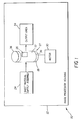
- Imaging apparatus 20 used to form images on a printing plate.
- Imaging apparatus 20 comprises a housing 22, plate supply 24, an imager 26 a motor 30 and an output area 34.
- the mounting surface 27 comprises an imaging drum 28.
- Imaging drum 28 comprises a cylindrical shaped imaging drum 28 having an outer surface 38, which can, for example, be manufactured from a length of extruded aluminum tubing.
- Imaging drum 28 is adapted to secure printing plate 36 to outer surface 38 using vacuum or electrostatic attraction. Imaging drum 28 can also have clamps or fasteners (not shown) to secure printing plate 36 to outer surface 38.
- printing plate 36 is transported to imaging drum 28, registered on outer surface 38 of imaging drum 28, and secured to outer surface 38 on imaging drum 28.
- motor 30 rotates imaging drum 28 to move printing plate 36 past imager 26.
- Imager 26 forms an image on printing surface 37 of printing plate 36.
- printing plate 36 is transported to output area 34. It will be noted that printing plate 36 can be registered, secured to, and removed from imaging drum 28 manually or automatically.
- Fig. 2a shows a planar view of the outer surface 38 of imaging drum 28 of the present invention.
- imaging drum 28 has an imaging area 40 defined by axial boundaries 42 and 44 and lateral boundaries 46 and 48.
- imaging drum 28 is rotated along direction 50 while imager 26 (not shown) writes images generally along writing direction 52.
- Writing direction 52 is shown as being perpendicular to direction of rotation 50, however, it is not necessary to write an image using a path that is perpendicular to the direction of rotation 50.
- Fig. 2b shows a planar view of a printing plate 36 of the type used in conjunction with the present invention.
- printing plate 36 has a leading axial edge 54, a trailing axial edge 56, a left lateral edge 58, and a right lateral edge 60.
- Printing plate 36 can be formed from an electrically conductive metallic substrate. However, printing plate 36 can also be formed from a plastic or other substrate having a conductive coating, exterior layer or wrapping.
- Fig. 3a shows a planar view of an outer surface 38 of imaging drum 28 having a printing plate 36 in registration. As is shown in Fig. 3a, printing plate 36 is in registration when leading edge 54 is aligned with first axial boundary 42 and right lateral edge 60 is aligned with right lateral boundary 48.
- Fig. 3b shows a planar view of an imaging drum 28 having a printing plate 36 mounted on imaging drum 28 so that leading edge 54 is not aligned with first axial boundary 42. This is known as mis-registration. Another type of error known as mis-positioning can also occur. Mis-positioning can occur where printing plate 36 is not aligned with boundaries 42 and 48 as is shown in Fig. 3c and Fig. 3d. In Fig. 3c, printing plate 36 is mis-positioned because leading axial edge 54 is not aligned with axial boundary 42. In Fig. 3d, printing plate 36 is mis-positioned because right edge 60 is not aligned with lateral boundary 48.
- Figs. 4a and 4b show, respectively, a schematic cross-section side view of imaging drum 28 of the present invention with printing plate 36 secured to outer surface 38 of imaging drum 28.
- imaging drum 28 has an outer surface 38 that includes a first electrical conductor 62, a second electrical conductor 64, and a third electrical conductor 66.
- First electrical conductor 62 and second electrical conductor 64 are positioned to form a first axial boundary 42 to engage leading longitudinal edge 54.
- Third electrical conductor 66 is positioned apart from first axial boundary 42 and is positioned to engage right lateral edge 60 of printing plate 36 and thus to define a right lateral boundary 48.
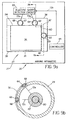
- Fig. 4b shows that each of electrical conductors 62 (not shown), 64, and 66, protrudes radially outward from outer surface 38 to engage an edge of printing plate 36. This permits printing plate 36 to be placed in registration by positioning printing plate 36 in a position where leading edge 54 contacts first electrical conductor 62 and second electrical conductor 64 and positioning right lateral edge 60 in contact with third electrical conductor 66. When printing plate 36 is in contact with each of conductors 62, 64, and 66, printing plate 36 is in registration on imaging drum 28.
- the imaging drum 28 of the present invention is adapted to electronically detect when printing plate 36 is in contact with each of conductors 62, 64 and 66.
- electrical conductors 62, 64 and 66 are surrounded by electrical insulating material 68. Electrical insulating material 68 electrically isolates each of electrical conductors 62, 64, and 66 from outer surface 38 and from each other.
- printing plate 36 when the edges of printing plate 36 contacts all of the electrical conductors 62, 64, and 66, printing plate 36 creates a short between electrical conductors 62, 64 and 66. However, if printing plate 36 fails to directly contact each of electrical conductors 62, 64 and 66, then no short is created. Thus, even a small electrical gap between printing plate 36 and conductors 62, 64 and 66 will prevent the formation of the short. Accordingly, by using the imaging drum 28 of the illustrated embodiment of the present invention, it is possible to determine whether printing plate 36 is in registration simply by testing whether a short exists between each of the conductors 62, 64 and 66. The present invention thus uses printing plate 36 as an AND gate providing a selected electrical output - a short between the conductors 62, 64, and 66 - only when printing plate 36 is positioned in contact with each of conductors 62, 64 and 66.
- an electrical short detection circuit (not shown) is connected to each of the conductors 62, 64 and 66.
- the electrical short detection circuit generates an output signal that is indicative of whether a short exists.
- the imaging drum 28 is adapted to permit an electrical short detection circuit (not shown) that is external to imaging drum 28 to detect the electrical short.
- each of the electrical conductors 62, 64 and 66 are electrically connected by way of transmission lines 72a, 72b and 72c to contacts 74a, 74b and 74c.
- Contacts 74a, 74b, and 74c are positioned on an exterior surface of imaging drum 28 including but not limited to outer surface 38, end caps (not shown) of imaging drum 28 or a drum central shaft 80 as is shown in Fig. 4b.
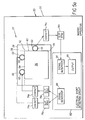
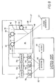
- Fig. 5a shows a schematic diagram of an imaging apparatus 20 of the present invention showing the electrical signal path created between connectors 62, 64, and 66, plate 36 and electrical short detection circuit 82 when imaging drum 28 is installed in imaging apparatus 20.
- slip rings 76a, 76b and 76c engage contacts 74a, 74b and 74c.
- This forms an electrical short detection connection that permits electrical circuit 82 to detect electrical conditions at electrical conductors 62, 64 and 66 before, during, and after rotation of the imaging drum 28.
- Electrical short detection circuit 82 is adapted to determine when a short exists between each of conductors 62, 64 and 66. Electrical circuit 82 generates an output that indicates whether the short exists.
- Fig. 5a shows an embodiment of the present invention wherein electrical short detection circuit 82 comprises a signal generator 84 that generates an electrical signal at conductors 62 and 64.
- electrical short detection circuit 82 also comprises a signal detector 86 that senses electrical signals at conductor 66.
- a signal detector 86 that senses electrical signals at conductor 66.
- detector 86 receives signals from both of conductors 62 and 64, it generates a signal activating an output 88 indicating that printing plate 36 is in registration.
- Output 88 can comprise a display, an audible warning or other warning.
- Output 88 can also comprise an input to a controller (not shown) for the imaging apparatus 20.
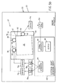
- Fig. 5b shows the operation of the embodiment of Fig. 5a wherein printing plate 36 is mounted on imaging drum 28 so that leading edge 54 is not aligned with first axial boundary 42.
- signal detector 86 only detects the signal from conductor 64 and activates an output to indicate that printing plate 36 is not in registration.
- Signal detector 86 can optionally be adapted to identify the conductor from which a signal is not received and to cause output 88 to identify this conductor.
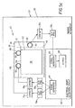
- Fig. 5c shows the operation of the embodiment of Fig. 5a, wherein printing plate 36 is mounted on imaging drum 28 so that right edge 58 is not aligned with right lateral boundary 48. In this situation, no signals are received by conductor 66 and detector 86 generates a signal causing output 88 to indicate that printing plate 36 is not in registration.
- Fig. 5d shows the operation of the embodiment of Fig. 5a wherein printing plate 36 is mounted on imaging drum 28 so that leading axial edge 54 is not aligned with axial boundary 42.
- detector 86 does not receive any signals from connectors 62 or 64. Because of this, detector 86 generates a signal causing output 88 to indicate that printing plate 36 is not in registration.
- the present invention can be configured to work with electrical signals in many forms.
- signal generator 84 and signal detector 86 can be adapted to generate and detect, respectively, steady state signals, binary signals and/or phase, amplitude or frequency modulated signals.
- signal generator 84 is adapted to provide unique electrical signals at conductors 62 and 64.
- signal detector 86 is adapted to identify which of conductors 62 and 64 is not in contact with printing plate 36 by examination of the signals that are received at conductor 66.
- signal generator 84 can generate a first voltage signal having a frequency of 20 Hz at conductor 62 and a second voltage signal having a frequency of 25 Hz at conductor 64.
- signal detector 86 can be adapted to determine that printing plate 36 is in registration when both signals are detected, that printing plate 36 is not in contact with conductor 62 when only a 20 Hz signal is received and that printing plate 36 is not in contact with conductor 64 when only a 25 Hz signal is received.
- the present invention can easily accommodate printing plates 36 having various sizes while still ensuring that leading edge 54 and right lateral edge 60 are aligned and that printing plate 36 is in registration.
- Fig. 7 shows an alternative embodiment of the present invention.
- signal generator 84 generates electrical signals for each of conductors 62, 64, and 66.
- printing plate 36 is grounded.
- signal generator 84 is adapted to detect when the load reaches a threshold.
- signal generator 86 generates an output signal indicating that printing plate 36 is in registration.
- drum 28 is adapted to electro-statically attract printing plate 36 to outer surface 68.
- charge generator 90 generates an electrostatic charge at outer surface 38 of imaging drum 28. This charge acts on printing plate 36 when printing plate 36 is positioned on the outer surface 38 of drum 28.
- Conductors 62, 64, and 66 are insulated from this charge by insulating material 68. Conductors 62, 64, and 66 therefore are only exposed to electrostatic charge on outer surface 68 by way of contact with printing plate 36.
- signal detector 86 is connected to each of conductors 62, 64, and 66 and detects the presence of electrostatic charge from printing plate 36 and each of the conductors. When electrostatic charge is detected at each of conductors 62, 64, and 66, detector 86 generates a signal causing output 88 to indicate that printing plate 36 is in registration.
- FIGs. 9a and 9b show an imaging drum 28 of the present invention incorporating an electrical short detection circuit 82.
- electrical short detection circuit 82 is connected to each of conductors 62, 64 and 66 and detects the existence of an electrical short between these conductors. Where an electrical short is detected between conductors 62, 64, and 66, electrical short detection circuit 82 generates an output to indicate that printing plate 36 is in registration. Electrical short detection circuit 82 can also generate an output to indicate when printing plate 36 is not in registration on outer surface 38.
- This output may be in the form of an electrical signal, an optical signal, audible signal or a radio frequency signal.
- the electrical signal, optical signal, audible signal, or radio frequency signal from imaging drum 28 can be received by controller 95 of imaging apparatus 20 and used to prevent or to interrupt imaging operations until printing plate 36 can be placed in registration on outer surface 38.
- radio frequency communications are used to indicate the presence or absence of an electric charge at conductors 62, 64, and 66.
- an electric signal is provided at each of conductors 62 and 64.
- Conductor 66 is connected by way of a tuned coil 94 to a ground.
- the electric signal at conductors 62 and 64 flows to conductor 66 and from there through tuned coil 94 to ground. This causes a radio frequency signal to emit from the tuned coil.
- a radio frequency detector 96 positioned outside of imaging drum 28 detects the radio frequency signal and analyzes the signal to ensure that the radio frequency signal transmitted by tuned coil 94 is indicative of a signal that would be transmitted by a tuned coil 94 that receives signals from both conductors 62 and 64.
- the radio frequency signal from tuned coil 94 can be received by controller 95 of imaging apparatus 20 and used to prevent or to interrupt imaging operations until printing plate 36 can be placed in registration on outer surface 38.
- the present invention has generally been described as being used in conjunction with an imaging apparatus 20 for forming an image on a printing plate 36. It will be appreciated however that the imaging apparatus 20 of the present invention can also comprise a contact printer 100 having amounting surface 27 adapted for contact printing using a printing plate.
- a printing press is shown in schematic form in Fig. 11.
- contact printer 100 comprises an imaging drum 28 having a printing plate 36 fixed thereto, a source of receiver media 110, a donor material applicator 112, a contact sleeve 114 and an output area 116.
- printing plate 36 is positioned on the outside surface 38 of imaging drum 28.
- Motor 30 rotates imaging drum 28, bringing printing plate 36 into contact with donor material applicator 112.
- imaging drum 28 is adapted to transmit a radio frequency signal that indicates whether printing plate 36 is in registration. This radio frequency signal is received by radio frequency detector 96 which provides a signal to controller 95.
- electrical conductor of the present invention have been described and shown as being stand alone structures.
- electrical conductors 62, 64 and 66 can be incorporated into other structures such as a clamp 130 that are used to hold printing plate 36 to imaging drum 28.
- An example of this is shown in Fig. 12 wherein conductor 62 is incorporated into a clamp 130 located on imaging drum 128.
- slide 132 is magnetically biased by magnet 134 to hold plate 36 against retainer 136.
- slide 132 acts as an electrical short detection conductor 62 and is connected by way of conductor 72a to electrical circuit 82.
- the mounting surface 27 of the present invention has been described as being an imaging drum 28.
- the mounting surface 27 of the present invention can comprise any number of surfaces that are adapted to receive and hold a printing plate 36.
- Figs. 13a and 13b show a top and cross-section view of an embodiment of the present invention wherein the mounting surface 27 comprises a mounting platen 140.
- mounting platen 140 has a planar outer surface 38 adapted to hold printing plate 36 to the mounting surface 27.
- This embodiment of the present invention can incorporate any of the above described features of any embodiment of the present invention described with respect to imaging drum 28.
- mounting surface 27 can also comprise other convenient forms well known to those in the art of printing including, but not limited to, a printing plate.
- printing plate 36 may have other edge features that will require different arrangements of electrical conductors 62, 64 and 66 in order to detect proper registration of such a printing plate 36.
Landscapes
- Engineering & Computer Science (AREA)
- Mechanical Engineering (AREA)
- Manufacturing & Machinery (AREA)
- Exposure And Positioning Against Photoresist Photosensitive Materials (AREA)
- Manufacture Or Reproduction Of Printing Formes (AREA)
- Camera Bodies And Camera Details Or Accessories (AREA)
- Preparing Plates And Mask In Photomechanical Process (AREA)
Abstract
Description
There have been various attempts to meet this need in the prior art. For example U.S. Pat. No. 5,992, 325 shows a method and device for automatically detecting the location of at least one printing plate edge on a plate mounting surface. As shown in this patent, a plate cylinder for a printing press includes a linear array of clamps that hold a trailing or leading edge of the printing plate. Mechanical sensors in the clamps trigger electrical switches. The switches provide an electrical indication of whether the trailing or leading edge of printing plate is positioned within the clamps. When the edge of the plate is detected at each clamp in the array, the plate is considered to be in registration.
Each of these patents shows two linear arrays of clamps or grippers positioned on opposite sides of the drum. This allows two sheets of material to be held to the drum thus requiring two sets of sensors to detect the alignment of the sheets. U.S. Pat. No. 2,145,520 shows a mechanical structure to accomplish this result.
Claims (10)
- An imaging apparatus for forming images on an at least partially electrically conductive printing plate; the imaging apparatus comprising:a mounting surface having at least three electrically isolated conductors arranged so that when the electrically conductive printing plate is in registration on the mounting surface the electrically conductive printing plate defines an electrical connection between all of the electrical conductors; and,an electrical circuit adapted to sense an electrical connection between all of the conductors and to thereupon generate an output signal.
- The imaging apparatus of claim 1 wherein the electrical circuit comprises a signal detector adapted to sense electrical signals at a first electrical conductor and an electrical signal generator generating an electrical signal at each of the remaining electrical conductors wherein the signal detector is adapted to generate an output when a signal at the first electrical conductor includes a signal from all of the remaining electrical conductors.
- The imaging apparatus of claim 2, wherein the signal generator generates different electrical signals at each of the remaining electrical conductors and wherein the signal detector is adapted to detect each electrical signal and to generate a second output identifying the electrical conductors that are in contact with the printing plate.
- The imaging apparatus of claim 1, further comprising a ground electrically connected to the printing plate wherein the electrical circuit comprises an electrical signal generator generating an electrical signal at each of the electrical conductors and the electrical signal generator is adapted to sense an electrical connection between the electrical conductors by detecting a ground at each of the conductors.
- The imaging apparatus of claim 1, wherein the output signal comprises a radio frequency signal and wherein the imaging apparatus has a radio frequency receiver to detect the radio frequency signal.
- The imaging apparatus of claim 1, wherein the mounting surface comprises a rotatable drum.
- The imaging apparatus of claim 1, wherein the mounting surface comprises a platen.
- A mounting surface for receiving electrically conductive printing plates; the mounting surface comprising:an outer surface having at least three electrically isolated conductors arranged so that when the electrically conductive printing plate is in registration on the mounting surface the electrically conductive printing plate defines an electrical connection between all of the electrical conductors; and,an electrical circuit adapted to sense an electrical connection between all of the conductors and to thereupon generate an output.
- The mounting surface of claim 8 wherein the electrical circuit comprises a signal detector adapted to sense electrical signals at a first electrical conductor and an electrical signal generator generating an electrical signal at each of the remaining electrical conductors wherein the signal detector is adapted to generate an output when a signal at the first electrical conductor includes a signal from all of the remaining electrical conductors.
- The imaging apparatus of claim 8, wherein the printing plate has at least two electrically conductive edges and the electrical conductors extend from the mounting surface to define electrically conductive abutments.
Applications Claiming Priority (2)
| Application Number | Priority Date | Filing Date | Title |
|---|---|---|---|
| US894551 | 2001-06-28 | ||
| US09/894,551 US6510793B1 (en) | 2001-06-28 | 2001-06-28 | Imaging apparatus and printing plate mounting surface for use in an imaging apparatus having printing plate registration detection |
Publications (2)
| Publication Number | Publication Date |
|---|---|
| EP1270222A2 true EP1270222A2 (en) | 2003-01-02 |
| EP1270222A3 EP1270222A3 (en) | 2007-03-14 |
Family
ID=25403230
Family Applications (1)
| Application Number | Title | Priority Date | Filing Date |
|---|---|---|---|
| EP02077371A Withdrawn EP1270222A3 (en) | 2001-06-28 | 2002-06-17 | Imaging apparatus and printing plate mounting surface having registration detection |
Country Status (3)
| Country | Link |
|---|---|
| US (1) | US6510793B1 (en) |
| EP (1) | EP1270222A3 (en) |
| JP (1) | JP2003112400A (en) |
Cited By (2)
| Publication number | Priority date | Publication date | Assignee | Title |
|---|---|---|---|---|
| WO2008121237A1 (en) | 2007-03-29 | 2008-10-09 | Eastman Kodak Company | Printing plate registration using a camera |
| EP1826004A3 (en) * | 2006-02-22 | 2010-12-08 | Rolf-Peter Lehner | Device for adjusting and/or identifying printing plates on printing cylinders of a printing machine |
Families Citing this family (16)
| Publication number | Priority date | Publication date | Assignee | Title |
|---|---|---|---|---|
| US6739250B2 (en) * | 2002-03-20 | 2004-05-25 | Fuji Photo Film Co., Ltd. | Device for controlling rotation of rotating drum |
| US7456379B2 (en) * | 2003-02-03 | 2008-11-25 | Kodak Graphic Communications Canada Company | Printing plate registration and optical alignment device including locating at least a part of a reference edge in at least one digital camera image |
| US20070227386A1 (en) * | 2006-04-03 | 2007-10-04 | Mcgaire Mark D | Plate processing system and method |
| US20070227384A1 (en) * | 2006-04-03 | 2007-10-04 | Mcgaire Mark D | Imaging and punching thermal control system |
| US7621219B2 (en) * | 2006-05-26 | 2009-11-24 | Burgess Industries, Inc. | Method and apparatus for registration of an imaged lithographic plate |
| DE102008005878B4 (en) * | 2007-02-09 | 2014-05-15 | Heidelberger Druckmaschinen Ag | Method for aligning a pressure plate to a stop |
| US8210104B2 (en) * | 2008-10-23 | 2012-07-03 | Eastman Kodak Company | Moveable printing plate registration member |
| US8176846B2 (en) * | 2008-10-23 | 2012-05-15 | Eastman Kodak Company | Printing plate positioning |
| US20110192303A1 (en) * | 2010-02-05 | 2011-08-11 | Hines Ryan K | Detection of misregistered printing plate |
| US8511227B2 (en) | 2010-02-05 | 2013-08-20 | Eastman Kodak Company | Printing plate registration |
| US8286553B2 (en) * | 2010-03-24 | 2012-10-16 | Eastman Kodak Company | Wiffle-tree printing plate registration system |
| US8950326B1 (en) | 2012-04-19 | 2015-02-10 | Laser Dot Holding B.V. | Method and apparatus for laser ablating an image on a mounted blank printing plate |
| US9573478B2 (en) | 2014-11-14 | 2017-02-21 | Schneider Electric USA, Inc. | EVSE doubler add-on unit |
| US9804034B2 (en) | 2014-11-14 | 2017-10-31 | Schneider Electric USA, Inc. | EVSE with cordset handle temperature measurement |
| US9707850B2 (en) | 2014-11-18 | 2017-07-18 | Schneider Electric USA, Inc. | EVSE handle with automatic thermal shut down by NTC to ground |
| US20180072046A1 (en) * | 2016-09-12 | 2018-03-15 | M&R Printing Equipment, Inc. | Alignment indicator for registration system |
Family Cites Families (19)
| Publication number | Priority date | Publication date | Assignee | Title |
|---|---|---|---|---|
| US2145520A (en) | 1937-03-11 | 1939-01-31 | Martin Machinery Corp | Gathering machine |
| US3191530A (en) | 1963-11-18 | 1965-06-29 | Cutler Hammer Inc | Detector system for plural unit printing press |
| US3595567A (en) | 1969-01-17 | 1971-07-27 | Harris Intertype Corp | Sheet detection control for sheet-handling apparatus,particulary a printing press |
| DE2621250C2 (en) | 1976-05-13 | 1982-07-22 | Heidelberger Druckmaschinen Ag, 6900 Heidelberg | Sheet query device in a rotary printing press |
| DE3936446A1 (en) * | 1989-11-02 | 1991-05-08 | Miller Johannisberg Druckmasch | PLATE CYLINDER OF A PRINTING MACHINE |
| JP3194199B2 (en) * | 1992-01-17 | 2001-07-30 | 株式会社小森コーポレーション | Plate mounting device on plate cylinder |
| JP3379974B2 (en) * | 1992-02-10 | 2003-02-24 | 株式会社小森コーポレーション | Plate mounting status confirmation device |
| JP2573523Y2 (en) * | 1992-07-31 | 1998-06-04 | 株式会社小森コーポレーション | Plate mounting device for printing press |
| DE4226780C2 (en) * | 1992-08-13 | 1994-12-01 | Roland Man Druckmasch | Device for checking the correct registration of a printing plate on the plate cylinder of printing machines, in particular sheetfed offset printing machines |
| DE4338664C2 (en) | 1993-11-12 | 1995-09-14 | Roland Man Druckmasch | Method and device for controlling an automated printing plate changing process in printing machines |
| DE19620997C2 (en) * | 1996-05-24 | 1998-03-26 | Koenig & Bauer Albert Ag | Method and device for axially positioning a printing plate |
| DE29615902U1 (en) * | 1996-09-12 | 1997-01-02 | Lehner Gmbh, 73230 Kirchheim | Device for clamping a printing plate on a forme cylinder |
| DE19754003C2 (en) * | 1997-12-05 | 2002-09-19 | Koenig & Bauer Ag | Device for checking the correct position of a printing plate |
| DE19854845B4 (en) | 1998-01-30 | 2011-02-24 | Heidelberger Druckmaschinen Ag | Method and device for automatic detection of at least one printing plate edge |
| DE29808099U1 (en) * | 1998-05-06 | 1998-07-09 | MAN Roland Druckmaschinen AG, 63075 Offenbach | Register control facility |
| DE29808098U1 (en) * | 1998-05-06 | 1998-07-16 | MAN Roland Druckmaschinen AG, 63075 Offenbach | Register control facility |
| DE29815443U1 (en) * | 1998-08-28 | 1998-11-26 | MAN Roland Druckmaschinen AG, 63075 Offenbach | Register control facility |
| US6318262B1 (en) * | 2000-02-25 | 2001-11-20 | Agfa Corporation | External drum imaging system |
| US6321651B1 (en) * | 2000-02-25 | 2001-11-27 | Agfa Corporation | Pin registration system for mounting different width printing plates |
-
2001
- 2001-06-28 US US09/894,551 patent/US6510793B1/en not_active Expired - Lifetime
-
2002
- 2002-06-17 EP EP02077371A patent/EP1270222A3/en not_active Withdrawn
- 2002-06-26 JP JP2002186375A patent/JP2003112400A/en active Pending
Cited By (5)
| Publication number | Priority date | Publication date | Assignee | Title |
|---|---|---|---|---|
| EP1826004A3 (en) * | 2006-02-22 | 2010-12-08 | Rolf-Peter Lehner | Device for adjusting and/or identifying printing plates on printing cylinders of a printing machine |
| WO2008121237A1 (en) | 2007-03-29 | 2008-10-09 | Eastman Kodak Company | Printing plate registration using a camera |
| US7854199B2 (en) | 2007-03-29 | 2010-12-21 | Eastman Kodak Company | Printing plate registration using a camera |
| CN101646565B (en) * | 2007-03-29 | 2011-08-03 | 伊斯曼柯达公司 | Plate Registration Using Cameras |
| US8148704B2 (en) | 2007-03-29 | 2012-04-03 | Eastman Kodak Company | Printing plate registration using a camera |
Also Published As
| Publication number | Publication date |
|---|---|
| US6510793B1 (en) | 2003-01-28 |
| US20030010239A1 (en) | 2003-01-16 |
| EP1270222A3 (en) | 2007-03-14 |
| JP2003112400A (en) | 2003-04-15 |
Similar Documents
| Publication | Publication Date | Title |
|---|---|---|
| US6510793B1 (en) | Imaging apparatus and printing plate mounting surface for use in an imaging apparatus having printing plate registration detection | |
| EP1167034B1 (en) | Sheet-like object identification method and apparatus | |
| US5461980A (en) | Plate mounting apparatus for printing press | |
| JP3379974B2 (en) | Plate mounting status confirmation device | |
| US5634406A (en) | Method for automatically feeding a printing plate to a plate cylinder in a printing machine | |
| US8511227B2 (en) | Printing plate registration | |
| US6425330B1 (en) | Method for changing a printing plate | |
| US5278577A (en) | Method of carrying out a thermal transfer printing by using a thermal transfer printer | |
| JPH0720641A (en) | Method for adjusting printing plate punching device and reference pin member for positioning printing plate | |
| JP3370645B2 (en) | Device for managing the registration status of printing plates | |
| CN103309214A (en) | Transport device, transfer device, and image forming apparatus | |
| US7239432B2 (en) | Drum surface scanner and method for plate size check | |
| JP2000190460A (en) | Device for detecting position of form plate | |
| US20110192303A1 (en) | Detection of misregistered printing plate | |
| JPH11334044A (en) | Registering controller | |
| JPH0320842Y2 (en) | ||
| JP3344359B2 (en) | Print medium feeding apparatus, medium thickness detecting method thereof, and printing apparatus using the same | |
| CN109100923A (en) | Image forming apparatus | |
| US6337707B1 (en) | Image forming device with separately energizable forming elements | |
| JPH05138871A (en) | Label printer | |
| KR100472467B1 (en) | Apparatus for detecting shortage of recording paper of printer | |
| JP3356518B2 (en) | Registration method for printing | |
| KR100307334B1 (en) | Detector for stain of sheet-formed products | |
| JP2000211798A (en) | Form sorting sheet and form sorting device | |
| JPH02192971A (en) | Paper jam detecting mechanism |
Legal Events
| Date | Code | Title | Description |
|---|---|---|---|
| PUAI | Public reference made under article 153(3) epc to a published international application that has entered the european phase |
Free format text: ORIGINAL CODE: 0009012 |
|
| AK | Designated contracting states |
Kind code of ref document: A2 Designated state(s): AT BE CH CY DE DK ES FI FR GB GR IE IT LI LU MC NL PT SE TR |
|
| AX | Request for extension of the european patent |
Free format text: AL;LT;LV;MK;RO;SI |
|
| PUAL | Search report despatched |
Free format text: ORIGINAL CODE: 0009013 |
|
| AK | Designated contracting states |
Kind code of ref document: A3 Designated state(s): AT BE CH CY DE DK ES FI FR GB GR IE IT LI LU MC NL PT SE TR |
|
| AX | Request for extension of the european patent |
Extension state: AL LT LV MK RO SI |
|
| STAA | Information on the status of an ep patent application or granted ep patent |
Free format text: STATUS: THE APPLICATION IS DEEMED TO BE WITHDRAWN |
|
| 18D | Application deemed to be withdrawn |
Effective date: 20070103 |