EP1270212A2 - Sheet lamination with transverse sheet bias to eliminate trailing edge coating debris - Google Patents
Sheet lamination with transverse sheet bias to eliminate trailing edge coating debris Download PDFInfo
- Publication number
- EP1270212A2 EP1270212A2 EP02254277A EP02254277A EP1270212A2 EP 1270212 A2 EP1270212 A2 EP 1270212A2 EP 02254277 A EP02254277 A EP 02254277A EP 02254277 A EP02254277 A EP 02254277A EP 1270212 A2 EP1270212 A2 EP 1270212A2
- Authority
- EP
- European Patent Office
- Prior art keywords
- sheet
- carrier
- rollers
- lamination
- media
- Prior art date
- Legal status (The legal status is an assumption and is not a legal conclusion. Google has not performed a legal analysis and makes no representation as to the accuracy of the status listed.)
- Withdrawn
Links
Images

Classifications
-
- B—PERFORMING OPERATIONS; TRANSPORTING
- B32—LAYERED PRODUCTS
- B32B—LAYERED PRODUCTS, i.e. PRODUCTS BUILT-UP OF STRATA OF FLAT OR NON-FLAT, e.g. CELLULAR OR HONEYCOMB, FORM
- B32B38/00—Ancillary operations in connection with laminating processes
- B32B38/10—Removing layers, or parts of layers, mechanically or chemically
-
- B—PERFORMING OPERATIONS; TRANSPORTING
- B32—LAYERED PRODUCTS
- B32B—LAYERED PRODUCTS, i.e. PRODUCTS BUILT-UP OF STRATA OF FLAT OR NON-FLAT, e.g. CELLULAR OR HONEYCOMB, FORM
- B32B38/00—Ancillary operations in connection with laminating processes
- B32B38/0004—Cutting, tearing or severing, e.g. bursting; Cutter details
-
- B—PERFORMING OPERATIONS; TRANSPORTING
- B32—LAYERED PRODUCTS
- B32B—LAYERED PRODUCTS, i.e. PRODUCTS BUILT-UP OF STRATA OF FLAT OR NON-FLAT, e.g. CELLULAR OR HONEYCOMB, FORM
- B32B37/00—Methods or apparatus for laminating, e.g. by curing or by ultrasonic bonding
- B32B37/02—Methods or apparatus for laminating, e.g. by curing or by ultrasonic bonding characterised by a sequence of laminating steps, e.g. by adding new layers at consecutive laminating stations
- B32B37/025—Transfer laminating
-
- B—PERFORMING OPERATIONS; TRANSPORTING
- B32—LAYERED PRODUCTS
- B32B—LAYERED PRODUCTS, i.e. PRODUCTS BUILT-UP OF STRATA OF FLAT OR NON-FLAT, e.g. CELLULAR OR HONEYCOMB, FORM
- B32B37/00—Methods or apparatus for laminating, e.g. by curing or by ultrasonic bonding
- B32B37/14—Methods or apparatus for laminating, e.g. by curing or by ultrasonic bonding characterised by the properties of the layers
- B32B37/16—Methods or apparatus for laminating, e.g. by curing or by ultrasonic bonding characterised by the properties of the layers with all layers existing as coherent layers before laminating
- B32B37/22—Methods or apparatus for laminating, e.g. by curing or by ultrasonic bonding characterised by the properties of the layers with all layers existing as coherent layers before laminating involving the assembly of both discrete and continuous layers
- B32B37/223—One or more of the layers being plastic
-
- Y—GENERAL TAGGING OF NEW TECHNOLOGICAL DEVELOPMENTS; GENERAL TAGGING OF CROSS-SECTIONAL TECHNOLOGIES SPANNING OVER SEVERAL SECTIONS OF THE IPC; TECHNICAL SUBJECTS COVERED BY FORMER USPC CROSS-REFERENCE ART COLLECTIONS [XRACs] AND DIGESTS
- Y10—TECHNICAL SUBJECTS COVERED BY FORMER USPC
- Y10T—TECHNICAL SUBJECTS COVERED BY FORMER US CLASSIFICATION
- Y10T156/00—Adhesive bonding and miscellaneous chemical manufacture
- Y10T156/17—Surface bonding means and/or assemblymeans with work feeding or handling means
- Y10T156/1702—For plural parts or plural areas of single part
- Y10T156/1705—Lamina transferred to base from adhered flexible web or sheet type carrier
-
- Y—GENERAL TAGGING OF NEW TECHNOLOGICAL DEVELOPMENTS; GENERAL TAGGING OF CROSS-SECTIONAL TECHNOLOGIES SPANNING OVER SEVERAL SECTIONS OF THE IPC; TECHNICAL SUBJECTS COVERED BY FORMER USPC CROSS-REFERENCE ART COLLECTIONS [XRACs] AND DIGESTS
- Y10—TECHNICAL SUBJECTS COVERED BY FORMER USPC
- Y10T—TECHNICAL SUBJECTS COVERED BY FORMER US CLASSIFICATION
- Y10T156/00—Adhesive bonding and miscellaneous chemical manufacture
- Y10T156/17—Surface bonding means and/or assemblymeans with work feeding or handling means
- Y10T156/1702—For plural parts or plural areas of single part
- Y10T156/1712—Indefinite or running length work
-
- Y—GENERAL TAGGING OF NEW TECHNOLOGICAL DEVELOPMENTS; GENERAL TAGGING OF CROSS-SECTIONAL TECHNOLOGIES SPANNING OVER SEVERAL SECTIONS OF THE IPC; TECHNICAL SUBJECTS COVERED BY FORMER USPC CROSS-REFERENCE ART COLLECTIONS [XRACs] AND DIGESTS
- Y10—TECHNICAL SUBJECTS COVERED BY FORMER USPC
- Y10T—TECHNICAL SUBJECTS COVERED BY FORMER US CLASSIFICATION
- Y10T156/00—Adhesive bonding and miscellaneous chemical manufacture
- Y10T156/19—Delaminating means
- Y10T156/1994—Means for delaminating from release surface
Definitions
- the present invention relates generally to the art of laminating sheets of media such as copy paper with a protective glossy surface coat and, more particularly, to separating the carrier layer which transports a lamination coat to the media sheet from a lamination stock roll.
- Lamination stock comprises a flexible plastic carrier having lamination coat material removably affixed to the carrier.
- the coating material is a micro thin plastic which includes an adhesive for retaining the coat material on the media to be laminated.
- the micro thin coating material frequently does not cleanly separate form the trailing edge of a laminated media sheet.
- Undesirable coating material often extends and subsequently break off in small pieces from the trailing edges of laminated media sheets and the small pieces tend to statically adhere to equipment, clothing and sheets with which they come into contact.
- This material known in the industry as TAG, is generally transparent and of extremely light weight due to its thinness and thus tends to contaminate the lamination area and result in imperfections in laminated sheets to which the TAG has adhered. It has been noted that much of the TAG is in the form of a thin tail or tail pieces which extend from the trailing edge of a sheet which has been laminated and from which the lamination carrier has been removed.
- the present invention therefore provides a method of laminating sheets of media comprising the steps of:
- Figure 1 is a schematic cross section view of a sheet lamination apparatus.
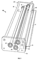
- Figure 3 is a perspective view of a sheet biasing apparatus.
- the apparatus 10 includes a media feed tray or shelf 20 from which individual media sheets are transported by suitable sheet moving apparatus (not shown) to be received in a nip or bight between opposed lamination rollers 50, 52.
- suitable sheet moving apparatus not shown
- opposed rollers may be replaced by equivalent means such as opposed belts therefore, in this disclosure and the claims, the terms “roller” and “rollers' are intended to broadly encompass ordinary rollers, plural coaxial wheels, moveable belts which are trained around rollers and other mechanical equivalents which perform the same function.
- a lamination stock supply reel 30 holds a wound web of layered material comprising a carrier 32 having a lamination coat 34 removably adhered to the carrier layer and adhesive 36 for bonding the lamination material to individual media sheets 38.
- the carrier 32 and lamination material as well as adhesive 36 are a clear plastic sheet material which adheres due to the adhesive to the laminated sheet from which the carrier 32 is then removed and would onto a take-up reel 40 after the media sheet 38 has been laminated.
- One or more guide rollers 42 serve to assist transport of the carrier 32 to the take-up reel 40.
- One or both of the lamination rollers 50, 52 may be heated to a temperature not exceeding about 160° C to simultaneously apply heat and pressure not exceeding about 4 lbs./sq. inch to the lamination web and media sheet 38 to bond the lamination coat 34 to the sheet 38.
- a carrier separator bar 80 is positioned downstream from the opposed lamination rollers 50, 52 and has a sharp edge or corner 54 around which the carrier 32 is bent during removal and transport of the carrier which is pulled by powered rotation of the take-up reel 40.
- a sheet biasing apparatus which may be a roller frame 60 comprised of spaced and pieces 62, 64 and transverse members 66, 68 affixed to the end pieces 62, 64.
- the frame supports the separator bar 80 and a feed lip or shelf 70 which, as shown, is part of transverse member 68, having an upper surface 72 generally aligned in the direction of media travel with the lowest corner of the separator bar 80 for receiving and guiding the laminated sheet 38 to the separator bar 80.
- media guide rollers 90, 92 and a deflector bar 94 all supported on the frame 60 together define a generally serpentine path through which the media must travel.
- the bend imparted to the media sheet transversely biases the moving media sheet such that the trailing edge of the sheet, upon passing by the separator bar 80 is caused to move in a direction generally transversely (upwardly or downwardly as shown, for example) to the path in which the media sheet passes the lower edge of the separator bar 82 because the trailing edge of the media sheet 38 resiliently straightens as it passes the separation corner on the separator bar 80 at which the carrier 32 also abruptly changes direction during passage to the take-up reel 40.
- the media sheet is bent in a direction to cause the trailing edge to deflect substantially upwardly parallel to the removed carrier 32. It is of course possible to orient the guide rollers 90, 92 and deflection bar 94 to bend the sheet such that the trailing edge resiliently straightens downwardly instead of upwardly away from the separation corner of the carrier bar 80 so that the trailing edge of the sheet deflects downwardly away from the removed carrier.
- the transverse bias is applied to the sheet by use of rollers 90, 92 and the deflection bar 94 but means other than rollers and a deflection bar for biasing the sheet in a direction substantially transverse to its path of movement can be envisioned.
- transversely extending blocks having a square or other angular configuration designed to urge the trailing edge of the media sheet 38 in a direction to effectuate a clean separation from the carrier 32 without trailing edge TAG.
- the deflection apparatus produces a transverse bend in the media sheet 38 which causes the trailing edge of the sheet to abruptly snap or move away from the corner of the separator bar 80 at which the carrier 32 is removed
- the inherent resilience of the laminated media sheet 38 causes an abrupt "snapping" action which substantially eliminates the objectionable trailing edge debris known as TAG.
Landscapes
- Engineering & Computer Science (AREA)
- Mechanical Engineering (AREA)
- Lining Or Joining Of Plastics Or The Like (AREA)
- Folding Of Thin Sheet-Like Materials, Special Discharging Devices, And Others (AREA)
Abstract
Description
Claims (16)
- A method of laminating sheets of media comprising the steps of:a) feeding a carrier (32) having a lamination coat (34) removably adhered thereon to a bight between opposed lamination rollers (50, 52);b) moving a sheet (38) of media to be laminated to said bight in surface to surface contact with said lamination coat;c) continuing to move said sheet and adhering said lamination coat to said sheet by application of pressure to said media and carrier by said opposed rollers;d) removing said carrier from a laminated sheet at a point (54) downstream of said rollers; ande) biasing said moving sheet (38) transversely to a direction of sheet movement to cause a trailing edge of said sheet to resiliently straighten and move away from said carrier as a trailing edge of said sheet passes said point.
- The method of claim 1, wherein said media sheet is biased in a direction to cause said trailing edge to deflect in a direction proximate a direction of movement of said removed carrier.
- The method of claim 1, wherein said media sheet is biased in a direction to cause said trailing edge to deflect in a direction substantially away from a direction of movement of said removed carrier.
- The method of claim 1, comprising holding said carrier in contact with said sheet moving in a first direction and pulling said carrier away from said sheet in a second direction which intersects said first direction at an exterior angle not less than about 85 °.
- The method of claim 4, comprising the step of using a rotating carrier take up roll (40) to pull said carrier in said second direction.
- The method of claim 5, including applying lamination pressure to said carrier and said sheet at said bight not exceeding about 4 lbs./sq. inch.
- The method of claim 6, further comprising the step of heating at least one of said rollers (50, 52) to a temperature not exceeding about 160° C during application of said pressure.
- Apparatus for laminating a sheet of media comprising:a) a support (20) for sheets of media to be laminated;b) a pair of opposed lamination rollers (50, 52) and means for rotating said lamination rollers to move a media sheet and a carrier having a lamination coat thereon in surface to surface contact with said sheet through a bight between said rollers;c) a carrier separator (80) for guiding movement of said carrier during removal of said carrier from a laminated sheet, said separator having a corner for holding said carrier in engagement with a laminated sheet;d) a puller for tensioning a carrier around said corner to remove a carrier from a laminated sheet; ande) a sheet guide (80, 90, 92, 94) to cause a trailing edge of a laminated sheet to resiliently deflect and separate from removed carrier.
- The apparatus of claim 8, wherein said sheet guide comprises spaced guides (80, 90) for bending a moving generally planar sheet transverse to the direction of movement of the sheet to urge a trailing edge of the sheet transversely of the plane of the sheet.
- The apparatus of claim 9, wherein said sheet guides include an angled surface positioned for engaging the leading edge of a sheet moving from said carrier separator.
- The apparatus of claim 10, wherein said angled surface is arcuate.
- The apparatus of claim 11, comprising a roller (90) positioned transversely to the direction of movement of a sheet, said arcuate surface being on said roller (90).
- The apparatus of claim 12, wherein said guides further comprise a second roller (92) and a curved guide (94) between said rollers.
- The apparatus of claim 10, wherein said puller comprises a rotatable carrier take up roll (40).
- The apparatus of claim 14, wherein said separator comprises a bar (80) extending parallel to said rollers (90, 92), said corner having an interior angle at said corner of not more than about 95°.
- The apparatus of claim 15, wherein said separator bar has a corner radius not exceeding about 0.50mm.
Applications Claiming Priority (2)
| Application Number | Priority Date | Filing Date | Title |
|---|---|---|---|
| US892217 | 1986-07-31 | ||
| US09/892,217 US6475322B1 (en) | 2001-06-25 | 2001-06-25 | Sheet lamination with transverse sheet bias to eliminate trailing edge coating debris |
Publications (2)
| Publication Number | Publication Date |
|---|---|
| EP1270212A2 true EP1270212A2 (en) | 2003-01-02 |
| EP1270212A3 EP1270212A3 (en) | 2004-01-02 |
Family
ID=25399572
Family Applications (1)
| Application Number | Title | Priority Date | Filing Date |
|---|---|---|---|
| EP02254277A Withdrawn EP1270212A3 (en) | 2001-06-25 | 2002-06-19 | Sheet lamination with transverse sheet bias to eliminate trailing edge coating debris |
Country Status (3)
| Country | Link |
|---|---|
| US (1) | US6475322B1 (en) |
| EP (1) | EP1270212A3 (en) |
| JP (1) | JP2003103634A (en) |
Families Citing this family (2)
| Publication number | Priority date | Publication date | Assignee | Title |
|---|---|---|---|---|
| US6732780B1 (en) * | 2002-10-25 | 2004-05-11 | Hewlett-Packard Development Company, L.P. | Print media coating device |
| DE102010053655A1 (en) * | 2010-12-07 | 2012-06-14 | Heidelberger Druckmaschinen Ag | Spot lamination with foil |
Family Cites Families (4)
| Publication number | Priority date | Publication date | Assignee | Title |
|---|---|---|---|---|
| US5169476A (en) * | 1991-11-27 | 1992-12-08 | Polaroid Corporation | Apparatus and method for delamination of a laminate |
| US5785795A (en) * | 1995-03-14 | 1998-07-28 | Polaroid Corporation | System and apparatus for delaminating a laminate containing image bearing media |
| JP3567714B2 (en) * | 1998-01-20 | 2004-09-22 | 富士ゼロックス株式会社 | Image forming material removal device |
| JP2001121609A (en) * | 1999-08-13 | 2001-05-08 | Canon Inc | Laminating method and laminating apparatus |
-
2001
- 2001-06-25 US US09/892,217 patent/US6475322B1/en not_active Expired - Fee Related
-
2002
- 2002-06-19 EP EP02254277A patent/EP1270212A3/en not_active Withdrawn
- 2002-06-25 JP JP2002184385A patent/JP2003103634A/en active Pending
Also Published As
| Publication number | Publication date |
|---|---|
| EP1270212A3 (en) | 2004-01-02 |
| US6475322B1 (en) | 2002-11-05 |
| JP2003103634A (en) | 2003-04-09 |
Similar Documents
| Publication | Publication Date | Title |
|---|---|---|
| TWI589507B (en) | Methods and apparatuses for applying a handling tab to continuous glass ribbons | |
| AU673526B2 (en) | Linerless label printer applicator | |
| KR20130099934A (en) | Sheet separation apparatus and separation method, and sheet attaching apparatus and attaching method | |
| JP2002522301A (en) | Apparatus and method for applying label without liner | |
| KR20150133755A (en) | Apparatus and method for processing lengths of flexible glass | |
| JP5684817B2 (en) | Labeling device | |
| JP5690573B2 (en) | Sheet peeling device | |
| US6475322B1 (en) | Sheet lamination with transverse sheet bias to eliminate trailing edge coating debris | |
| JP4302042B2 (en) | Film peeling device | |
| US10472190B2 (en) | Media handling system | |
| US6902643B2 (en) | Thermal transfer overcoat tag reduction | |
| US7005030B2 (en) | Printing and laminating apparatus | |
| JP4273023B2 (en) | Film sticking method and apparatus | |
| JP3025125B2 (en) | Punch separation method and punch separation apparatus | |
| CN108521770A (en) | Methods for gluing, handling and storing die-cut materials | |
| JP5929104B2 (en) | Label peeling mechanism, label peeling mechanism control method, and label printing apparatus | |
| EP1270213A2 (en) | Sheet lamination with angular separation of carrier | |
| CN215854292U (en) | Incoming material preprocessing device | |
| JP2013160961A (en) | Functional sheet sticking device and disposing method of defective portion of functional sheet in functional sheet sticking device | |
| JPWO2023248761A5 (en) | ||
| JP2008239283A (en) | Curing sheet applying device | |
| JP2016043631A (en) | Cutting device and cutting method | |
| JP2002321852A (en) | Web tailoring machine |
Legal Events
| Date | Code | Title | Description |
|---|---|---|---|
| PUAI | Public reference made under article 153(3) epc to a published international application that has entered the european phase |
Free format text: ORIGINAL CODE: 0009012 |
|
| AK | Designated contracting states |
Kind code of ref document: A2 Designated state(s): AT BE CH CY DE DK ES FI FR GB GR IE IT LI LU MC NL PT SE TR |
|
| AX | Request for extension of the european patent |
Free format text: AL;LT;LV;MK;RO;SI |
|
| PUAL | Search report despatched |
Free format text: ORIGINAL CODE: 0009013 |
|
| AK | Designated contracting states |
Kind code of ref document: A3 Designated state(s): AT BE CH CY DE DK ES FI FR GB GR IE IT LI LU MC NL PT SE TR |
|
| AX | Request for extension of the european patent |
Extension state: AL LT LV MK RO SI |
|
| 17P | Request for examination filed |
Effective date: 20040224 |
|
| AKX | Designation fees paid |
Designated state(s): DE FR GB NL |
|
| 17Q | First examination report despatched |
Effective date: 20041203 |
|
| 17Q | First examination report despatched |
Effective date: 20041203 |
|
| STAA | Information on the status of an ep patent application or granted ep patent |
Free format text: STATUS: THE APPLICATION IS DEEMED TO BE WITHDRAWN |
|
| 18D | Application deemed to be withdrawn |
Effective date: 20060919 |