EP1269081B1 - Utility lighter - Google Patents
Utility lighter Download PDFInfo
- Publication number
- EP1269081B1 EP1269081B1 EP01911060A EP01911060A EP1269081B1 EP 1269081 B1 EP1269081 B1 EP 1269081B1 EP 01911060 A EP01911060 A EP 01911060A EP 01911060 A EP01911060 A EP 01911060A EP 1269081 B1 EP1269081 B1 EP 1269081B1
- Authority
- EP
- European Patent Office
- Prior art keywords
- lighter
- producing apparatus
- button
- push
- wand
- Prior art date
- Legal status (The legal status is an assumption and is not a legal conclusion. Google has not performed a legal analysis and makes no representation as to the accuracy of the status listed.)
- Expired - Lifetime
Links
- 239000000446 fuel Substances 0.000 claims description 18
- 239000012530 fluid Substances 0.000 claims description 5
- 230000007246 mechanism Effects 0.000 description 18
- 235000021168 barbecue Nutrition 0.000 description 2
- 239000002184 metal Substances 0.000 description 2
- 238000012986 modification Methods 0.000 description 2
- 230000004048 modification Effects 0.000 description 2
- POIUWJQBRNEFGX-XAMSXPGMSA-N cathelicidin Chemical compound C([C@@H](C(=O)N[C@@H](CCCNC(N)=N)C(=O)N[C@@H](CCCCN)C(=O)N[C@@H](CO)C(=O)N[C@@H](CCCCN)C(=O)N[C@@H](CCC(O)=O)C(=O)N[C@@H](CCCCN)C(=O)N[C@@H]([C@@H](C)CC)C(=O)NCC(=O)N[C@@H](CCCCN)C(=O)N[C@@H](CCC(O)=O)C(=O)N[C@@H](CC=1C=CC=CC=1)C(=O)N[C@@H](CCCCN)C(=O)N[C@@H](CCCNC(N)=N)C(=O)N[C@@H]([C@@H](C)CC)C(=O)N[C@@H](C(C)C)C(=O)N[C@@H](CCC(N)=O)C(=O)N[C@@H](CCCNC(N)=N)C(=O)N[C@@H]([C@@H](C)CC)C(=O)N[C@@H](CCCCN)C(=O)N[C@@H](CC(O)=O)C(=O)N[C@@H](CC=1C=CC=CC=1)C(=O)N[C@@H](CC(C)C)C(=O)N[C@@H](CCCNC(N)=N)C(=O)N[C@@H](CC(N)=O)C(=O)N[C@@H](CC(C)C)C(=O)N[C@@H](C(C)C)C(=O)N1[C@@H](CCC1)C(=O)N[C@@H](CCCNC(N)=N)C(=O)N[C@@H]([C@@H](C)O)C(=O)N[C@@H](CCC(O)=O)C(=O)N[C@@H](CO)C(O)=O)NC(=O)[C@H](CC=1C=CC=CC=1)NC(=O)[C@H](CC(O)=O)NC(=O)CNC(=O)[C@H](CC(C)C)NC(=O)[C@@H](N)CC(C)C)C1=CC=CC=C1 POIUWJQBRNEFGX-XAMSXPGMSA-N 0.000 description 1
- 230000000994 depressogenic effect Effects 0.000 description 1
- 230000005611 electricity Effects 0.000 description 1
Images


Classifications
-
- F—MECHANICAL ENGINEERING; LIGHTING; HEATING; WEAPONS; BLASTING
- F23—COMBUSTION APPARATUS; COMBUSTION PROCESSES
- F23Q—IGNITION; EXTINGUISHING-DEVICES
- F23Q2/00—Lighters containing fuel, e.g. for cigarettes
- F23Q2/28—Lighters characterised by electrical ignition of the fuel
- F23Q2/285—Lighters characterised by electrical ignition of the fuel with spark ignition
- F23Q2/287—Lighters characterised by electrical ignition of the fuel with spark ignition piezoelectric
Definitions
- the present invention generally relates to general purpose utility lighters, such as those used to ignite candles, barbecue grills, fireplaces and campfires.
- Lighters such as those used for igniting purposes, for example, relying on a fuel container, have developed over a number of years. Typically, these lighters use either a rotary friction element or a piezoelectric ignition device to generate a spark in proximity to a nozzle emitting the fuel. Piezoelectric ignition devices have gained universal acceptance because they are simple to use. Such piezoelectric ignition devices are disclosed in U.S. patent No. 5,262,697 (the '697 patent) and JP-A-11 108 357 .
- Lighters have also evolved from the small pocket lighters to several forms of extended lighters that are more useful for general purposes, such as lighting candles, barbecue grills, fireplaces and campfires. Earlier attempts at such designs relied simply on extended actuating handles to house a typical lighter at the end. Examples of this design are found in U.S. patent Nos. 4,259,059 and 4,462,791 .
- shut-off mechanism for resisting undesired operation of the lighter by young children.
- these mechanisms take the form of on/off switches that may shut off the fuel source or may prevent movement of an actuator, such as a push-button, on the lighter.
- the on/off switches that must be affirmatively moved by the user between the "on” and “off” positions have drawbacks. For example, an adult user may forget to move the switch back to the "off” position after use, thereby allowing undesired operation.
- It is one object of this invention is to provide a utility lighter capable of resisting undesired operation.
- Another object of the invention is to incorporate a pocket lighter into a housing to form a utility lighter.
- Another object of the invention is to utilize the actuating mechanism of the pocket lighter as the actuating mechanism of the utility lighter.
- a further object of the invention is to utilize the child-resistant mechanism of the pocket lighter as the child-resistant mechanism of the utility lighter.
- Another object of the invention is to utilize the actuating mechanism and the child-resistant mechanism from the pocket lighter as the actuating trigger and the child-resistant mechanism of the utility lighter.
- the housing of the utility lighter may have any interchangeable aesthetically pleasing shape, so long as the housing is adapted to incorporate the pocket lighter.
- a flame producing apparatus comprising a body connected to a wand, said body containing a preassembled lighter comprising a piezoelectric ignition device and a fuel source in fluid communication with a valve movable between a closed position and an open position, a latch member movable between a position where the lighter is inoperative and a position where the lighter is operative; an inner tube disposed within the wand, where said valve and ignition device are actuatable by a push-button to selectively release fuel and to produce a spark, and said inner tube is in fluid communication with the valve of the lighter and a nozzle, and wherein the wand and the inner tube are electrically coupled to the ignition device such that the spark is produced proximate the nozzle when the ignition device is actuated, characterized in that said body is a casing for a utility lighter and defines a cut-out portion, where the cut-out portion is sized and dimensioned to expose the push-button and the latch member for
- the lighter is preferably a child-resistant lighter, which may comprise a latch member movable between an inoperative position where the latch member interferes with the actuation of the push-button and an operative position where the latch member does not interfere with the push-button. In the inoperative position, the latch member is positioned between the push-button and the lighter housing to interfere with the actuation of the push-button. Furthermore, the body of the flame producing apparatus may also define a second cut-out portion sized and dimensioned to expose the latch member of the child-resistant lighter for user actuation.
- FIGS 1-5 generally describe the first embodiment of utility lighter 10 in accordance to the present invention.
- Lighter 10 comprises a housing 12, a conductive wand 14, and a pocket lighter 16.
- the pocket lighter 16 is sized and dimensioned to be inserted into the housing 12.
- An end cap 18 is adapted to fit into the back end of housing 12 to retain pocket lighter 16 inside the housing.
- the housing may be formed from two equal halves.
- pocket lighter 16 is substantially a standard piezoelectric lighter, which comprises a housing 20 containing a fuel reservoir, a piezoelectric element 22 and a push-button 24.
- the term lighter refers to any lighter, which has at least a fuel reservoir, a piezoelectric element and a push-button, and is capable of producing a flame.
- the fuel reservoir is in fluid communication with a gas valve 26, which preferably includes a valve and a movable jet. Valve 26 is movable between an open position and a closed position to selectively release fuel.
- the piezoelectric element 22 is preferably connected to push-button 24, such that when a user pushes the push-button the piezoelectric element 22 is compressed to produce an electrical charge.
- the electrical charge is conducted to electrode 28 and to valve 26, or a conductive diffuser spring attached to valve 26, to generate a spark therebetween.
- the push-button compresses the piezoelectric element 22, the push-button also acts on biased pivotal arm 30, which is operatively connected to valve 26 to lift the valve to selectively release fuel to be ignited by the spark generated across the gap between the valve 26 and the electrode 28.
- Pocket lighter 16, as described thus far, is substantially similar to the lighter illustrated in the '697 patent and in U.S. patent No. 5,854,530 .
- an elongated fuel conduit 32 is connected to gas valve 26 at one end to communicate the fuel released from pocket lighter 16 to the front end of the wand 14.
- Conduit 32 can be either rigid or flexible and terminates at a nozzle 34, which may include a diffuser spring, at the opposite end.
- conduit 32 can have any shape or configuration as long as it communicates the fuel released from valve 26 to nozzle 34, and conducts the electricity from valve 26 or the diffuser spring attached thereto to nozzle 34.
- conduit 32 may be constructed from an electrically conductive metal or a pliable conductive rubber.
- Conduit 32 may also comprise a conductive member, such as a metal wire, disposed inside an insulated tube.
- the conductive member may be embedded within the wall of the insulated tube.
- the conductive member may also be a portion of the wall of the insulated tube.
- the conductive member may comprise a plurality of wires disposed either inside the tube or within the wall of the tube.
- the conductive member can also be a mesh or woven wire or a conductive tube disposed concentrically with respect to the insulated tube.
- an insulated conductive wire may be used, as illustrated in U.S. patent No. 5,934,895 .
- the insulated wire can be positioned.inside or outside of the conduit.
- the wind guard on the lighter is removed before the conduit is connected to the valve.
- the pocket lighter and the conduit are then inserted into the housing 12 and electrically conductive wand 14, as illustrated in Figs. 2-4.
- wand 14 has extension 36 which is disposed within the housing 12.
- Electrode 28 of pocket lighter 16 is sized and dimensioned to maintain sliding contact with extension 36 when the piezoelectric element is being compressed, such that the electrical charge from electrode 28 is conducted through wand 14 to front electrode 38.
- electrode 28 is in contact with extension 36 when the electrical charge is generated.
- conduit 32 and nozzle 34 are preferably electrically conductive to communicate the electrical charge from valve 26 to nozzle 34. The spark generated between nozzle 34 and front electrode 38 would ignite the fuel released from nozzle 34 to produce a flame.
- a hollow insulated sleeve 40 is disposed between wand 14 and nozzle to prevent the spark from occurring anywhere except between nozzle 34 and front electrode 38.
- the housing 12 may extend to the front end of the lighter and wand 14 can be disposed on the outside of the extended portion of the housing. In this case, the extended portion of the housing electrically insulated the conductive wand from the conduit 32.
- Pocket lighter 16 also a latch which acts as comprises a child-resistant mechanism, said latch 42 disposed between the push-button 24 and housing 20 of the pocket lighter.
- Latch 42 is biased by a spring 44 to an inoperative position, where it prevents the actuation of the push-button, as shown in Fig. 3.
- a user may move latch 42 against the biasing force of spring 44 to an operative position, where actuation of the push-button is allowed.
- movement of latch 42 in the inward direction, i.e ., toward the valve 26 places the lighter 16 in the operative position.
- Further upward movement of latch 42, i.e., toward push-button 24 temporarily holds latch 42 in the operative position.
- spring 44 biases the latch 42 back to the inoperative position.
- latch 42 as illustrated herein are fully described in U.S. patent Nos. 5,445,518 and 5,584,682 .
- Other piezoelectric child-resistant lighters with a child-resistant latch can be used in conjunction with the utility lighter 10 of the present invention.
- the piezoelectric lighters with child-resistant latch disclosed in, but not limited to, U.S. patent Nos. 5,531,591 , 5,458,482 , 5,240,408 , 5,145,358 , 4,904,180 , 5,462,432 , 5,788,476 , 5,839,892 , 4,904,180 , and 5,228,849 are usable in the present invention.
- lighters can also be used, as long as it has a piezoelectric mechanism actuatable by a push-button.
- the push-button may also be a single trigger, or the push-button may comprise a gas release member and a separate a spark generating member.
- Housing 12 has a first cut-out portion 46 sized and positioned to allow the push-button or the push-button and/or latch to expose therethrough for user manipulation. Housing 12 preferably has a second cut-out portion 48 sized and positioned to allow the latch to expose therethrough. Second cut-out portion 48 is not required when utility lighter 10 is used with a latch-less child-resistant piezoelectric lighter or when the latch is located on the push-button. Cut-outs 46 and 48 are illustrated herein to be proximate to each other. However, cut-outs 46 and 48 can be located anywhere on housing 12 to accommodate the push-button and/or latch on the various pocket lighters.
- the operation of the utility lighter 10 of the present invention is substantially identical to the operation of the pocket lighter 16 contained therein, i.e., the user operates the utility lighter the same way that the user would operate the pocket lighter.
- One of the advantages of the present invention is that the ignition mechanism and/or the child-resistant mechanism of the pocket lighter become the ignition mechanism and/or child-resistant mechanism of the utility lighter.
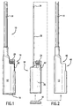
- FIG. 6-10 A second embodiment of the utility lighter is shown in Figs. 6-10, where wand 50 is shown.
- Wand 50 has extension 52 which defines a slot 54, as shown in Fig. 10(b).
- Electrode 28 of lighter 16 is movably received in slot 54 to maintain electrical contact between electrode 28 and wand 50 when push-button compresses piezoelectric element 22 to generate a spark.
- a hook 56 is optionally provided.
- the lighter 16 is illustrated in Fig. 2 without a wind shield, which normally surrounds valve 26.
- a wind shield may be incorporated to the lighter 16 without departing from the present invention.
- housing 12 it is well within the purview of one of ordinary skills in this art to modify the shape of housing 12 to any aesthetically pleasing shape, as long as the housing is sized and dimensioned to receive a lighter such as lighter 16.
Description
- The present invention generally relates to general purpose utility lighters, such as those used to ignite candles, barbecue grills, fireplaces and campfires.
- Lighters such as those used for igniting purposes, for example, relying on a fuel container, have developed over a number of years. Typically, these lighters use either a rotary friction element or a piezoelectric ignition device to generate a spark in proximity to a nozzle emitting the fuel. Piezoelectric ignition devices have gained universal acceptance because they are simple to use. Such piezoelectric ignition devices are disclosed in
U.S. patent No. 5,262,697 (the '697 patent) andJP-A-11 108 357 - Lighters have also evolved from the small pocket lighters to several forms of extended lighters that are more useful for general purposes, such as lighting candles, barbecue grills, fireplaces and campfires. Earlier attempts at such designs relied simply on extended actuating handles to house a typical lighter at the end. Examples of this design are found in
U.S. patent Nos. 4,259,059 and4,462,791 . - In addition, many of the general purpose lighters have had some form of shut-off mechanism for resisting undesired operation of the lighter by young children. Often, these mechanisms take the form of on/off switches that may shut off the fuel source or may prevent movement of an actuator, such as a push-button, on the lighter. Moreover, the on/off switches that must be affirmatively moved by the user between the "on" and "off" positions have drawbacks. For example, an adult user may forget to move the switch back to the "off" position after use, thereby allowing undesired operation.
- One solution that overcomes the drawback of a user forgetting to return the on/off switch to the off position is to utilize a biased latch that only allows operation of the lighter when the latch is moved into a position out of interference with the valve actuator. Once the valve actuator is depressed and released, the latch returns to its inoperative or latched position automatically so that subsequent use of the lighter again requires moving the latch out of interference with the valve actuator. Examples of such a device are found in
U.S. patent Nos. 5,445,518 and5,584,682 . - Other utility lighters incorporate a pocket lighter only as a fuel source and have an actuating trigger and child-resistant mechanism, in addition to the pocket lighter's actuating mechanism. An example of this design is illustrated in
GB 2,156,499A - There remains a need for a utility lighter that can directly utilize the fuel, the push-button and/or child-resistant mechanism from a pocket lighter.
- It is one object of this invention is to provide a utility lighter capable of resisting undesired operation.
- Another object of the invention is to incorporate a pocket lighter into a housing to form a utility lighter.
- Another object of the invention is to utilize the actuating mechanism of the pocket lighter as the actuating mechanism of the utility lighter.
- A further object of the invention is to utilize the child-resistant mechanism of the pocket lighter as the child-resistant mechanism of the utility lighter.
- Another object of the invention is to utilize the actuating mechanism and the child-resistant mechanism from the pocket lighter as the actuating trigger and the child-resistant mechanism of the utility lighter.
- Another advantage of the invention is that the housing of the utility lighter may have any interchangeable aesthetically pleasing shape, so long as the housing is adapted to incorporate the pocket lighter.
- These objects and advantages and other objects and advantage are accomplished in a flame producing apparatus comprising a body connected to a wand, said body containing a preassembled lighter comprising a piezoelectric ignition device and a fuel source in fluid communication with a valve movable between a closed position and an open position, a latch member movable between a position where the lighter is inoperative and a position where the lighter is operative; an inner tube disposed within the wand, where said valve and ignition device are actuatable by a push-button to selectively release fuel and to produce a spark, and said inner tube is in fluid communication with the valve of the lighter and a nozzle, and wherein the wand and the inner tube are electrically coupled to the ignition device such that the spark is produced proximate the nozzle when the ignition device is actuated, characterized in that said body is a casing for a utility lighter and defines a cut-out portion, where the cut-out portion is sized and dimensioned to expose the push-button and the latch member for user actuation when the lighter is received inside the body, and the latch member interferes with the actuation of the push-button in the position where the preassembled lighter is inoperative and does not interfere with the push-button in the position where the preassembled lighter is operative.
- The lighter is preferably a child-resistant lighter, which may comprise a latch member movable between an inoperative position where the latch member interferes with the actuation of the push-button and an operative position where the latch member does not interfere with the push-button. In the inoperative position, the latch member is positioned between the push-button and the lighter housing to interfere with the actuation of the push-button. Furthermore, the body of the flame producing apparatus may also define a second cut-out portion sized and dimensioned to expose the latch member of the child-resistant lighter for user actuation.
- To facilitate the understanding of the characteristics of this invention, the following drawing figures have been provided, wherein:
- Fig. 1 is a front view of a first embodiment of a utility lighter of the present invention;
- Fig. 2 is an exploded view of the utility lighter of Fig. 1;
- Fig. 3 is a partial cross-sectional view of the utility lighter of Fig. 1 showing the utility lighter in the inoperative position;
- Fig. 4 is a partial cross-sectional view of the utility lighter of Fig. 1 showing the utility lighter in the operative position;
- Fig. 5(a) is a front view of a conductive shell, and Fig. 5(b) is a partial top view of the conductive shell;
- Fig. 6 is a front view of a second embodiment of a utility lighter of the present invention;
- Fig. 7 is a side view of the utility lighter of Fig. 6;
- Fig. 8 is a partial cross-sectional view of the utility lighter of Fig. 6 showing the lighter in the operative position;
- Fig. 9 is an end view of the utility lighter of Fig. 6; and
- Fig. 10(a) is a front view of another conductive shell and Fig.10(b) is a partial perspective view of an end of the conductive shell.
- Figures 1-5 generally describe the first embodiment of utility lighter 10 in accordance to the present invention. Lighter 10 comprises a
housing 12, aconductive wand 14, and apocket lighter 16. The pocket lighter 16 is sized and dimensioned to be inserted into thehousing 12. Anend cap 18 is adapted to fit into the back end ofhousing 12 to retain pocket lighter 16 inside the housing. Alternatively, the housing may be formed from two equal halves. - As illustrated,
pocket lighter 16 is substantially a standard piezoelectric lighter, which comprises ahousing 20 containing a fuel reservoir, apiezoelectric element 22 and a push-button 24. As used herein, the term lighter refers to any lighter, which has at least a fuel reservoir, a piezoelectric element and a push-button, and is capable of producing a flame. The fuel reservoir is in fluid communication with agas valve 26, which preferably includes a valve and a movable jet. Valve 26 is movable between an open position and a closed position to selectively release fuel. Thepiezoelectric element 22 is preferably connected to push-button 24, such that when a user pushes the push-button thepiezoelectric element 22 is compressed to produce an electrical charge. In thepocket lighter 16, the electrical charge is conducted toelectrode 28 and tovalve 26, or a conductive diffuser spring attached tovalve 26, to generate a spark therebetween. As the push-button compresses thepiezoelectric element 22, the push-button also acts on biasedpivotal arm 30, which is operatively connected tovalve 26 to lift the valve to selectively release fuel to be ignited by the spark generated across the gap between thevalve 26 and theelectrode 28.Pocket lighter 16, as described thus far, is substantially similar to the lighter illustrated in the '697 patent and inU.S. patent No. 5,854,530 . - As shown in Fig. 2, an
elongated fuel conduit 32 is connected togas valve 26 at one end to communicate the fuel released frompocket lighter 16 to the front end of thewand 14.Conduit 32 can be either rigid or flexible and terminates at anozzle 34, which may include a diffuser spring, at the opposite end. Furthermore,conduit 32 can have any shape or configuration as long as it communicates the fuel released fromvalve 26 tonozzle 34, and conducts the electricity fromvalve 26 or the diffuser spring attached thereto tonozzle 34. For example,conduit 32 may be constructed from an electrically conductive metal or a pliable conductive rubber.Conduit 32 may also comprise a conductive member, such as a metal wire, disposed inside an insulated tube. Alternatively, the conductive member may be embedded within the wall of the insulated tube. The conductive member may also be a portion of the wall of the insulated tube. The conductive member may comprise a plurality of wires disposed either inside the tube or within the wall of the tube. Additionally, the conductive member can also be a mesh or woven wire or a conductive tube disposed concentrically with respect to the insulated tube. These shapes and configurations are known in the art and are illustrated inEP 222 336 A1 U.S. patent No. 5,934,895 . Of course, the insulated wire can be positioned.inside or outside of the conduit. - Preferably, the wind guard on the lighter is removed before the conduit is connected to the valve. The pocket lighter and the conduit are then inserted into the
housing 12 and electricallyconductive wand 14, as illustrated in Figs. 2-4. As shown in Figs. 3, 4, 5(a) and 5(b),wand 14 hasextension 36 which is disposed within thehousing 12.Electrode 28 of pocket lighter 16 is sized and dimensioned to maintain sliding contact withextension 36 when the piezoelectric element is being compressed, such that the electrical charge fromelectrode 28 is conducted throughwand 14 tofront electrode 38. Preferably,electrode 28 is in contact withextension 36 when the electrical charge is generated. On the other hand, as discussed aboveconduit 32 andnozzle 34 are preferably electrically conductive to communicate the electrical charge fromvalve 26 tonozzle 34. The spark generated betweennozzle 34 andfront electrode 38 would ignite the fuel released fromnozzle 34 to produce a flame. - Preferably, a hollow
insulated sleeve 40, as shown in Figs. 3 and 4, is disposed betweenwand 14 and nozzle to prevent the spark from occurring anywhere except betweennozzle 34 andfront electrode 38. Alternatively, as shown in the '895 patent, thehousing 12 may extend to the front end of the lighter andwand 14 can be disposed on the outside of the extended portion of the housing. In this case, the extended portion of the housing electrically insulated the conductive wand from theconduit 32. - Pocket lighter 16 also a latch which acts as comprises a child-resistant mechanism, said
latch 42 disposed between the push-button 24 andhousing 20 of the pocket lighter.Latch 42 is biased by aspring 44 to an inoperative position, where it prevents the actuation of the push-button, as shown in Fig. 3. A user may movelatch 42 against the biasing force ofspring 44 to an operative position, where actuation of the push-button is allowed. For the exemplary lighter 16 illustrated in Fig. 3, movement oflatch 42 in the inward direction, i.e., toward thevalve 26, places the lighter 16 in the operative position. Further upward movement oflatch 42, i.e., toward push-button 24, temporarily holdslatch 42 in the operative position. After the user depresses and releases the push-button,spring 44 biases thelatch 42 back to the inoperative position. - The structure and operation of
latch 42 as illustrated herein are fully described inU.S. patent Nos. 5,445,518 and5,584,682 . Other piezoelectric child-resistant lighters with a child-resistant latch can be used in conjunction with the utility lighter 10 of the present invention. For example, the piezoelectric lighters with child-resistant latch disclosed in, but not limited to,U.S. patent Nos. 5,531,591 ,5,458,482 ,5,240,408 ,5,145,358 ,4,904,180 ,5,462,432 ,5,788,476 ,5,839,892 ,4,904,180 , and5,228,849 are usable in the present invention. Other lighters can also be used, as long as it has a piezoelectric mechanism actuatable by a push-button. The push-button may also be a single trigger, or the push-button may comprise a gas release member and a separate a spark generating member. -
Housing 12 has a first cut-outportion 46 sized and positioned to allow the push-button or the push-button and/or latch to expose therethrough for user manipulation.Housing 12 preferably has a second cut-outportion 48 sized and positioned to allow the latch to expose therethrough. Second cut-outportion 48 is not required when utility lighter 10 is used with a latch-less child-resistant piezoelectric lighter or when the latch is located on the push-button. Cut-outs outs housing 12 to accommodate the push-button and/or latch on the various pocket lighters. - The operation of the utility lighter 10 of the present invention is substantially identical to the operation of the pocket lighter 16 contained therein, i.e., the user operates the utility lighter the same way that the user would operate the pocket lighter. One of the advantages of the present invention is that the ignition mechanism and/or the child-resistant mechanism of the pocket lighter become the ignition mechanism and/or child-resistant mechanism of the utility lighter.
- A second embodiment of the utility lighter is shown in Figs. 6-10, where
wand 50 is shown.Wand 50 hasextension 52 which defines aslot 54, as shown in Fig. 10(b).Electrode 28 of lighter 16 is movably received inslot 54 to maintain electrical contact betweenelectrode 28 andwand 50 when push-button compressespiezoelectric element 22 to generate a spark. Ahook 56 is optionally provided. - While it is apparent that the invention herein disclosed is well calculated to fulfill the objects above stated, it will be appreciated that numerous modifications and embodiments may be devised by those skilled in the art, and it is intended that the appended claims cover all such modifications and embodiments as fall within the scope of the present invention. For example, the lighter 16 is illustrated in Fig. 2 without a wind shield, which normally surrounds
valve 26. A wind shield may be incorporated to the lighter 16 without departing from the present invention. Furthermore, while one particular shape ofhousing 12 is illustrated, it is well within the purview of one of ordinary skills in this art to modify the shape ofhousing 12 to any aesthetically pleasing shape, as long as the housing is sized and dimensioned to receive a lighter such as lighter 16.
Claims (12)
- A flame producing apparatus (10) comprising:a body (12) connected to a wand (14), said body (12) containing a preassembled lighter (16), comprising a piezoelectric ignition device (22) and a fuel source in fluid communication with a valve (26) movable between a closed position and an open position, a latch member (42) movable between a position where the lighter is inoperative and a position where the lighter is operative; an inner tube (32) disposed within the wand (14), where said valve (26) and ignition device (22) are actuatable by a push-button (24) to selectively release fuel and to produce a spark, and said inner tube (32) is in fluid communication with the valve (26) of the preassembled lighter (16) and a nozzle (34), and wherein the wand (14) and the inner tube (32) are electrically coupled to the ignition device (22) such that the spark is produced proximate the nozzle (34) when the ignition device (22) is actuated, wherebysaid body (12) is a casing for a utility lighter and defines a cut-out portion (46, 48), where the cut-out portion (46, 48) is sized and dimensioned to expose the push-button (24) and the latch member (42) for user actuation when the preassembled lighter (16) is received inside the body (12), andthe latch member (42) interferes with the actuation of the push-button (24) in the position where the preassembled lighter (16) is inoperative and does not interfere with the push-button (24) in the position where the preassembled lighter (16) is operative.
- The flame producing apparatus (10) of claim 1 further comprises an end cap (18) adapted to fit on to a first end of the body (12) to retain the lighter (16) within the body (12).
- The flame producing apparatus (10) of claim 2, wherein the nozzle (34) is located at a second end of the inner tube (32) remote from said first end of the body (12).
- The flame producing apparatus (10) of claim 1, wherein the piezoelectric ignition device (22) comprises first and second electrodes (28), said first electrode is electrically coupled to the wand (14) and the second electrode is electrically coupled to the inner tube (32).
- The flame producing apparatus (10) of claim 4 further comprises an extension (36), which electrically couples the wand (14) to the first electrode (28).
- The flame producing apparatus (10) of claim 4, wherein the extension (36) is integral with the wand (14).
- The flame producing apparatus (10) of claim 5, wherein the first electrode (28) is slidingly connected to the wand (14).
- The flame producing apparatus (10) of claim 5, wherein the first electrode (28) is slidingly connected to the extension (36).
- The flame producing apparatus (10) of claim 5, wherein the first electrode (28) is movably received in a channel defined by the extension (36).
- The flame producing apparatus (10) of claim 1, wherein the inner tube (32) is rigid.
- The flame producing apparatus (10) of claim 1, wherein the inner tube (32) is flexible.
- The flame producing apparatus (10) of claim 1, wherein in the inoperative position the latch member (42) is positioned between the push-button (24) and the body (12).
Applications Claiming Priority (3)
| Application Number | Priority Date | Filing Date | Title |
|---|---|---|---|
| US510304 | 1990-04-16 | ||
| US09/510,304 US6428309B1 (en) | 2000-02-22 | 2000-02-22 | Utility lighter |
| PCT/US2001/005538 WO2001063179A1 (en) | 2000-02-22 | 2001-02-21 | Utility lighter |
Publications (3)
| Publication Number | Publication Date |
|---|---|
| EP1269081A1 EP1269081A1 (en) | 2003-01-02 |
| EP1269081A4 EP1269081A4 (en) | 2005-03-02 |
| EP1269081B1 true EP1269081B1 (en) | 2007-08-08 |
Family
ID=24030206
Family Applications (1)
| Application Number | Title | Priority Date | Filing Date |
|---|---|---|---|
| EP01911060A Expired - Lifetime EP1269081B1 (en) | 2000-02-22 | 2001-02-21 | Utility lighter |
Country Status (14)
| Country | Link |
|---|---|
| US (1) | US6428309B1 (en) |
| EP (1) | EP1269081B1 (en) |
| JP (1) | JP3936194B2 (en) |
| CN (1) | CN1218142C (en) |
| AR (1) | AR027954A1 (en) |
| AU (2) | AU2001238601B2 (en) |
| BR (1) | BR0108569B1 (en) |
| CA (1) | CA2400932C (en) |
| DE (1) | DE60129802T2 (en) |
| ES (1) | ES2291299T3 (en) |
| MX (1) | MXPA02008094A (en) |
| MY (1) | MY119971A (en) |
| TW (1) | TWI247088B (en) |
| WO (1) | WO2001063179A1 (en) |
Families Citing this family (10)
| Publication number | Priority date | Publication date | Assignee | Title |
|---|---|---|---|---|
| US6644958B1 (en) * | 2002-05-06 | 2003-11-11 | Kin Chung Li | Barbecue lighter with safety arrangement |
| US6926519B1 (en) * | 2003-01-29 | 2005-08-09 | Gregory Lusson | Lighter extension assembly |
| US8653942B2 (en) | 2008-08-20 | 2014-02-18 | John Gibson Enterprises, Inc. | Portable biometric lighter |
| US9964305B1 (en) | 2016-01-19 | 2018-05-08 | Peter Brady | Campfire lighter |
| WO2018108254A1 (en) * | 2016-12-13 | 2018-06-21 | SOCIéTé BIC | Flame producing assembly and method for manufacturing such a flame producing assembly |
| US11112112B2 (en) * | 2016-12-13 | 2021-09-07 | Societe Bic | Flame producing assembly and method for manufacturing such a flame producing assembly |
| US10502419B2 (en) | 2017-09-12 | 2019-12-10 | John Gibson Enterprises, Inc. | Portable biometric lighter |
| CN111561708A (en) * | 2019-02-14 | 2020-08-21 | 约翰吉布森企业有限公司 | Igniter system with replaceable combustible fuel tank |
| US11933493B2 (en) * | 2021-01-22 | 2024-03-19 | Pro-Iroda Industries, Inc. | Tool with improved ignition efficiency |
| US11852342B2 (en) * | 2021-01-22 | 2023-12-26 | Pro-Iroda Industries, Inc. | Tool with improved ignition efficiency |
Family Cites Families (62)
| Publication number | Priority date | Publication date | Assignee | Title |
|---|---|---|---|---|
| US2679740A (en) * | 1951-09-04 | 1954-06-01 | Constantin C Seletzky | Stand for pocket lighters |
| US3544252A (en) | 1968-07-31 | 1970-12-01 | Ronson Corp | Combination pocket and table lighter |
| US3580983A (en) | 1969-12-03 | 1971-05-25 | Nat Catheter Corp | Conductive line tube |
| US4133450A (en) * | 1977-06-14 | 1979-01-09 | Bic Pen Corporation | Table lighter device |
| FR2399619A1 (en) * | 1977-08-03 | 1979-03-02 | Siot Taillefer Paul | Cigarette lighter for table use - has lighter unit fitting into body of separate holder with top pushbutton to operate flame action |
| US4222734A (en) * | 1978-09-29 | 1980-09-16 | Nolf Roland S | Remote lighting device |
| US4253820A (en) * | 1979-05-10 | 1981-03-03 | Jarreau Donald J | Fireplace lighter |
| US4259059A (en) | 1979-08-15 | 1981-03-31 | Roosa Vernon D | Extension lighter |
| US4389187A (en) | 1981-03-16 | 1983-06-21 | Sims Michael H | Extended holder for a lighter |
| US4462791A (en) | 1982-08-30 | 1984-07-31 | Richard Hayden | Fire lighter |
| DE3332335A1 (en) * | 1983-09-08 | 1985-03-28 | Ludwig Dipl.-Ing. Lang | Protective cap for a disposable cigarette lighter |
| GB2156499A (en) | 1984-03-28 | 1985-10-09 | Freezinhot Bottle Co Limited | Domestic ignitors |
| CH664208A5 (en) * | 1984-05-26 | 1988-02-15 | Attila Janos Tibor Horvath Dr | Gas lighter flame-offsetting equipment - comprises small metal tube fitted over nozzle with extension wire for ignition |
| US4522583A (en) * | 1984-05-31 | 1985-06-11 | Kraser Gary S | Cigarette lighter |
| US4640679A (en) * | 1984-10-15 | 1987-02-03 | Denis Perrin | Flame shield for cigarette lighter and cigarette lighter including said flame shield |
| DE8436764U1 (en) * | 1984-12-15 | 1985-03-14 | Consuma AG, Balzers | HAND GAS LIGHTER |
| JPS6281858U (en) | 1985-11-12 | 1987-05-25 | ||
| JPH053897Y2 (en) | 1988-06-07 | 1993-01-29 | ||
| US4799877A (en) | 1988-06-13 | 1989-01-24 | Bisbee Jerry L | Child-proof adaptor for disposable butane cigarette lighter |
| US5445518A (en) | 1988-09-02 | 1995-08-29 | Bic Corporation | Selectively actuatable lighter |
| US5584682A (en) | 1988-09-02 | 1996-12-17 | Bic Corporation | Selectively actuatable lighter with anti-defeat latch |
| US4901848A (en) | 1988-11-09 | 1990-02-20 | Parren Joseph R | Case for personal accessory items |
| ES2016143A6 (en) * | 1989-06-19 | 1990-10-16 | Laforest Sa | Safety mechanisms for lighters |
| JPH0492142U (en) | 1990-11-30 | 1992-08-11 | ||
| EP0516858B1 (en) * | 1990-11-30 | 1996-01-31 | Tokai Corporation | Ignition device |
| US5082440A (en) | 1990-12-27 | 1992-01-21 | Shin Fuji Burner Co., Ltd. | Handy compact torch |
| FR2674004B1 (en) | 1991-03-13 | 1995-12-08 | Laforest Bic Sa | PIEZOELECTRIC MECHANISM FOR GAS LIGHTERS. |
| FR2675885B1 (en) | 1991-04-24 | 1993-07-16 | Cricket Sa | LIGHTER WITH LIGHTING CONTROL BY SLIDING MEMBER, CHILD-PROOF. |
| JP2784977B2 (en) | 1992-01-13 | 1998-08-13 | 株式会社東海 | Gas lighter with safety device |
| US5222889A (en) | 1992-08-05 | 1993-06-29 | Chein Sheng Machine Industrial Co., Ltd. | Electronic igniter |
| JPH06307638A (en) * | 1993-04-20 | 1994-11-01 | Masayuki Iwabori | Extended ignition device for piezoelectric ignition gas lighter |
| US5304060A (en) | 1993-04-30 | 1994-04-19 | Lin Arlo H T | Handy torch |
| EP0660046B1 (en) * | 1993-12-22 | 1999-12-01 | Siemens Westinghouse Power Corporation | Combustor bybass system for a gas turbine |
| JPH07190355A (en) | 1993-12-27 | 1995-07-28 | Fuji Kaken:Kk | Pocket lighter |
| US5531592A (en) | 1994-02-28 | 1996-07-02 | Tasi; Chin-Lin | Handy gas torch |
| JP2784145B2 (en) | 1994-03-03 | 1998-08-06 | 株式会社東海 | Gas lighter with safety device |
| US5462432A (en) | 1994-06-17 | 1995-10-31 | Kim; Jin K. | Gas lighter with ignition safety device |
| JP3110951B2 (en) | 1994-10-12 | 2000-11-20 | 株式会社東海 | Ignition rod safety device |
| US5505614A (en) | 1994-08-22 | 1996-04-09 | Lin; Arlo H. T. | Handy gas torch |
| US5460520A (en) | 1994-09-28 | 1995-10-24 | Lin; H. T. Arlo | Trigger-controlled palm-top gas torch |
| US5479914A (en) * | 1994-12-06 | 1996-01-02 | Tsai; Chin-Lin | Internal combustion glue gun |
| US5513980A (en) | 1995-03-03 | 1996-05-07 | Rasmussen; Clair L. | Method and apparatus to override the child-resistant mechanism of disposable lighters |
| US5531591A (en) | 1995-03-17 | 1996-07-02 | Tokai Corporation | Safety device for use in lighter |
| US5667377A (en) | 1995-07-07 | 1997-09-16 | Lin; Arlo H. T. | Gas torch |
| WO1997006388A1 (en) * | 1995-08-04 | 1997-02-20 | Koo Jin Wan | Lighter with position-adjustable flame nozzle |
| JP3516153B2 (en) | 1995-11-09 | 2004-04-05 | 株式会社東海 | Gas igniter |
| FR2743867B1 (en) | 1996-01-24 | 1998-03-27 | Cricket Sa | LIGHTER ACTUATED BY A LONGITUDINALLY MOVABLE PUSH BUTTON, CHILD-PROOF |
| US5839892A (en) | 1996-03-26 | 1998-11-24 | Hwang; Ing Feng | Electronic lighter with a safety device |
| US5788476A (en) | 1996-04-30 | 1998-08-04 | Polycity Industrial Ltd | Childproof piezoelectric lighter with sliding mechanism |
| US5800155A (en) | 1996-06-27 | 1998-09-01 | Miyanaga; Tsuneo | Flame torch |
| US5854530A (en) | 1996-12-18 | 1998-12-29 | Bic Corporation | Piezoelectric lighter which has a higher level of difficulty for operation |
| US5934895A (en) | 1997-01-22 | 1999-08-10 | Bic Corporation | Utility lighter |
| US5741128A (en) | 1997-08-21 | 1998-04-21 | Tsai; Chin-Lin | Hand gas torch |
| US5833448A (en) | 1997-09-02 | 1998-11-10 | Bic Corporation | Child resistant lighter |
| JP3553773B2 (en) | 1997-09-30 | 2004-08-11 | 岩堀 雅行 | Ignition device |
| US5921768A (en) * | 1997-10-03 | 1999-07-13 | Joncg; T. | Flame torch |
| US5901881A (en) * | 1998-02-12 | 1999-05-11 | Chen Chu Li Su | Multipurpose glue gun |
| US5885070A (en) | 1998-07-16 | 1999-03-23 | Lin; Arlo H. T. | Gas control mechanism |
| US5996243A (en) * | 1998-09-18 | 1999-12-07 | Chang; Chih-Chang | Hair dryer |
| US6010328A (en) * | 1999-03-26 | 2000-01-04 | Sung; Kil Yong | Double-trigger child-resistant utility lighter |
| US6077071A (en) * | 1999-11-26 | 2000-06-20 | Yeh; Chun Ching | Safety apparatus of barbecue lighter |
| US6086359A (en) * | 1999-12-13 | 2000-07-11 | Polycity Enterprise Limited | Lighter with a safety system |
-
2000
- 2000-02-22 US US09/510,304 patent/US6428309B1/en not_active Expired - Lifetime
-
2001
- 2001-02-21 JP JP2001562108A patent/JP3936194B2/en not_active Expired - Lifetime
- 2001-02-21 EP EP01911060A patent/EP1269081B1/en not_active Expired - Lifetime
- 2001-02-21 ES ES01911060T patent/ES2291299T3/en not_active Expired - Lifetime
- 2001-02-21 MX MXPA02008094A patent/MXPA02008094A/en active IP Right Grant
- 2001-02-21 CA CA2400932A patent/CA2400932C/en not_active Expired - Lifetime
- 2001-02-21 AU AU2001238601A patent/AU2001238601B2/en not_active Ceased
- 2001-02-21 CN CN01808456.7A patent/CN1218142C/en not_active Expired - Lifetime
- 2001-02-21 BR BRPI0108569-7A patent/BR0108569B1/en not_active IP Right Cessation
- 2001-02-21 DE DE60129802T patent/DE60129802T2/en not_active Expired - Lifetime
- 2001-02-21 AU AU3860101A patent/AU3860101A/en active Pending
- 2001-02-21 WO PCT/US2001/005538 patent/WO2001063179A1/en active IP Right Grant
- 2001-02-21 MY MYPI20010749A patent/MY119971A/en unknown
- 2001-02-22 AR ARP010100816A patent/AR027954A1/en active IP Right Grant
- 2001-03-20 TW TW090104064A patent/TWI247088B/en not_active IP Right Cessation
Also Published As
| Publication number | Publication date |
|---|---|
| CA2400932C (en) | 2010-05-11 |
| JP2003524141A (en) | 2003-08-12 |
| WO2001063179A1 (en) | 2001-08-30 |
| CN1426520A (en) | 2003-06-25 |
| MY119971A (en) | 2005-08-30 |
| AU3860101A (en) | 2001-09-03 |
| MXPA02008094A (en) | 2003-05-23 |
| DE60129802D1 (en) | 2007-09-20 |
| BR0108569A (en) | 2003-12-23 |
| CN1218142C (en) | 2005-09-07 |
| ES2291299T3 (en) | 2008-03-01 |
| AR027954A1 (en) | 2003-04-16 |
| US6428309B1 (en) | 2002-08-06 |
| DE60129802T2 (en) | 2008-04-24 |
| AU2001238601B2 (en) | 2004-06-03 |
| EP1269081A4 (en) | 2005-03-02 |
| JP3936194B2 (en) | 2007-06-27 |
| BR0108569B1 (en) | 2010-10-19 |
| EP1269081A1 (en) | 2003-01-02 |
| CA2400932A1 (en) | 2001-08-30 |
| TWI247088B (en) | 2006-01-11 |
Similar Documents
| Publication | Publication Date | Title |
|---|---|---|
| US6095799A (en) | Utility lighter | |
| RU2230990C2 (en) | Multi-purpose lighter | |
| EP1269081B1 (en) | Utility lighter | |
| EP1212568B1 (en) | Utility lighter | |
| ES2310994T3 (en) | UTILITY LIGHTER. | |
| AU2001238601A1 (en) | Utility lighter | |
| EP0975918B1 (en) | Utility lighter | |
| JP2003524141A5 (en) | ||
| JPH0412360Y2 (en) | ||
| AU2003203484B2 (en) | Utility lighter | |
| AU756146B2 (en) | Utility lighter | |
| CA2467273C (en) | Utility lighter | |
| JPH01314813A (en) | Ignitor | |
| CZ294770B6 (en) | Utility lighter |
Legal Events
| Date | Code | Title | Description |
|---|---|---|---|
| PUAI | Public reference made under article 153(3) epc to a published international application that has entered the european phase |
Free format text: ORIGINAL CODE: 0009012 |
|
| 17P | Request for examination filed |
Effective date: 20020905 |
|
| AK | Designated contracting states |
Kind code of ref document: A1 Designated state(s): AT BE CH CY DE DK ES FI FR GB GR IE IT LI LU MC NL PT SE TR |
|
| AX | Request for extension of the european patent |
Free format text: AL;LT;LV;MK;RO;SI |
|
| RIN1 | Information on inventor provided before grant (corrected) |
Inventor name: DOIRON, GERALD, J. |
|
| RBV | Designated contracting states (corrected) |
Designated state(s): DE ES FR GB |
|
| A4 | Supplementary search report drawn up and despatched |
Effective date: 20050114 |
|
| RAP1 | Party data changed (applicant data changed or rights of an application transferred) |
Owner name: BIC CORPORATION |
|
| GRAP | Despatch of communication of intention to grant a patent |
Free format text: ORIGINAL CODE: EPIDOSNIGR1 |
|
| GRAS | Grant fee paid |
Free format text: ORIGINAL CODE: EPIDOSNIGR3 |
|
| GRAA | (expected) grant |
Free format text: ORIGINAL CODE: 0009210 |
|
| AK | Designated contracting states |
Kind code of ref document: B1 Designated state(s): DE ES FR GB |
|
| REG | Reference to a national code |
Ref country code: GB Ref legal event code: FG4D |
|
| REF | Corresponds to: |
Ref document number: 60129802 Country of ref document: DE Date of ref document: 20070920 Kind code of ref document: P |
|
| REG | Reference to a national code |
Ref country code: ES Ref legal event code: FG2A Ref document number: 2291299 Country of ref document: ES Kind code of ref document: T3 |
|
| ET | Fr: translation filed | ||
| PLBE | No opposition filed within time limit |
Free format text: ORIGINAL CODE: 0009261 |
|
| STAA | Information on the status of an ep patent application or granted ep patent |
Free format text: STATUS: NO OPPOSITION FILED WITHIN TIME LIMIT |
|
| 26N | No opposition filed |
Effective date: 20080509 |
|
| PGFP | Annual fee paid to national office [announced via postgrant information from national office to epo] |
Ref country code: ES Payment date: 20120227 Year of fee payment: 12 |
|
| REG | Reference to a national code |
Ref country code: ES Ref legal event code: FD2A Effective date: 20141010 |
|
| PG25 | Lapsed in a contracting state [announced via postgrant information from national office to epo] |
Ref country code: ES Free format text: LAPSE BECAUSE OF NON-PAYMENT OF DUE FEES Effective date: 20130222 |
|
| REG | Reference to a national code |
Ref country code: FR Ref legal event code: PLFP Year of fee payment: 15 |
|
| REG | Reference to a national code |
Ref country code: FR Ref legal event code: PLFP Year of fee payment: 16 |
|
| REG | Reference to a national code |
Ref country code: FR Ref legal event code: PLFP Year of fee payment: 17 |
|
| REG | Reference to a national code |
Ref country code: FR Ref legal event code: PLFP Year of fee payment: 18 |
|
| PGFP | Annual fee paid to national office [announced via postgrant information from national office to epo] |
Ref country code: GB Payment date: 20200123 Year of fee payment: 20 Ref country code: DE Payment date: 20200121 Year of fee payment: 20 |
|
| PGFP | Annual fee paid to national office [announced via postgrant information from national office to epo] |
Ref country code: FR Payment date: 20200122 Year of fee payment: 20 |
|
| REG | Reference to a national code |
Ref country code: DE Ref legal event code: R071 Ref document number: 60129802 Country of ref document: DE |
|
| REG | Reference to a national code |
Ref country code: GB Ref legal event code: PE20 Expiry date: 20210220 |
|
| PG25 | Lapsed in a contracting state [announced via postgrant information from national office to epo] |
Ref country code: GB Free format text: LAPSE BECAUSE OF EXPIRATION OF PROTECTION Effective date: 20210220 |