EP1268742B1 - Perfusion incubator - Google Patents
Perfusion incubator Download PDFInfo
- Publication number
- EP1268742B1 EP1268742B1 EP01922798A EP01922798A EP1268742B1 EP 1268742 B1 EP1268742 B1 EP 1268742B1 EP 01922798 A EP01922798 A EP 01922798A EP 01922798 A EP01922798 A EP 01922798A EP 1268742 B1 EP1268742 B1 EP 1268742B1
- Authority
- EP
- European Patent Office
- Prior art keywords
- well
- fluid
- assembly
- specimen
- inlet
- Prior art date
- Legal status (The legal status is an assumption and is not a legal conclusion. Google has not performed a legal analysis and makes no representation as to the accuracy of the status listed.)
- Expired - Lifetime
Links
Images

Classifications
-
- C—CHEMISTRY; METALLURGY
- C12—BIOCHEMISTRY; BEER; SPIRITS; WINE; VINEGAR; MICROBIOLOGY; ENZYMOLOGY; MUTATION OR GENETIC ENGINEERING
- C12M—APPARATUS FOR ENZYMOLOGY OR MICROBIOLOGY; APPARATUS FOR CULTURING MICROORGANISMS FOR PRODUCING BIOMASS, FOR GROWING CELLS OR FOR OBTAINING FERMENTATION OR METABOLIC PRODUCTS, i.e. BIOREACTORS OR FERMENTERS
- C12M3/00—Tissue, human, animal or plant cell, or virus culture apparatus
- C12M3/02—Tissue, human, animal or plant cell, or virus culture apparatus with means providing suspensions
-
- C—CHEMISTRY; METALLURGY
- C12—BIOCHEMISTRY; BEER; SPIRITS; WINE; VINEGAR; MICROBIOLOGY; ENZYMOLOGY; MUTATION OR GENETIC ENGINEERING
- C12M—APPARATUS FOR ENZYMOLOGY OR MICROBIOLOGY; APPARATUS FOR CULTURING MICROORGANISMS FOR PRODUCING BIOMASS, FOR GROWING CELLS OR FOR OBTAINING FERMENTATION OR METABOLIC PRODUCTS, i.e. BIOREACTORS OR FERMENTERS
- C12M21/00—Bioreactors or fermenters specially adapted for specific uses
- C12M21/06—Bioreactors or fermenters specially adapted for specific uses for in vitro fertilization
-
- C—CHEMISTRY; METALLURGY
- C12—BIOCHEMISTRY; BEER; SPIRITS; WINE; VINEGAR; MICROBIOLOGY; ENZYMOLOGY; MUTATION OR GENETIC ENGINEERING
- C12M—APPARATUS FOR ENZYMOLOGY OR MICROBIOLOGY; APPARATUS FOR CULTURING MICROORGANISMS FOR PRODUCING BIOMASS, FOR GROWING CELLS OR FOR OBTAINING FERMENTATION OR METABOLIC PRODUCTS, i.e. BIOREACTORS OR FERMENTERS
- C12M23/00—Constructional details, e.g. recesses, hinges
- C12M23/02—Form or structure of the vessel
- C12M23/12—Well or multiwell plates
-
- C—CHEMISTRY; METALLURGY
- C12—BIOCHEMISTRY; BEER; SPIRITS; WINE; VINEGAR; MICROBIOLOGY; ENZYMOLOGY; MUTATION OR GENETIC ENGINEERING
- C12M—APPARATUS FOR ENZYMOLOGY OR MICROBIOLOGY; APPARATUS FOR CULTURING MICROORGANISMS FOR PRODUCING BIOMASS, FOR GROWING CELLS OR FOR OBTAINING FERMENTATION OR METABOLIC PRODUCTS, i.e. BIOREACTORS OR FERMENTERS
- C12M23/00—Constructional details, e.g. recesses, hinges
- C12M23/22—Transparent or translucent parts
-
- C—CHEMISTRY; METALLURGY
- C12—BIOCHEMISTRY; BEER; SPIRITS; WINE; VINEGAR; MICROBIOLOGY; ENZYMOLOGY; MUTATION OR GENETIC ENGINEERING
- C12M—APPARATUS FOR ENZYMOLOGY OR MICROBIOLOGY; APPARATUS FOR CULTURING MICROORGANISMS FOR PRODUCING BIOMASS, FOR GROWING CELLS OR FOR OBTAINING FERMENTATION OR METABOLIC PRODUCTS, i.e. BIOREACTORS OR FERMENTERS
- C12M29/00—Means for introduction, extraction or recirculation of materials, e.g. pumps
- C12M29/10—Perfusion
-
- C—CHEMISTRY; METALLURGY
- C12—BIOCHEMISTRY; BEER; SPIRITS; WINE; VINEGAR; MICROBIOLOGY; ENZYMOLOGY; MUTATION OR GENETIC ENGINEERING
- C12M—APPARATUS FOR ENZYMOLOGY OR MICROBIOLOGY; APPARATUS FOR CULTURING MICROORGANISMS FOR PRODUCING BIOMASS, FOR GROWING CELLS OR FOR OBTAINING FERMENTATION OR METABOLIC PRODUCTS, i.e. BIOREACTORS OR FERMENTERS
- C12M41/00—Means for regulation, monitoring, measurement or control, e.g. flow regulation
- C12M41/12—Means for regulation, monitoring, measurement or control, e.g. flow regulation of temperature
- C12M41/14—Incubators; Climatic chambers
Definitions
- This invention relates to incubators and more particularly incubators for cell culturing, in particular culturing embryos of mammalian species.
- Some cells growing in a liquid medium produce exogenous and growth factors which surround the cell in the liquid medium. In the growing of such cells in vitro it is important not to immediately flush these exogenous and growth factors when changing the medium around the cell.
- embryos means non human embryos.
- the invention is said to reside in a perfusion incubator, including a fluid supply, a fluid conditioning unit, at least one well assembly and a well assembly heating unit, a pump such as a peristaltic pump, and preferably a fluid collection unit, the well assembly including at least one well, each well having a fluid inlet and a fluid outlet, each fluid inlet being positioned at a point in the well above the cell and each fluid outlet being positioned above its respective fluid inlet above the cell (such as an embryo) to be cultured in a lower portion of the well, the fluid inlet connected to the fluid supply and the fluid outlet connected to the fluid collection unit via the peristaltic pump whereby on the placing of the specimen cell to be cultured in each well and flowing fluid through the well, culturing of the cell can occur.
- a perfusion incubator including a fluid supply, a fluid conditioning unit, at least one well assembly and a well assembly heating unit, a pump such as a peristaltic pump, and preferably a fluid collection unit
- the well assembly including at
- an illumination device so that the cell being cultured in the well assembly can be observed by means of a microscope.
- a microscope mount associate with the perfusion incubator.
- Each well may include means to provide a flow path from the fluid inlet to the fluid outlet within the well so that fluid flow is not directly around the cell in the well.
- each fluid inlet is positioned so as to allow a tangential entry of fluid to the well at a mid point in the well, and the fluid outlet being positioned above the fluid inlet with the cell to be cultured in a lower portion of the well, whereby flow of fluid in the well is formed by this construction into a vortex which will tend to draw fluid from around the cell without direct flow over the cell.
- Each well can have a stepped side wall defining an upper chamber and a smaller lower chamber with a lid which in use is adapted to extend partially into the upper chamber.
- Each lid may be made of a substantially transparent material so as to allow for viewing of the cell in the lower chamber.
- the well assembly may be transparent so that the cell can be illuminated from below.
- the peristaltic pump can provide a flow rate of fluid through each well of between 40 microlitres per hour up to 4000 microlitres per hour when in flush mode.
- the fluid conditioning unit may be operated at a temperature of approximately 0.5°C above the operating temperature of the well assembly heating unit whereby increase in solubility of gases in the fluid because of the 0.5°C temperature drop upon entry into a well, and decrease in solubility because of reduced pressure in the well due to suction of the peristaltic pump, are both compensated for and gas bubbles do not form in the culture well.
- the invention is said to reside in a perfusion incubator well assembly having a body, at least one well in the body, the or each well having a stepped side well defining an upper chamber and a smaller lower chamber and a lid, a fluid inlet to the or each well and fluid outlet from the or each well, the fluid inlet being positioned so as to allow tangential entry of fluid to the well at a lower portion of the upper chamber and the fluid outlet being positioned above the fluid inlet.
- a well closure such as a lid may be adapted to extend partially into the upper chamber, and may include an O-ring seal and be made of a substantially transparent material so as to allow viewing of an cell in the lower chamber.
- the body may be made from a substantially transparent material so that with illumination from below, the cell being cultured can be viewed.
- the fluid inlet and the fluid outlet to the or each well may be formed by apertures formed in the body.
- the perfusion incubator is a system which based on the principle of perfusion of specifically designed culture fluid, provides a suitable environment for the production, development and storage of pre-implantation embryos from mammalian species.
- the system maintains purpose-built culture wells at a pre-set temperature while perfusing carbon dioxide enriched culture media over the cells.
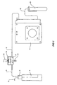
- FIG. 1 shows a schematic view of a perfusion incubator according to the present invention
- FIG. 2 shows an isometric view of a perfusion incubator
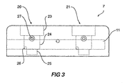
- FIG. 3 shows a cross sectional view of a culture chamber for the perfusion incubator
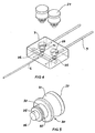
- FIG. 4 shows an isometric view of a well assembly
- FIG. 5 shows an isometric view of the lid for the culture chamber.
- the perfusion incubator includes a fluid heater unit 1 which has a gas inlet 2, the peristaltic pump 4 draws fluid from test tube 5 in the fluid heater unit through fluid inlet line 6, through the chamber 7 (as will be discussed in detail below) through the fluid outlet line 9 and after the peristaltic pump 4, travels through line 10 into fluid collection unit 11.
- an illumination source 13 Above the chambers is a chamber heater unit 14 and above this is a microscope lens 15. The microscope lens is held in microscope holder 16 as can be seen in Figure 2 . In Figure 2 the chamber heater unit 14 has been raised so that the chambers below it can be seen.
- the chamber 7 has a first well generally shown as 20 and a second well generally shown as 21.
- Each well has a stepped cross section with at least two sections generally, and as shown, may have a largest upper section 23 into which the lid fits, a middle section 24 and a smallest lower section 35.
- the fluid inlet 26 to each well is preferably at the bottom of the middle section 24 and the fluid outlet 27 is preferably at the top of the middle section 24.
- a cell to be cultured is placed in the lower section 25.
- the well closure such as lid 30, as can be seen in Figures 4 and 5 , has an upper portion 31 to enable placement and removal of the lid and is of a size which can be gripped by the fingers.
- a central portion 32 of the lid is adapted to fit into the upper section 23 of the well with an O-ring in the slot 33 providing sealing of the lid.
- the lower portion 35 of the lid is adapted in use to fit into the middle section 24 of the well but allows fluid to flow around it towards the fluid outlet 27.
- the lower surface 26 of the lid 30 and the upper surface 37 are both finely polished so that viewing through the lid enables viewing of the cell being cultured in the lower section of the well.
- the well can have the lid system described, but if an annular region is required to assist with the tangential flow, then a coaxial tube could be fitted in the well, and the lid can be replaced by a simple seal enabling the specimen or cell structure to be positioned in the lower chamber.
- the sides of the well can be curved if that would improve the tangential flow of the fluid and the formation of the vortex.
- the perfusion incubator according to the invention is constructed and operated as discussed below.
- the tube heater will preferably contain at least six tubes containing culture fluid which may or may not be the same as that in other tubes.
- the fluid or media is held at the user's specified temperature and equilibrated with specific gas mixtures capable of maintaining the required pH in the culture media.
- Each pair of culture wells is connected by non-toxic, non-permeable tubing to a tube of media in the front, and to a peristaltic pump in the rear of the culture wells. Whilst it is preferred to use a peristaltic pump, an ordinary continuous pump could alternatively be employed. It could be located in the supply line or the exhaust line, although the latter is preferred. From the peristaltic pump the tubing continues to the media waste receiver tubes, where used media is collected as waste or for further analysis. The peristaltic pump draws solution from the heated reservoirs through the culture wells to the waste containers. The whole process of temperature, light and fluid flow control may be maintained by a microprocessor.
- each culture well itself may be made of plastic materials such as polycarbonate and have highly polished surfaces.
- Underneath each culture well is a high output light emitting diode.
- a set of 5 pairs of culture wells may be contained in a heating block. In operation mode the chamber in the heater until which is contained in the lid, is placed down over the culture wells. In the lid is a clear glass strip. Above the heater block is a microscope holder. With a microscope in place and the light emitting diode beneath the culture well turned on, an operator is able to observe the embryos directly in situ .
- a motor driven system to position the microscope over each culture well may be used.
- the motor driven system may be provided to position the microscope over each consecutive culture well, for instance, at one minute intervals which would make it possible to accumulate digital time lapse photography of growth patterns of individual embryos in each culture well.
- the illumination beneath each culture well may one be turned on as required to capture an image.
- Light output from an LED is specifically in the orange-yellow band to be of low energy but provide high contrast.
- the light emitting source contains no ultra-violet radiation as this may damage the embryos.
- Embryos for culture are placed in the bottom of the culture well where they stick in the margin between the horizontal and vertical axes of the lower section. The embryos are not dislodged by the action of culture media flowing across them.
- Culture media is introduced above the lower section as a tangential flow to the inner surface of the culture well and removed from the top of the well. This creates an upward moving vortex which displaces media in the lower section of the culture well. Without this vortex action, media exchange in the bottom section of the well is by diffusion only, which results in embryo death or at best, embryos with very poor morphology which would not be suitable for implantation.
- a particular feature of the culture wells is the vortex action to exchange media in the bottom section. This action can be observed by the injection of small amounts of dye and following the fluid path.
- the embryos Once the embryos are ready for implantation they can be perfused with cryo-protectant and the whole block can be frozen in liquid nitrogen.
Abstract
Description
- This invention relates to incubators and more particularly incubators for cell culturing, in particular culturing embryos of mammalian species.
- Some cells growing in a liquid medium produce exogenous and growth factors which surround the cell in the liquid medium. In the growing of such cells in vitro it is important not to immediately flush these exogenous and growth factors when changing the medium around the cell.
- It is the object of this invention to provide an incubator well for the growing of cells such as embryos which have favorable growing conditions. Throughout the description, the term embryos means non human embryos.
- The invention is said to reside in a perfusion incubator, including a fluid supply, a fluid conditioning unit, at least one well assembly and a well assembly heating unit, a pump such as a peristaltic pump, and preferably a fluid collection unit, the well assembly including at least one well, each well having a fluid inlet and a fluid outlet, each fluid inlet being positioned at a point in the well above the cell and each fluid outlet being positioned above its respective fluid inlet above the cell (such as an embryo) to be cultured in a lower portion of the well, the fluid inlet connected to the fluid supply and the fluid outlet connected to the fluid collection unit via the peristaltic pump whereby on the placing of the specimen cell to be cultured in each well and flowing fluid through the well, culturing of the cell can occur.
- There may be further included an illumination device so that the cell being cultured in the well assembly can be observed by means of a microscope. There may be further included a microscope mount associate with the perfusion incubator.
- Each well may include means to provide a flow path from the fluid inlet to the fluid outlet within the well so that fluid flow is not directly around the cell in the well.
- Preferably, each fluid inlet is positioned so as to allow a tangential entry of fluid to the well at a mid point in the well, and the fluid outlet being positioned above the fluid inlet with the cell to be cultured in a lower portion of the well, whereby flow of fluid in the well is formed by this construction into a vortex which will tend to draw fluid from around the cell without direct flow over the cell.
- Each well can have a stepped side wall defining an upper chamber and a smaller lower chamber with a lid which in use is adapted to extend partially into the upper chamber.
- Each lid may be made of a substantially transparent material so as to allow for viewing of the cell in the lower chamber.
- The well assembly may be transparent so that the cell can be illuminated from below.
- The peristaltic pump can provide a flow rate of fluid through each well of between 40 microlitres per hour up to 4000 microlitres per hour when in flush mode.
- The fluid conditioning unit may be operated at a temperature of approximately 0.5°C above the operating temperature of the well assembly heating unit whereby increase in solubility of gases in the fluid because of the 0.5°C temperature drop upon entry into a well, and decrease in solubility because of reduced pressure in the well due to suction of the peristaltic pump, are both compensated for and gas bubbles do not form in the culture well.
- In an alternate form the invention is said to reside in a perfusion incubator well assembly having a body, at least one well in the body, the or each well having a stepped side well defining an upper chamber and a smaller lower chamber and a lid, a fluid inlet to the or each well and fluid outlet from the or each well, the fluid inlet being positioned so as to allow tangential entry of fluid to the well at a lower portion of the upper chamber and the fluid outlet being positioned above the fluid inlet.
- A well closure such as a lid may be adapted to extend partially into the upper chamber, and may include an O-ring seal and be made of a substantially transparent material so as to allow viewing of an cell in the lower chamber.
- The body may be made from a substantially transparent material so that with illumination from below, the cell being cultured can be viewed.
- The fluid inlet and the fluid outlet to the or each well may be formed by apertures formed in the body.
- It can be seen, therefore, that by this invention the perfusion incubator is a system which based on the principle of perfusion of specifically designed culture fluid, provides a suitable environment for the production, development and storage of pre-implantation embryos from mammalian species. The system maintains purpose-built culture wells at a pre-set temperature while perfusing carbon dioxide enriched culture media over the cells.
- This very generally describes the invention but to assist with understanding, reference will now be made to the accompanying drawings which show a preferred embodiment of the invention.
-
FIG. 1 shows a schematic view of a perfusion incubator according to the present invention,
FIG. 2 shows an isometric view of a perfusion incubator,
FIG. 3 shows a cross sectional view of a culture chamber for the perfusion incubator,
FIG. 4 shows an isometric view of a well assembly; and
FIG. 5 shows an isometric view of the lid for the culture chamber. - Now looking at the drawings in detail we see that the perfusion incubator includes a fluid heater unit 1 which has a
gas inlet 2, the peristaltic pump 4 draws fluid fromtest tube 5 in the fluid heater unit throughfluid inlet line 6, through the chamber 7 (as will be discussed in detail below) through thefluid outlet line 9 and after the peristaltic pump 4, travels throughline 10 intofluid collection unit 11. - The
fluid flow lines Figure 2 . - Below the
chamber 7 is anillumination source 13. Above the chambers is achamber heater unit 14 and above this is amicroscope lens 15. The microscope lens is held inmicroscope holder 16 as can be seen inFigure 2 . InFigure 2 thechamber heater unit 14 has been raised so that the chambers below it can be seen. - As can be seen in the side view in
Figure 3 , thechamber 7 has a first well generally shown as 20 and a second well generally shown as 21. Each well has a stepped cross section with at least two sections generally, and as shown, may have a largestupper section 23 into which the lid fits, amiddle section 24 and a smallestlower section 35. Thefluid inlet 26 to each well is preferably at the bottom of themiddle section 24 and thefluid outlet 27 is preferably at the top of themiddle section 24. In use, a cell to be cultured is placed in thelower section 25. The well closure such aslid 30, as can be seen inFigures 4 and 5 , has anupper portion 31 to enable placement and removal of the lid and is of a size which can be gripped by the fingers. Acentral portion 32 of the lid is adapted to fit into theupper section 23 of the well with an O-ring in theslot 33 providing sealing of the lid. Thelower portion 35 of the lid is adapted in use to fit into themiddle section 24 of the well but allows fluid to flow around it towards thefluid outlet 27. Thelower surface 26 of thelid 30 and theupper surface 37 are both finely polished so that viewing through the lid enables viewing of the cell being cultured in the lower section of the well. - The well can have the lid system described, but if an annular region is required to assist with the tangential flow, then a coaxial tube could be fitted in the well, and the lid can be replaced by a simple seal enabling the specimen or cell structure to be positioned in the lower chamber. The sides of the well can be curved if that would improve the tangential flow of the fluid and the formation of the vortex.
- In a preferred embodiment, the perfusion incubator according to the invention is constructed and operated as discussed below.
- The tube heater will preferably contain at least six tubes containing culture fluid which may or may not be the same as that in other tubes. The fluid or media is held at the user's specified temperature and equilibrated with specific gas mixtures capable of maintaining the required pH in the culture media.
- Each pair of culture wells is connected by non-toxic, non-permeable tubing to a tube of media in the front, and to a peristaltic pump in the rear of the culture wells. Whilst it is preferred to use a peristaltic pump, an ordinary continuous pump could alternatively be employed. It could be located in the supply line or the exhaust line, although the latter is preferred. From the peristaltic pump the tubing continues to the media waste receiver tubes, where used media is collected as waste or for further analysis. The peristaltic pump draws solution from the heated reservoirs through the culture wells to the waste containers. The whole process of temperature, light and fluid flow control may be maintained by a microprocessor.
- In a preferred embodiment the culture wells themselves may be made of plastic materials such as polycarbonate and have highly polished surfaces. Underneath each culture well is a high output light emitting diode. A set of 5 pairs of culture wells may be contained in a heating block. In operation mode the chamber in the heater until which is contained in the lid, is placed down over the culture wells. In the lid is a clear glass strip. Above the heater block is a microscope holder. With a microscope in place and the light emitting diode beneath the culture well turned on, an operator is able to observe the embryos directly in situ.
- It is useful in growing a healthy embryo to observe the growth pattern. A motor driven system to position the microscope over each culture well may be used.
- The motor driven system may be provided to position the microscope over each consecutive culture well, for instance, at one minute intervals which would make it possible to accumulate digital time lapse photography of growth patterns of individual embryos in each culture well. The illumination beneath each culture well may one be turned on as required to capture an image. Light output from an LED is specifically in the orange-yellow band to be of low energy but provide high contrast. In addition to this, it is preferable the light emitting source contains no ultra-violet radiation as this may damage the embryos.
- Embryos for culture are placed in the bottom of the culture well where they stick in the margin between the horizontal and vertical axes of the lower section. The embryos are not dislodged by the action of culture media flowing across them. Culture media is introduced above the lower section as a tangential flow to the inner surface of the culture well and removed from the top of the well. This creates an upward moving vortex which displaces media in the lower section of the culture well. Without this vortex action, media exchange in the bottom section of the well is by diffusion only, which results in embryo death or at best, embryos with very poor morphology which would not be suitable for implantation. A particular feature of the culture wells is the vortex action to exchange media in the bottom section. This action can be observed by the injection of small amounts of dye and following the fluid path.
- The reason that the embryos are not placed directly in the fluid path is that exogenous and growth factors excreted by the embryos would be flushed away immediately. By placing in a lower section where the media exchange rate is less than the true flow rate, then the exogenous and growth factors remain in the proximity of the embryos for at least a short time.
- In operation mode, with the lids in place, there is a negative pressure of approximately 1 kPa within the culture well as media is being pulled through by the peristaltic pump. This slight negative pressure may cause outgassing of the dissolved gasses which maintain the pH of the culture media. Henry's Law states that the mass of gas dissolved by a given volume of solvent at a constant temperature is proportional to the pressure of the gas in equilibrium with the solvent. Small bubbles which form in the culture well may isolate embryos from culture media with resultant death of the embryos. These minute bubbles cannot be dislodged at the flow rates used in this device. The flow rate used per well can vary between 40 microlitres per hour up to 4000 microlitres per hour when in flush mode.
- To overcome this bubble problem, media at 0.5°C above the operating temperature of the culture chamber is equilibrated with gas mixture. As gases dissolve with the liberation of heat the Le Chatelier principle dictates that a rise in temperature will cause a decrease in gas solubility. Equilibrating the culture media at 0.5°C above the chamber temperature with the gas mixture prior to the media's entry into the culture well, ensures that the increase in solubility because of the 0.5°C temperature drop and decrease in solubility because of the 1 kPa pressure drop are both compensated for and no gas bubbles form in the culture well. Without the pre-equilibration of the media at the higher temperature, the culture well may not perform effectively.
- Once the embryos are ready for implantation they can be perfused with cryo-protectant and the whole block can be frozen in liquid nitrogen.
- Throughout this specification and the claims that follow unless the context requires otherwise, the words 'comprise' and 'include' and variations such as 'comprising' and 'including' will be understood to imply the inclusion of a stated integer or group of integers but not the exclusion of any other integer or group of integers.
Claims (14)
- A perfusion incubator well assembly (7) having a body with at least one well (20,21) therein, the well having an upper section (23) and a lower section (25), the latter serving to receive a specimen to be cultured, and a part (30) for permitting the specimen to be positioned in the well, wherein the well (20,21) has a fluid inlet (26) for permitting fluid to enter the well at a location above the position at which the specimen is to be located, the well (20,21) also having a fluid outlet (27) positioned above the fluid inlet (26), and wherein either the inlet (26) or the shape of the well, or both, ensure tangential flow of the fluid.
- The assembly (7) according to claim 1, wherein the upper section (23) has an annular region for containing the said tangential flow.
- The assembly (7) according to claim 2, wherein the said part (30) is a sealable lid for the well (20,21), and wherein the lid has a portion (35) extendable into the well (20,21) to form the said annular region, and/or wherein the inlet (26) and/or outlet (27) are formed by apertures in the body.
- The assembly (7) according to claim 3, wherein the upper part of the lid and the lower part of the said portion are of transparent material, and/or wherein the body in the region of the specimen location is of transparent material, said transparent material(s) enabling observation of the specimen.
- The assembly (7) according to claim 1, 2, 3 or 4, wherein the or each well (20,21) has a stepped side wall defining the upper section (23) and the lower section (25) which is smaller than the upper section.
- The assembly (7) according to any one preceding claim, wherein the said inlet (26) is positioned so as to allow a tangential entry of fluid to the middle region of the well whereby flow of fluid in the well (20,21) is formed into a vortex which will tend to draw fluid from around the specimen without direct flow over the specimen.
- Perfusion incubator apparatus comprising the assembly (7) of any one preceding claim and further comprising an input arrangement for supplying the fluid to the said inlet (26), and an output arrangement for removing fluid from the outlet (27).
- Apparatus according to claim 7, wherein the output arrangement has a pump (4) for assisting with the removal of fluid from the said outlet (27).
- Apparatus according to claim 7 or 8, wherein the pump is a peristaltic pump (4) to provide a flow rate of fluid through each well of between 40 microlitres per hour and 4000 microlitres per hour when in flush mode.
- Apparatus according to claim 7, 8 or 9, further including an illumination device (13) so that the specimen being cultured in the well assembly (7) can be observed by means of a microscope, and further including a microscope mount (16) for a microscope.
- Apparatus according to claim 7, 8, 9 or 10, wherein the fluid is to be heated to a temperature of approximately 0.5°C above the operating temperature of the well assembly (7) to provide an increase in solubility of gases in the fluid because of the 0.5°C temperature drop upon entry into a well (20,21), and a decrease in solubility because of suction of the peristaltic pump (4), both being compensated for without gas bubbles being formed in the culture well.
- An incubator, including means (12) for supplying fluid to the incubator, at least one well assembly (7) and a well assembly heating unit (14), a peristaltic pump (4) and a fluid collection unit (11), the well assembly (7) including a plurality of wells (20,21), each having a fluid inlet (26) and a fluid outlet (27), each fluid inlet being positioned generally in a midsection (24) in the well and each fluid outlet (27) being positioned above its respective fluid inlet (26), with the cell to be cultured to be positioned in a lower section (25) of the well, the fluid inlet (26) connected to the fluid supply and the fluid outlet (27) connected to the fluid collection unit via the peristaltic pump whereby on the placing of a cell to be cultured in each well (20,21) and flowing fluid through the well culturing of the cell can occur.
- A method of incubating a cell specimen with the exception of a human embryo in a well assembly (7), comprising the steps of placing the cell specimen in a lower section (25) of a well (20,21) of the well assembly, introducing fluid into the well from an inlet (26) above the cell specimen, and removing fluid from the well via an outlet (27), and causing the fluid to flow in a vortex about the cell specimen without direct flow over the cell specimen.
- The method according to claim 13, further including conditioning the fluid to a selected temperature slightly above an operating temperature of the well assembly, whereby the increased in solubility of gases in the fluid upon entry into the well assembly, and decrease in solubility because of suction that removes the fluid from the well assembly, are both compensated for preventing formation of gas bubbles in the well assembly (7).
Applications Claiming Priority (3)
| Application Number | Priority Date | Filing Date | Title |
|---|---|---|---|
| AUPQ6530A AUPQ653000A0 (en) | 2000-03-28 | 2000-03-28 | Perfusion incubator |
| AUPQ653000 | 2000-03-28 | ||
| PCT/US2001/009972 WO2001072954A2 (en) | 2000-03-28 | 2001-03-28 | Perfusion incubator |
Publications (2)
| Publication Number | Publication Date |
|---|---|
| EP1268742A2 EP1268742A2 (en) | 2003-01-02 |
| EP1268742B1 true EP1268742B1 (en) | 2008-10-29 |
Family
ID=3820627
Family Applications (1)
| Application Number | Title | Priority Date | Filing Date |
|---|---|---|---|
| EP01922798A Expired - Lifetime EP1268742B1 (en) | 2000-03-28 | 2001-03-28 | Perfusion incubator |
Country Status (9)
| Country | Link |
|---|---|
| US (1) | US6627435B2 (en) |
| EP (1) | EP1268742B1 (en) |
| JP (1) | JP2003528637A (en) |
| KR (1) | KR20030001391A (en) |
| AT (1) | ATE412732T1 (en) |
| AU (1) | AUPQ653000A0 (en) |
| CA (1) | CA2400164C (en) |
| DE (1) | DE60136342D1 (en) |
| WO (1) | WO2001072954A2 (en) |
Families Citing this family (13)
| Publication number | Priority date | Publication date | Assignee | Title |
|---|---|---|---|---|
| US20040132174A1 (en) * | 2000-03-28 | 2004-07-08 | Smith Allan Joseph Hilling | Perfusion incubator |
| JP4230176B2 (en) * | 2002-06-28 | 2009-02-25 | 独立行政法人科学技術振興機構 | Embryo culture apparatus and method for controlling embryo asymmetry |
| DK1539921T3 (en) * | 2002-09-16 | 2008-04-14 | Pan Biotech Gmbh | Device for growing cells, especially human or animal cells |
| WO2004033615A1 (en) * | 2002-09-16 | 2004-04-22 | Pan-Biotech Gmbh | Method for cultivating cells, particularly human or animal cells |
| WO2004027016A1 (en) * | 2002-09-17 | 2004-04-01 | Cook Urological, Incorporated | Improved perfusion incubator |
| US7276351B2 (en) | 2003-09-10 | 2007-10-02 | Seahorse Bioscience | Method and device for measuring multiple physiological properties of cells |
| US8658349B2 (en) | 2006-07-13 | 2014-02-25 | Seahorse Bioscience | Cell analysis apparatus and method |
| US7906324B2 (en) * | 2005-05-12 | 2011-03-15 | The Board Of Trustees Of The University Of Alabama | Apparatus and method for incubating cell cultures |
| WO2013152361A1 (en) * | 2012-04-06 | 2013-10-10 | Corsolutions Llc | Apparatus, system, & method providing fluid flow for cell growth |
| JP6326058B2 (en) | 2012-11-13 | 2018-05-16 | アジレント・テクノロジーズ・インクAgilent Technologies, Inc. | Apparatus, insert and method for three-dimensional tissue measurement on controlled media flow |
| CN116809131A (en) | 2014-06-02 | 2023-09-29 | 安捷伦科技有限公司 | Single column microplate system and carrier for analysis of biological samples |
| WO2018230968A1 (en) * | 2017-06-14 | 2018-12-20 | 계명대학교 산학협력단 | Capillary culture device |
| KR102313128B1 (en) | 2019-11-25 | 2021-10-15 | 한국생산기술연구원 | Continuous cell culturing apparatus which be able to separate liquid |
Family Cites Families (13)
| Publication number | Priority date | Publication date | Assignee | Title |
|---|---|---|---|---|
| US3426444A (en) * | 1967-08-09 | 1969-02-11 | Us Army | Laboratory aerosol device |
| AT345224B (en) | 1976-07-15 | 1978-09-11 | Chemap Ag | METHOD AND DEVICE FOR CULTIVATING ANIMAL AND HUMAN TISSUE CELLS |
| SE448881B (en) * | 1981-03-12 | 1987-03-23 | Erik Walum | APPARATUS FOR PERFUSION CULTIVATION OF ONE OR MULTIPLE CELL CULTURES AND PROCEDURE FOR PERFUSION CULTIVATION OF ONE OR MULTIPLE CELL CULTURES |
| US4435508A (en) * | 1981-11-20 | 1984-03-06 | Gabridge Michael G | Tissue culture vessel |
| US4734372A (en) * | 1983-02-04 | 1988-03-29 | Brown University Research Foundation | Cell culturing methods and apparatus |
| AU1338283A (en) | 1983-03-16 | 1984-10-09 | Zentrale Finanz- Und Kommerz-A.G. | Verfahren und vorrichtung zum zuchten von mikroorganismen in einer nahrsubstratlosung |
| US4814278A (en) | 1985-02-05 | 1989-03-21 | Teijin Limited | Culture apparatus and method |
| DE3612453A1 (en) | 1986-04-14 | 1987-10-15 | Diessel Gmbh & Co | DEVICE FOR CULTIVATING CELL CULTURES |
| JPH0350896Y2 (en) * | 1986-05-23 | 1991-10-30 | ||
| DE68922390T2 (en) * | 1988-10-21 | 1995-10-05 | Molecular Devices Corp | METHOD AND APPARATUS FOR MEASURING THE EFFECTS OF CELL EFFECTIVE AGENTS ON LIVING CELLS. |
| US5139951A (en) | 1990-10-10 | 1992-08-18 | Costar Corporation | Culture device having a detachable cell or tissue growth surface |
| US5443985A (en) | 1993-07-22 | 1995-08-22 | Alberta Research Council | Cell culture bioreactor |
| JP3707303B2 (en) * | 1999-06-30 | 2005-10-19 | 株式会社日立製作所 | Histamine measuring method and histamine measuring device |
-
2000
- 2000-03-28 AU AUPQ6530A patent/AUPQ653000A0/en not_active Abandoned
-
2001
- 2001-03-28 CA CA002400164A patent/CA2400164C/en not_active Expired - Fee Related
- 2001-03-28 WO PCT/US2001/009972 patent/WO2001072954A2/en not_active Application Discontinuation
- 2001-03-28 EP EP01922798A patent/EP1268742B1/en not_active Expired - Lifetime
- 2001-03-28 DE DE60136342T patent/DE60136342D1/en not_active Expired - Fee Related
- 2001-03-28 KR KR1020027012772A patent/KR20030001391A/en not_active Application Discontinuation
- 2001-03-28 AT AT01922798T patent/ATE412732T1/en not_active IP Right Cessation
- 2001-03-28 JP JP2001571869A patent/JP2003528637A/en active Pending
- 2001-03-28 US US09/819,407 patent/US6627435B2/en not_active Expired - Fee Related
Also Published As
| Publication number | Publication date |
|---|---|
| US6627435B2 (en) | 2003-09-30 |
| WO2001072954A3 (en) | 2002-07-04 |
| EP1268742A2 (en) | 2003-01-02 |
| DE60136342D1 (en) | 2008-12-11 |
| WO2001072954A2 (en) | 2001-10-04 |
| ATE412732T1 (en) | 2008-11-15 |
| CA2400164C (en) | 2009-10-20 |
| AUPQ653000A0 (en) | 2000-04-20 |
| JP2003528637A (en) | 2003-09-30 |
| KR20030001391A (en) | 2003-01-06 |
| US20010039045A1 (en) | 2001-11-08 |
| CA2400164A1 (en) | 2001-10-04 |
Similar Documents
| Publication | Publication Date | Title |
|---|---|---|
| EP1268742B1 (en) | Perfusion incubator | |
| US7425441B2 (en) | Bioreactor for culturing microorganisms | |
| CN101300339A (en) | Shaker for cell culture and shaken culture system in cell culture method | |
| WO2002042411A1 (en) | Apparatus for microscopic observation of long-term culture of single cell | |
| CN204727884U (en) | A kind of high-density culture is coupled the film bioreactor of pre-microalgae | |
| JP6293900B2 (en) | CULTURE DEVICE, CULTURE METHOD USING SAME, AND SCREEN AGGREGATE SELECTION METHOD | |
| US20110229961A1 (en) | Active microfluidic system for in vitro culture | |
| CN206783688U (en) | A kind of multilevel cell amplification system | |
| ES2865950T3 (en) | Meander bioreactor and procedure for the isolation and multiplication of cells from tissue parts of tumors, metastases and other tissues | |
| CN102776117A (en) | Photobioreactor for culturing microalgae using hollow fiber membrane | |
| CN101899391A (en) | Special spectrum airlift photobioreactor | |
| RU2587628C1 (en) | Device and method for automated maintenance of concentration of dissolved gases in culture medium in microfluid system | |
| AU2001249559B2 (en) | Perfusion incubator | |
| AU2001249559A1 (en) | Perfusion incubator | |
| CN101858844B (en) | Agarose gel micro-flow chamber device for detecting cell migration | |
| CN107779395A (en) | A kind of high flux micro algae growth test device and method | |
| JP2615393B2 (en) | Closed algae culture system | |
| Oguchi et al. | Closed and continuous algae cultivation system for food production and gas exchange in CELSS | |
| US20040132174A1 (en) | Perfusion incubator | |
| WO2004027016A1 (en) | Improved perfusion incubator | |
| JP2006518185A (en) | Improved perfusion incubator | |
| JP2004208663A (en) | Cell culture system | |
| CA2496767C (en) | Improved perfusion incubator | |
| JP2006518185A5 (en) | ||
| JP2004236547A (en) | Cell culture disk and cell culture apparatus using the same |
Legal Events
| Date | Code | Title | Description |
|---|---|---|---|
| PUAI | Public reference made under article 153(3) epc to a published international application that has entered the european phase |
Free format text: ORIGINAL CODE: 0009012 |
|
| 17P | Request for examination filed |
Effective date: 20020910 |
|
| AK | Designated contracting states |
Kind code of ref document: A2 Designated state(s): AT BE CH CY DE DK ES FI FR GB GR IE IT LI LU MC NL PT SE TR |
|
| AX | Request for extension of the european patent |
Free format text: AL;LT;LV;MK;RO;SI |
|
| RAP1 | Party data changed (applicant data changed or rights of an application transferred) |
Owner name: WILLIAM A. COOK AUSTRALIA PTY. LTD. Owner name: COOK INCORPORATED |
|
| 17Q | First examination report despatched |
Effective date: 20060803 |
|
| GRAP | Despatch of communication of intention to grant a patent |
Free format text: ORIGINAL CODE: EPIDOSNIGR1 |
|
| 18D | Application deemed to be withdrawn |
Effective date: 20070828 |
|
| GRAC | Information related to communication of intention to grant a patent modified |
Free format text: ORIGINAL CODE: EPIDOSCIGR1 |
|
| D18D | Application deemed to be withdrawn (deleted) | ||
| GRAS | Grant fee paid |
Free format text: ORIGINAL CODE: EPIDOSNIGR3 |
|
| GRAA | (expected) grant |
Free format text: ORIGINAL CODE: 0009210 |
|
| AK | Designated contracting states |
Kind code of ref document: B1 Designated state(s): AT BE CH CY DE DK ES FI FR GB GR IE IT LI LU MC NL PT SE TR |
|
| REG | Reference to a national code |
Ref country code: CH Ref legal event code: EP |
|
| REG | Reference to a national code |
Ref country code: IE Ref legal event code: FG4D |
|
| REF | Corresponds to: |
Ref document number: 60136342 Country of ref document: DE Date of ref document: 20081211 Kind code of ref document: P |
|
| NLV1 | Nl: lapsed or annulled due to failure to fulfill the requirements of art. 29p and 29m of the patents act | ||
| PG25 | Lapsed in a contracting state [announced via postgrant information from national office to epo] |
Ref country code: ES Free format text: LAPSE BECAUSE OF FAILURE TO SUBMIT A TRANSLATION OF THE DESCRIPTION OR TO PAY THE FEE WITHIN THE PRESCRIBED TIME-LIMIT Effective date: 20090209 Ref country code: AT Free format text: LAPSE BECAUSE OF FAILURE TO SUBMIT A TRANSLATION OF THE DESCRIPTION OR TO PAY THE FEE WITHIN THE PRESCRIBED TIME-LIMIT Effective date: 20081029 |
|
| PG25 | Lapsed in a contracting state [announced via postgrant information from national office to epo] |
Ref country code: PT Free format text: LAPSE BECAUSE OF FAILURE TO SUBMIT A TRANSLATION OF THE DESCRIPTION OR TO PAY THE FEE WITHIN THE PRESCRIBED TIME-LIMIT Effective date: 20090330 Ref country code: NL Free format text: LAPSE BECAUSE OF FAILURE TO SUBMIT A TRANSLATION OF THE DESCRIPTION OR TO PAY THE FEE WITHIN THE PRESCRIBED TIME-LIMIT Effective date: 20081029 Ref country code: FI Free format text: LAPSE BECAUSE OF FAILURE TO SUBMIT A TRANSLATION OF THE DESCRIPTION OR TO PAY THE FEE WITHIN THE PRESCRIBED TIME-LIMIT Effective date: 20081029 |
|
| PG25 | Lapsed in a contracting state [announced via postgrant information from national office to epo] |
Ref country code: BE Free format text: LAPSE BECAUSE OF FAILURE TO SUBMIT A TRANSLATION OF THE DESCRIPTION OR TO PAY THE FEE WITHIN THE PRESCRIBED TIME-LIMIT Effective date: 20081029 Ref country code: DK Free format text: LAPSE BECAUSE OF FAILURE TO SUBMIT A TRANSLATION OF THE DESCRIPTION OR TO PAY THE FEE WITHIN THE PRESCRIBED TIME-LIMIT Effective date: 20081029 |
|
| PG25 | Lapsed in a contracting state [announced via postgrant information from national office to epo] |
Ref country code: IT Free format text: LAPSE BECAUSE OF FAILURE TO SUBMIT A TRANSLATION OF THE DESCRIPTION OR TO PAY THE FEE WITHIN THE PRESCRIBED TIME-LIMIT Effective date: 20081029 Ref country code: SE Free format text: LAPSE BECAUSE OF FAILURE TO SUBMIT A TRANSLATION OF THE DESCRIPTION OR TO PAY THE FEE WITHIN THE PRESCRIBED TIME-LIMIT Effective date: 20090129 |
|
| PLBE | No opposition filed within time limit |
Free format text: ORIGINAL CODE: 0009261 |
|
| STAA | Information on the status of an ep patent application or granted ep patent |
Free format text: STATUS: NO OPPOSITION FILED WITHIN TIME LIMIT |
|
| 26N | No opposition filed |
Effective date: 20090730 |
|
| PG25 | Lapsed in a contracting state [announced via postgrant information from national office to epo] |
Ref country code: MC Free format text: LAPSE BECAUSE OF NON-PAYMENT OF DUE FEES Effective date: 20090331 |
|
| REG | Reference to a national code |
Ref country code: CH Ref legal event code: PL |
|
| GBPC | Gb: european patent ceased through non-payment of renewal fee |
Effective date: 20090328 |
|
| REG | Reference to a national code |
Ref country code: FR Ref legal event code: ST Effective date: 20091130 |
|
| PG25 | Lapsed in a contracting state [announced via postgrant information from national office to epo] |
Ref country code: CH Free format text: LAPSE BECAUSE OF NON-PAYMENT OF DUE FEES Effective date: 20090331 Ref country code: LI Free format text: LAPSE BECAUSE OF NON-PAYMENT OF DUE FEES Effective date: 20090331 Ref country code: DE Free format text: LAPSE BECAUSE OF NON-PAYMENT OF DUE FEES Effective date: 20091001 Ref country code: IE Free format text: LAPSE BECAUSE OF NON-PAYMENT OF DUE FEES Effective date: 20090328 |
|
| PG25 | Lapsed in a contracting state [announced via postgrant information from national office to epo] |
Ref country code: FR Free format text: LAPSE BECAUSE OF NON-PAYMENT OF DUE FEES Effective date: 20091123 Ref country code: GB Free format text: LAPSE BECAUSE OF NON-PAYMENT OF DUE FEES Effective date: 20090328 |
|
| PG25 | Lapsed in a contracting state [announced via postgrant information from national office to epo] |
Ref country code: GR Free format text: LAPSE BECAUSE OF FAILURE TO SUBMIT A TRANSLATION OF THE DESCRIPTION OR TO PAY THE FEE WITHIN THE PRESCRIBED TIME-LIMIT Effective date: 20090130 |
|
| PG25 | Lapsed in a contracting state [announced via postgrant information from national office to epo] |
Ref country code: LU Free format text: LAPSE BECAUSE OF NON-PAYMENT OF DUE FEES Effective date: 20090328 |
|
| PG25 | Lapsed in a contracting state [announced via postgrant information from national office to epo] |
Ref country code: TR Free format text: LAPSE BECAUSE OF FAILURE TO SUBMIT A TRANSLATION OF THE DESCRIPTION OR TO PAY THE FEE WITHIN THE PRESCRIBED TIME-LIMIT Effective date: 20081029 |
|
| PG25 | Lapsed in a contracting state [announced via postgrant information from national office to epo] |
Ref country code: CY Free format text: LAPSE BECAUSE OF FAILURE TO SUBMIT A TRANSLATION OF THE DESCRIPTION OR TO PAY THE FEE WITHIN THE PRESCRIBED TIME-LIMIT Effective date: 20081029 |