EP1267514A2 - Encryption secured against Differential Power Analysis (DPA) - Google Patents
Encryption secured against Differential Power Analysis (DPA) Download PDFInfo
- Publication number
- EP1267514A2 EP1267514A2 EP02001146A EP02001146A EP1267514A2 EP 1267514 A2 EP1267514 A2 EP 1267514A2 EP 02001146 A EP02001146 A EP 02001146A EP 02001146 A EP02001146 A EP 02001146A EP 1267514 A2 EP1267514 A2 EP 1267514A2
- Authority
- EP
- European Patent Office
- Prior art keywords
- xor
- input
- encrypting
- random number
- encryption device
- Prior art date
- Legal status (The legal status is an assumption and is not a legal conclusion. Google has not performed a legal analysis and makes no representation as to the accuracy of the status listed.)
- Granted
Links
Images


Classifications
-
- H—ELECTRICITY
- H04—ELECTRIC COMMUNICATION TECHNIQUE
- H04L—TRANSMISSION OF DIGITAL INFORMATION, e.g. TELEGRAPHIC COMMUNICATION
- H04L9/00—Cryptographic mechanisms or cryptographic arrangements for secret or secure communications; Network security protocols
- H04L9/002—Countermeasures against attacks on cryptographic mechanisms
- H04L9/003—Countermeasures against attacks on cryptographic mechanisms for power analysis, e.g. differential power analysis [DPA] or simple power analysis [SPA]
-
- H—ELECTRICITY
- H04—ELECTRIC COMMUNICATION TECHNIQUE
- H04L—TRANSMISSION OF DIGITAL INFORMATION, e.g. TELEGRAPHIC COMMUNICATION
- H04L2209/00—Additional information or applications relating to cryptographic mechanisms or cryptographic arrangements for secret or secure communication H04L9/00
- H04L2209/04—Masking or blinding
-
- H—ELECTRICITY
- H04—ELECTRIC COMMUNICATION TECHNIQUE
- H04L—TRANSMISSION OF DIGITAL INFORMATION, e.g. TELEGRAPHIC COMMUNICATION
- H04L2209/00—Additional information or applications relating to cryptographic mechanisms or cryptographic arrangements for secret or secure communication H04L9/00
- H04L2209/12—Details relating to cryptographic hardware or logic circuitry
Definitions
- the present invention relates to an information encrypting process, and in particular to a security technique of the encryption against analysis for decryption generally called a power analysis attack.
- An encryption system generally includes a public key cryptosystem and a common key cryptosystem.
- the common key cryptosystem uses the same secret key for both of encryption and decryption.
- Ciphertext can be securely transmitted by allowing the secret key to be shared between a user of a transmitter and a user of a receiver and by keeping the key secret from others.
- FIGURE 1 shows an example of encryption with a common secret key in a smart card 10.
- the smart card 10 encrypts input plaintext with a common secret key in its encryption unit, in a well known manner, to provide ciphertext.
- a power analysis attack which is one way of the analysis for decryption is described in Paul Kocher, Joshua Jaffe, and Benjamin Jun, "Differential Power Analysis” in proceedings of Advances in Cryptology-CRYPTO'99, Springer-Verlag, 1999, pp. 388-397.
- the power analysis attack collects and analyses dissipated electric power data when different input data is provided to an on-board encryption processor of a device, such as a smart card, to estimate the key information in the encryption processor. This power analysis attack can be applied to both of the public key encryption and the secret key encryption.
- the power analysis attack includes a simple power analysis (SPA) and a differential power analysis (DPA).
- SPA simple power analysis
- DPA differential power analysis
- the SPA estimates a secret key from the characteristics of a set of dissipated electric power data in the encryption processor.
- the DPA estimates a secret key by analyzing the differences between a number of sets of power data.
- the DPA is powerful.
- the DPA for the public key encryption such as the RSA and the like is described in Thomas S. Messerges, Ezzy A. Dabbish and Robert H. Sloan "Power Analysis Attacks of Modular Exponentitiation in Smartcards" Cryptographic Hardware and Embedded Systems (CHES'99), Springer-Verlag, pp. 144-157.
- the SPA and DPA for the DES (data encryption standard) which is the current standard of the common key cryptosystem are described in Paul Kocher, Joshua Jaffe, and Benjamin Jun, "Differential Power Analysis", in proceedings of Advances in Cryptology-CRYPTO'99, Springer-Verlag, 1999, pp. 388-397.
- the DPA generates an interest as a particularly effective method for the power analysis attack, and different DPA methods for secret key analysis have been developed. On the other hand, techniques for protection against the DPA for secret key analysis have been developed.
- FIGURES 2, 3, and 4 show a key XOR (exclusive OR), a linear transform and a nonlinear transform, respectively, which are operations used in the typical common key encryption.
- the key XOR provides a resultant output Zi of XORing input data Xi with key information Ki.
- the operator "XOR” is represented by a symbol of a combination of " ⁇ " and “+” in the attached drawings and mathematical formulas and equations herein.
- the linear transform includes bit permutation, a matrix operation and the like.
- each round function is configured by an appropriate combination of these key XOR, linear transform and nonlinear transform, and the round function is sequentially repeated for a plurality of rounds.
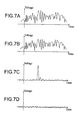
- the DPA includes a step of measuring dissipated power data and a step of analyzing a key based on the difference of dissipated power data.
- input plaintext containing a seiquence of different codes is serially provided to an encryption device such as a smart card and the like, and change of dissipated electric power with time in its encryption processor in response to the input plaintext is measured by using an oscilloscope and the like, to thereby obtain a dissipated power curve.
- FIGURE 7A shows an example of such a dissipated power curve.
- the measuring is performed for different plaintext inputs to collect a statistically sufficient number of dissipated power curves.
- a set G is defined herein as a set of dissipated power curves obtained by the measurement.
- FIGURE 5 shows an example of encryption which is formed by a combination of the key XOR (FIGURE 2) and the nonlinear transform (FIGURE 4) in series connection.
- the DPA for the encryption is described below.
- FIGURE 6 shows elements relevant to an arbitrary nonlinear transform element w i shown in FIGURE 5.
- a value m i indicates a known multi-bit value within arbitrary input plaintext
- k 1 , k 0 ⁇ indicates an element value of an unknown key K
- a function w i indicates an element transform function in a known SBox table
- the element value of the key used in the processor is assumed as an arbitrary value k i '.
- G 0 (k i ') ⁇ G
- an e-th bit value in z i ' w i (m i ⁇ k i ') is 0 ⁇
- G 1 (k i ') ⁇ G
- an e-th bit value in z i ' w i (m i ⁇ k i ') is 1 ⁇ where "e" is a natural number indicating the e-th least significant bit.
- FIGURE 7A shows an example of an average dissipated power curve obtained from the dissipated power curves which belong to the set G 1 .
- the difference dissipated power curve as shown in FIGURE 7D which represents the difference between the curves of FIGURE 7A and FIGURE 7B becomes a generally flat curve. Therefore, the key k i can be estimated from the difference dissipated power curve with the spike which is generated in accordance with the assumed k i '. By generating the difference dissipated power curves for the k i for all i's, the key K can be successfully analyzed or ultimately determined.
- the following equation (4) can be obtained using the Hamming weight HW of z i , where the Hamming weight is defined as the number of bits having a value of one in a binary value which represents a certain numerical value.
- the DPA can be also applied to an encryption device which has a configuration in which the linear transform L of FIGURE 3 is incorporated into the device of FIGURE 4.
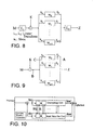
- FIGURE 8 shows an encryption device having a configuration in which two linear transforms are added before and after the encryption device of FIGURE 4.
- L 1 and L 2 are assumed to be permutation functions and w i is assumed to be an SBox of the DES
- the configuration of FIGURE 8 is equivalent to the F function of the DES.
- FIPS 46 "Data encryption standard" Federal Information Processing Standards Publication 46, U.S. Department of Commerce/National Bureau of Standards, National Technical Information Service, Springfield, Virginia, 1977.
- the process in FIGURE 8 can be converted to a process similar to the one as shown in FIGURE 6, and hence the DPA can be applied to estimate a key K, similarly.
- the DPA is applied to the SBox output in the process of nonlinear transform.
- the dissipated power as expressed by the following equation (6) in the adjacent bit model can be represented by a function of bits of a load value, to thereby obtain an effective analysis. This is reported in M. Akkar, R. Bevan, P. Dischamp, and D. Moyart, "Power Analysis, What Is Now Possible" Asiacrypt 2000.
- V(z) a'+a 0 z 0 +a 1 z 1 +...+a 7 z 7 +a 0,1 z 0 z 1 +a 1,2 z 1 z 2 +...+a 6,7 z 6 z 7
- a secret key K is determined by the DPA in three cases or conditions 1-3 as described below.
- FIGURE 9 shows measured points A, B and C for measuring the dissipated power curves in the encryption device of FIGURE 5.
- Conventional countermeasure protection against the DPA includes, for example, a technique of reducing the measurement precision of the dissipatedpower by providing a noise generator in a smart card, and a technique of providing protection in an encryption algorithm.
- the technique of reducing the measurement precision can be easily implemented, but it is not a drastic measure because the analysis can be achieved by increasing the number of times of measurements.
- it may not be easy to provide protection in the encryption algorithm which, however, can be a drastic measure.
- a typical technique of providing protection in the encryption algorithm is described in Thomas S. Messerges, "Securing the AES Finalists against Power Analysis Attacks," in proceedings of Fast Software Encryption Workshop 2000, Springer-Verlag, April 2000, which is called "a masking method".
- FIGURE 10 shows a schematic block diagram of the process in accordance with the random mask value method. This process includes an upper encrypting unit, a lower mask value generating unit, and a random number generator as shown in the figure.
- the encrypting unit computes X i '
- the mask value generating unit computes R i .
- the following equations (7) are established for X i , X i ' , Z i , Z i ', R i , and RO i in the operations shown in FIGURES 2 and 11, FIGURES 3 and 12, and FIGURES 4 and 13A and 13B.
- the XOR operation, Z i X i XOR K i , is performed on the input value X i with the key K i .
- the linear transform, Z i L(X i ), is performed.
- a nonlinear transform is performed using the number, u, of SBoxes expressed by w 1 , w 2 , ... w u-1 .
- a new set of SBoxes expressed by wi' 1 , wi' 2 , ... wi' u-1 are generated and stored in the RAM area by the process using a NewSBox unit, as shown in FIGURE 13A, and a nonlinear transform is performed using these new SBoxes.
- the mask value generating process shown in FIGURE 13A the process is performed using the NewSBox unit, and each of w' 1 , w' 2 , ...
- FIGURE 13B shows a detailed configuration of the NewSBox unit.
- the security of the random mask value method Described briefly below is the security of the random mask value method.
- the Sbox, wi', of FIGURES 13A and 13B in each round shown in FIGURE 10 and in FIGURE 19 as described later changes in accordance with a random number.
- the content of the SBox can not be known by the DPA. That is, since the condition of the case 1 above that the SBox is known is not satisfied, the dissipated power curve measured at the predetermined timing at the measured point A shown in FIGURE 8 can not be divided into G 0 and G 1 in accordance with the equations (1) and (2).
- the encryption device employing the random mask value method is secure against the DPA.
- the random element which changes each time in the measuring is combined at the measured point B at the output of the key XOR function and at the measured point C at the input to an Sbox.
- the condition that the key K is fixed is not satisfied.
- it is secure against the DPA.
- FIGURE 14 shows a general configuration of a conventional N-round Rijndael type process without protection against the DPA.
- Each round of the N-round Rijndael process contains operations of an XOR, a Subbyte (substitute byte), a Shift or shifter and a Mixedcolumn.
- the last round includes another XOR, but does not include a Mixedcolumn.
- K i is called a sub-key.
- FIGURE 15 shows a sub-key generator for generating N+1 128-bit sub-keys, K 0 , K 1 , ... K N , from 128/192/256-bit secret key Ksec in the Rijndael method. The method for generating sub-keys from a secret key is described in the specification of the Rijndael method accessible at http://www.nist.gov/aes/.
- FIGURE 16 shows a configuration of the Subbyte. This process performs a 128-bit-to-128-bit nonlinear transform using S's, each of which represents an 8-bit-to-8-bit transform SBox.
- FIGURE 17 shows a configuration of the Shift. This process rearranges or reshuffles bytes in terms of byte positions.
- FIGURE 18 shows a configuration of the Mixedcolumn. This process performs an operation in a matrix over the field GF (2 8 ).
- FIGURE 19 illustrates the N-round Rijndael method employing the random mask value method as opposed to the conventional N-round Rijndael method illustrated in FIGURE 14.
- the N-round Rijndael method illustrated in FIGURE 19 includes an upper N-round encryption unit, a lower N-round mask value generation unit, and a random number generator, as shown.
- K i represents the sub-key of the i-th round in the Rijndael method.
- RK i represents a random mask value for each sub-key.
- the Subbyte performs a 128-bit-to-128-bit nonlinear transform using sixteen Sboxes, S i,0 , S i,1 , ... S i,15 , in the form as shown in FIGURE 16.
- FIGURE 20 shows a configuration of the NewSBox, which generates sixteen different Sboxes, S i,0 (x), S i,1 (x), ... S i,15 (x), in response to an input value Rin i in accordance with the internally generated random number Rout i , to provide the random number Rout i .
- the Shift and Mixedcolumn are linear transforms shown in FIGURES 17 and 18, similarly to those used in the process of the conventional Rijndael method.
- Steps [1101] to [1109] for the encryption unit and Steps [1201] to [1209] for the mask value generation unit as follows:
- Rin a random mask value generated at Step [1102].
- the Mask is provided to the Shift and Mixedcolumn, and the output from these operations is set to be a new Mask.
- the operated result is set to be a new Mask.
- the encryption employing the random mask value method has drawbacks in that its encrypting speed is a few tenths lower than that of the conventional encryption and it requires a very large RAM area.
- nonlinear transform tables are held in a ROM in the conventional method, while nonlinear transform tables must be generated each time in accordance with a new mask value in the random mask value method, which requires a large amount of computations.
- a large RAM area is required as described above, because, for the conventional nonlinear transform, the new Sboxes are stored in the RAM in each encryption process in the random mask value method, while the nonlinear transform tables are held in the ROM in the conventional method.
- a chip for a low cost smart card such as an ST 16 (manufactured by ST Microelectron) has a RAM area of only about 128 bytes, it is practically impossible to implement the random mask value method.
- the present inventors have recognized that it is advantageous to improve the processing speed and reduce the required RAM area by performing the masking with fixed values rather than the random values.
- the masking method using the fixed values is hereinafter referred to as a fixed mask value method.
- An object of the present invention is to provide efficient protection of an encryption processor for encrypting data with a common key from analysis for decryption.
- Another object of the present invention is to make it difficult to estimate a secret key, and to raise the security of the encryption processor.
- an encryption device includes XOR means and nonlinear transform means.
- the encryption device further includes random number generator means for generating a random number; q fixed values, where q is an integer; and a first selector for selecting one of the q fixed values in response to the random number.
- the XOR means XORs an input thereto with an XOR of a key with the selected fixed value.
- an encryption device includes XOR means and nonlinear transform means.
- the encryption device further includes random number generator means for generating a random number; q sets of masked fixed tables, where q is an integer; and a selector for selecting one of the q sets of fixed tables in response to the random number.
- the nonlinear transform means nonlinearly transforms an input thereto in accordance with the selected set of fixed tables.
- an encryption device includes random number generator means for generating a random number; a plurality of encrypting units coupled in parallel; and a selector for selecting one of the plurality of encrypting units in response to the random number.
- Each of the plurality of encrypting units includes XOR means and nonlinear transform means.
- an encryption device includes random number generator means for generating a random number and a plurality of encrypting rounds.
- Each of the plurality of encrypting rounds includes nonlinear transform means for nonlinearly transforming an input, and XOR means for XORing a first input with a second input.
- the second input of the XOR means is coupled to an output of the nonlinear transform means.
- the nonlinear transform means includes q fixed values, where q is an integer; a selector for selecting one of the q fixed values in response to the random number; and further XOR means for XORing an input with an XOR of a key with said selected fixed value.
- an encryption device includes random number generator means for generating a random number; a plurality of encrypting units coupled in parallel; and a selector for selecting one of the plurality of encrypting units in response to the random number.
- Each of the encrypting units includes a plurality of encrypting rounds.
- Each of the encrypting rounds includes nonlinear transform means for nonlinearly transforming an input; and XOR means for XORing a first input with a second input. The second input to the XOR means is coupled to an output of the nonlinear transform means.
- a program (which may be stored on a storage medium) for use in an encryption device is operable to effect the step of selecting one of a plurality of encryption processes in response to a random number, and the step of encrypting an input value in accordance with the selected encryption process to provide an output.
- the encrypting step includes the step of XORing an input value with an XOR of a key with a fixed value, and the step of nonlinear transforming an input value in accordance with a set of fixed tables.
- an encryption processor for encrypting data using a common key is efficiently protected from analysis for the secret key, estimation of a secret key becomes difficult, and the security of the encryption processor can be enhanced.
- a plurality of fixed values are prepared and switched for selection using a random value in accordance with the fixed mask value method of the invention to thereby obtain effects similar to the conventional random mask value method, while the conventional method masks an input or a key using random values.
- the mask values are limited to specific fixed values.
- the processing speed can be improved by predetermining the mask values.
- the method can be implemented on a platform having a small RAM area, by preparing a set of fixed mask values and by preparing nonlinear transform tables associated with respective fixed mask values in a ROM. For example, since an LSI chip for a low cost smart card such as the ST 16 and the like has a large ROM area of about 6 K bytes, the fixed mask value method is suitable for the low cost smart card.
- FIGURE 21 shows a schematic configuration of a first type of encryption device 100 in accordance with the present invention.
- FIGURES 22 and 23 show configurations of a key XOR and a nonlinear transform, respectively, in the encryption device 100.
- the linear transform in the device may be the one shown in FIGURE 2.
- the encryption device 100 further includes RAM 162 for working memory, ROM 164 for storing fixed mask values, fixed nonlinear transform table SBoxes, linear transform functions L's and the like, and a processor 150 for controlling the processing elements 103 to 107 in accordance with the program stored in a program memory 160 such as a ROM.
- the processor 150 may provide the processing elements 103 to 107 thereon, by executing the program in the memory 160 which is implemented to provide the functions corresponding to the processing elements 103 to 107.
- FIGURE 21 may be considered as a flow diagram.
- the encrypting unit 101 recursively executes the round function defined by a combination of a key XOR of FIGURE 22, the linear transform of FIGURE 2 and a nonlinear transform of FIGURE 23, or executes the round function with a plurality of round function circuits in series connection, each circuit having such a combination.
- the key XOR of FIGURE 22 XORs the key Ki with the fixed mask value FM i,R selected by a switch unit 109 in response to the random number R, to provide a certain value, and XORs the input Xi' with the certain value to provide an output Zi'.
- FIGURE 24 shows a schematic configuration of a second type of encryption device 200 in accordance with the invention.
- FIGURES 25 and 26 show configurations of a key XOR and a nonlinear transform, respectively, in the device 200.
- the linear transform in each one of encrypting units may be the one shown in FIGURE 2.
- the encryption device 200 further includes RAM 262 for working memory, ROM 264 for storing fixed mask values, fixed nonlinear transform table SBoxes, linear transform functions L's and the like, and a processor 250 for controlling the processing elements 203 to 211 in accordance with the program stored in a program memory 260 such as a ROM.
- the processor 250 may provide the processing elements 203 to 211 thereon, by executing the program in the memory 260 which is implemented to provide the functions corresponding to the processing elements 203 to 211.
- FIGURE 24 may be considered as a flow diagram.
- the encrypting units 208 to 209 have identical configurations except that the sets wi i,j of the fixed mask values FM i,j and the respective SBoxes are different from each other.
- Each of the encrypting units 208 to 209 recursively executes the round function defined by a combination of a key XOR of FIGURE 25, the linear transform of FIGURE 2 and a nonlinear transform of FIGURE 26, or executes the round function with a plurality of round function circuits in series connection, each circuit having such a combination.
- the key XOR of FIGURE 25 XORs the key Ki with the fixed mask value FM i,R which is specific to each of the encrypting units 208 to 209, to provide a certain value, and XORs the input Xi' with the certain value to provide an output Zi'.
- the fixed mask value method in accordance with the invention may be suitable for implementation in the low cost smart card. Now, the following problems are taken into consideration in order to provide a more preferable implementation.
- the random mask value method is secure against the DPA, but it may be uncertain to what degree the fixed mask value method is secure.
- the fixed mask value method may possibly be vulnerable to the DPA depending on how it is implemented and on the condition of the fixed mask values.
- the fixed mask value method is advantageous over the random mask value method in that a required RAM area can be smaller by preparing nonlinear transform tables in the ROM.
- the required size of the ROM depends on the number of the prepared fixed mask values.
- the required capacity of the ROM may possibly be considerably large to ensure the security.
- FIGURE 27 shows an example of the first type of encryption device 100 shown in FIGURE 21, which is an encryption device 300 in accordance with the Rijndael method to which the fixed mask value method is applied.
- the processor 150, and the memories 160, 162 and 164 shown in FIGURE 21 are not shown for simplicity.
- a Subbyte 334 for subbyting the output from the XOR 333 in accordance with the selected S i,j,h , a Shift 335 for shifting the output from the Subbyte 334, and a Mixedcolumn 336 for mixedcolumning the output from the Shift 335.
- the (N-1)th encrypting round 311 includes switch units 329 and 339, XORs 331 and 333, a Subbyte 334, and a Shift 335, similarly to the i-th encrypting round 310, but includes no Mixedcolumn.
- FM i,h , FMin h and FMout h are fixed mask values.
- S i,j,h is a fixed SBox.
- the fixed mask values and the SBox values are predetermined.
- serial computation for the masking which is required in the conventional random mask value method is not required in the fixed mask value method.
- the entire process is performed at a higher speed.
- the predetermined fixed mask values and the SBox transform tables are stored in a ROM, for example the ROM 164 shown in FIGURE 21 and the ROM 264 shown in FIGURE 24, rather than a RAM, for example the RAM 162 shown in FIGURE 21 and the RAM 262 shown in FIGURE 24, to thereby drastically reduce the RAM area required for implementation.
- the reduction of the required amount of RAM is advantageous in implementation of the decryption in a low cost smart card with the RAM area of only 128 bytes.
- FIGURE 28 shows a configuration of the Subbyte 334 shown in FIGURE 27.
- the Shift 335 is the one shown in FIGURE 16, and the Mixedcolumn 336 is the one shown in FIGURE 17.
- S i,j,h used in the Subbyte shown in FIGURE 28 is expressed by the following equation (10) using the S which is the SBox for the Subbyte in the conventional Rijndael method shown in FIGURE 16.
- S i,j,h (x) S(x ⁇ a i,j,h ) ⁇ b i,j,h
- a i,j,h and b i,j,h in the equation (10) correspond to Ri i,j and Roi i,j , respectively, in the equation (9), and to the input and output mask values, respectively, for the Subbyte in the i-th round. Since a i,j,h is an input mask value, it is uniquely determined by the preceding mask value, the preceding operations and the like before that Subbyte. On the other hand, b i,j,h can be arbitrary determined.
- Steps [1301] to [1314] The flow of the process of the encryption device 300 shown in FIGURE 27 is described below in Steps [1301] to [1314].
- the steps [1303] to [1309] correspond to the process in the i-th round shown in FIGURE 28.
- Steps [1310] to [1314] correspond to the process in the (N-1) th round shown in FIGURE 27.
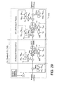
- FIGURE 29 shows an encryption device 400 as another example in accordance with the Rijndael method to which the fixed mask value method is applied.
- the processor 150, the memories 160, 162 and 164 shown in FIGURE 21 are not shown for simplicity.
- the configuration shown in FIGURE 29 is the same as that shown in FIGURE 27, except that sets of SBoxes provided to the respective switch units 339 coupled to the respective Subbytes 334 in the respective round functions are identical. The same elements are not described again.
- FIGURE 30 shows an example of a configuration of the Subbyte 334 shown in FIGURE 29.
- the Subbyte 334 performs the nonlinear transform shown in FIGURE 30 using sixteen Sboxes, S 0,h , S i,h , ... S 15,h , selected by the switch unit 339.
- a process flow of the encryption device 400 of FIGURE 29 corresponds to the process flow for the encryption device 400 of FIGURE 27, where the Subbyte is performed in accordance with a nonlinear transform table S j,h selected by the switch unit 339 from sixteen Sboxes, S 0,h , S 1,h , ... S 15,h , in accordance with the random number h in Steps [1305] and [1311] for every round.
- the tables of the Subbytes 334 are different in the respective rounds, while, in the encryption device 400 of FIGURE 29, identical tables are used in all of the rounds, which is possible for the following reason.
- the input value into the Subbyte (FIGURE 16) in the conventional Rijndael process is expressed as X.
- the input value into the Subbyte shown in FIGURE 30 can be expressed by X XOR C h . This is so because the relation of the equation (11) is effective between the mask values .
- the number of sets of q SBoxes available for each round can be reduced from sixteen sets to only one set by adding a condition for the constant values C h and D h given by the following equations (13) to the equations (12) in which C h and D h are the arbitrary 16-byte constant values.
- the amount of the available ROM required for the SBoxes used in the encryption device 400 of FIGURE 29 can be reduced to one sixth of that in the encryption device 300 of FIGURE 27. Therefore, the ROM area required for the SBoxes in the encryption device 400 of FIGURE 29 which satisfies the equations (13) can be reduced to only 1/ (16N) of that in the encryption device 300 of FIGURE 27.
- the XOR with FMin h and the XOR with FMout h are performed at the input and the output, respectively. However, since it is found that these operations do not contribute to the security, these operations may be eliminated.
- the operation of XORing the key K i with the fixed mask value FM i,h can be eliminated. The elimination of these operations requires a small number of additional operations with the switch units.
- the Rijndael method to which the fixed mask value method is applied can be provided in an amount of computation substantially equivalent to that required for the Rijndael method without protection against the DPA.
- FIGURE 31 shows an example of the second type of encryption device 200 of FIGURE 24, which is a further encryption device 500 in accordance with the Rijndael method to which the fixed mask value method is applied.
- the processor 250, the memories 260, 262 and 264 shown in FIGURE 24 are not shown for simplicity.
- the encryption device 500 includes a random number generator 503 for generating a random number h, switch units 502 and 504 for switching in response to the random number h, and the number, q, of encrypting units 511 to 513, i.e. the 0-th to (q-1)th units coupled in parallel, one of which is selected by the switch units 502 and 504 in response to the random number h.
- Each of the encrypting units 511 to 513 includes a plurality of encrypting rounds 530 (0 ⁇ i ⁇ N-2 for a round i) for receiving an input Xin' and providing an output Xout', and the (N-1) th encrypting round 531 for receiving the output from the preceding round as an input and encrypting the input to generate an output Xout'.
- Each of the 0-th to (N-2)th encrypting rounds 530 which includes a fixed mask value, an XOR 523, a corresponding Subbyte 525, a Shift 526 and a Mixedcolumn 527, performs encryption in accordance with corresponding fixed mask values and fixed SBoxes.
- An XOR 521 is coupled to the input of the 0-th encrypting round 530.
- the (N-1)th encrypting round 531 which includes fixed mask values, XORs 523, 528 and 529, a Subbyte 525 and a Shift 526, performs encryption in accordance with the fixed mask values and fixed SBoxes.
- the XOR value, K i XOR FM j,h predetermined by XORing the key K i with FM j,h is directly provided.
- each key K i may be XORed with FM j,h by an XOR to provide the XOR value to each input of the corresponding XOR or XORs 523 to 528.
- FMin h and FMout h may be eliminated.
- the encryption device 500 of FIGURE 31 also in the encryption device 500 of FIGURE 31, identical SBoxes are used in every round for each unit. If the device 500 is set so as to satisfy the condition of the equations (13), the requirements of the ROM can be reduced, similarly to the encryption device 400 of FIGURE 29.
- the amount of computation performed by the encryption device 500 can be advantageously reduced in that the necessary number of switch units is smaller than that of the encryption device 400, and is substantially equivalent to the amount of computation in the Rijndael method without protection against the DPA. Since the encryption device 500 of FIGURE 31 has more Shifts and Mixedcolumns than the encryption device 400 of FIGURE 29, the size of the circuit of the encryption device 500 becomes larger.
- the encryption device 500 has two selectors or switch units 502 and 504, either one of the left and right switch units 502 and 504 may be used for switching. In this case, the other switch unit may be eliminated.
- the security of the fixed mask value method is described below.
- the operation in the fixed mask value method is substantially the same as that in the random mask value method, and hence the same high security is ensured.
- the security can be proved for a simplified one-round encryption function in the random mask value method.
- the security can be similarly ensured for the encryption devices 400 and 500 shown in FIGURES 29 and 31, respectively, each of which uses the identical SBoxes in every round.
- the security can be raised against the DPA, by setting the condition of the following equation (14) or (15) for c 0,j , c 1,j , ... c q-2,j , and by setting the condition of the following equation (16) for d 0,j , d 1,j , ... d q-2,j .
- the DPA may be performed at the predetermined timing at the measured point A shown in FIGURE 9, and may be performed at the predetermined timing at the measured points B and C.
- the following explains that the encryption devices 400 and 500 of FIGURES 29 and 31, respectively, are sufficiently secure.
- Bit (x, e) described below represents a bit value at the e-th position in x.
- the attacker performs the following processes (i) and (ii) for estimating a key.
- Checking the value of the key can be achieved by checking the relation between the plaintext and the ciphertext in the encryption processor. That is, the encryption of the plaintext by the encryption processor is compared with the encryption of the plaintext using the value of each assumed key to be checked by another encrypting means such as software. If the relations between the plaintext and the ciphertext match with each other between the encryption processor and the other encrypting means, then it is determined that the value of the assumed key is used in the encryption processor. If the two relations do not match with each other, then it is determined that the assumed key is not used.
- LSB least significant bit
- MSBs most significant bits
- SBox is d 0,j , d 1,j , ... d q-1,j .
- WD j (d 0,j ⁇ d 1,j ) ⁇ (d 1,j ⁇ d 2,j ) ⁇ ... ⁇ (d q-2,j ⁇ d q-1,j ),
- the encryption device is most secure against the DPA.
- the required amount of computation for determining the key through the DPA is the maximum value of 2 128 .
- the security against the DPA for the output of the key XOR (at the measured point B shown in FIGURE 9) or the input to the SBox (at the measured point C shown in FIGURE 9).
- the security against the DPA at the predetermined timing at the measured points B and C shown in FIGURE 9 depends on what model can be used to approximate the relation between the measured voltage and the load value when the value is loaded to the RAM in the encryption processor. First, the DPA using an arbitrary model is discussed, and then the DPA using an adjacent bit model expressed by the equation (6) is discussed later.
- WC j (c 0,j ⁇ c 1,j ) ⁇ (c 1,j ⁇ c 2,j ) ⁇ ... ⁇ (c q-2,j ⁇ c q-1,j )
- WC j (wc j,7 wc j,6 wc j,5 wc j,4 wc j,3 wc j,2 wc j,1 wc j,0 ) 2
- the encryption device is most secure against the DPA.
- the required amount of computation for determining the key through the DPA is the maximum value of 2 128 .
- the value j represents the ordinal number of an SBox.
- the value e represents a bit position.
- the amount of computation 2 68 is smaller than the amount of computation 2 128 which is required for computing all of the bit patterns of the key, it is practically impossible to determine the key for decryption within a limited time . Therefore, it is practically impossible to determine a secret key for decryption, even if the DPA is performed on an encryption processor to which the fixed mask value method is applied in accordance with the invention.
- FIGURE 32A shows a configuration of in accordance with the conventional DES.
- FIGURE 32B shows a more detailed configuration of an F function shown in FIGURE 32A.
- the F function includes linear transforms E and P and nonlinear transforms S 1 to S 8 having respective nonlinear transform tables S 1 to S 8 .
- FIGURE 33A shows an example of the first type of encryption device 100 shown in FIGURE 21, which is an encryption device 700 in accordance with the DES encryption of FIGURE 32A and 32B to which the fixed mask value method is applied in a manner similar to the encryption device 400 of FIGURE 29.
- FIGURE 33B shows a more detailed configuration of a F function shown in FIGURE 33A.
- the processor 150, the memories 160, 162 and 164 shown in FIGURE 21 are not shown for simplicity.
- the encryption device 700 includes a random number generator 701 for generating a random number h, a selector 702 for selecting one of the fixed mask values FMin h in response to the random number h to provide the selected value, an XOR 712 for XORing input plaintext with the selected fixed mask value FMin h , a plurality of (sixteen, for example) F function encrypting rounds 710 to 720 for receiving an input and encrypting the input in accordance with the random number h and the sub-key Ki to generate an output, a selector 704 for selecting one of the fixed mask values FMout h in response to the random number h to provide the selected value, and an XOR 714 for XORing the output from the F function encrypting round 720 with the selected fixed mask value FMout h to produce ciphertext.
- a random number generator 701 for generating a random number h
- a selector 702 for selecting one of the fixed mask values FMin h in response to the random number
- Each of the F function encrypting rounds 710 to 720 receives the output from the XOR in the preceding round, performs the F function shown in FIGURE 33B, and XORs, through the XORs (722 and 723), the output from the function and the output from the preceding round to provide an output.
- the F function of FIGURE 33B includes a selector 759 for providing a fixed mask value FM i,h selected in response to the random number h, an XOR 762 for XORing the sub-key K i with the fixed mask value FM i,h to provide an output, an XOR 763 for XORing the output value with an input Xi' linearly transformed by a linear transform E, selectors 752 to 756 for selecting one of Subbytes S i,h in response to the random number h to provide the output from the XOR 763, Subbytes S i,h for performing the Subbyte in accordance with the respective nonlinear table Sboxes S i,h , selectors 754 to 757 for selecting one of the Subbytes S i,h in response to the random number h to provide an output, and a linear transform P for linearly transforming the output from the selectors 754 to 757 to provide an output Zi'.
- the processor 150 in FIGURE 21 controls the processing elements 701 to 763 and the like of the encryption device 700 of FIGURES 33A and 33B in accordance with the program stored in the program memory 160.
- the processor 150 may provide the processing elements 701 to 763 and the like, by executing the program in the memory 160 which is implemented to provide the functions corresponding to the processing elements 701 to 763 and the like.
- FIGURES 33A and 33B may be considered as a flow diagram.
- FIGURE 34A shows an example of the second type of encryption device 200 shown in FIGURE 24, which is an encryption device 800 in accordance with the DES encryption of FIGURES 32A and 32B to which the fixed mask value method is applied in a manner similar to the encryption device 500 of FIGURE 31.
- FIGURE 34B shows a more detailed configuration of a F function shown in FIGURE 34A.
- the processor 250, the memory 260, 262 and 264 shown in FIGURE 24 are not shown for simplicity.
- the encryption device 800 includes a random number generator 801 for generating a random number h, switch units 802 and 804 for performing switching operations in response to the random number h, and a plurality of encrypting units 820 to 830 selected by the switch units 802 and 804 in response to the random number h.
- the processor 250 in FIGURE 24 controls the processing elements 801 to 862 and the like of the encryption device 800 of FIGURES 34A and 34B in accordance with the program stored in the memory 260.
- the processor 150 may provide the processing elements 801 to 862 and the like, by executing the program in the memory 160 which is implemented to provide the functions corresponding to the processing elements 801 to 862 and the like.
- FIGURES 34A and 34B may be considered as a flow diagram.
- Each of the encrypting units 820 to 830 includes a plurality of (sixteen, for example) F function encrypting rounds 840 to 850 for receiving an input and generating an output.
- Each of the F function encrypting rounds 840 to 850 receives the output from the preceding XOR, performs the F function shown in FIGURE 34B in accordance with the Ki XOR FM i,h , XORs, through the XOR (822 and 823), the output from the F function with the output from the preceding round to provide an output.
- FIGURES 33A, 33B, 34A and 34B the input mask FMin may be eliminated similarly to the Rijndael method described above. However, FMout can not be eliminated in the same manner as the Rijndael method.
- FIGURE 35 shows the propagation of the influence of the mask over plural rounds of the Feistel encryption device. In FIGURE 35, a solid line indicates a masked path. The FMout can not be eliminated, because, in the Feistel encryption, the data (A) masked in a certain round affects not only the next round (B) but also the subsequent rounds (C) as shown in FIGURE 35.
- FIGURE 36 shows paths from the generation of a mask to the cancellation of the mask value in the Feistel encryptiondevice.
- the solid lines indicate the masked path.
- the technique of canceling the mask value provides for generating an output mask which is equivalent to the preceding mask to provide cancellation in the XOR in the Feistel encryption, as shown in FIGURE 36, rather than making use of arbitrarily selectable generated mask for a nonlinear transform in the SPN encryption.
- This technique makes it possible to eliminate the last mask FMout in the encryption. If the technique is applied to the encryption of four or more rounds in accordance with the DES and the like, a configuration of canceling a fixed mask value in four rounds may be repeatedly provided, or a fixed mask value to be canceled in the last round may be used.
- the fixed mask value method is applied to all of the rounds.
- an input value must be known and an attacker must control the value.
- the fixed mask value method is applied to only the first several rounds in the encrypting process, then the inputs are unknown and uncontrollable in the subsequent rounds, which hence require no protection against the DPA.
- the required encrypting process for the secure decryption can be reduced.
- TABLE 3 shows comparison between the results of the encryption in implementation of the Rijndael method employing the fixed mask value method, the conventional encryption without protection against the DPA, and the encryption employing the conventional random mask value method.
- S represents the processing time when no protection is provided
- R represents the capacity of the RAM required when no protection is provided
- M represents the capacity of the ROM required when no protection is provided, where R ⁇ M.
- the security is expressed by the number of possible keys to be checked by an attacker to estimate the key.
- the random mask value method requires a long processing time and a large capacity of RAM
- the fixed mask value method requires a capacity of ROM two or three times as large, but does not require a large RAM area.
- the fixed mask value method ensures sufficient security, requiring a processing time comparable to that required by the encryption without the protection.
- the Rijndael method and DES are mainly described, but the fixed mask value method can also be applicable to the SPN encryption method other than the Rijndael method, the Feistel encryption method other than the DES, and any other encryption in combination of these methods, and exhibit similar effectiveness.
- a encryption processor for encrypting data with a common key is efficiently protected from analysis for decryption, estimation of a secret key becomes difficult, and the security of the encryption processor can be enhanced.
Landscapes
- Engineering & Computer Science (AREA)
- Computer Security & Cryptography (AREA)
- Computer Networks & Wireless Communication (AREA)
- Signal Processing (AREA)
- Storage Device Security (AREA)
Abstract
Description

for all j = 0, 1, ... 15,
| Relation between Mask Value and Amount of Computation Required for Determining 128-bit Secret Key by DPA of Loading Sbox Output Values, in Fixed Mask Value Method | |
| Value of WDj=(d0,j⊕d1,j)∨(d1,j⊕d2,j)∨ ...∨(dq-2,j⊕dq-1,j) | Amount of Computation for Key Analysis (q≥2, Arbitrary Model) |
| For all j, 0≤j≤15 WDj=(11111111)2 (Fixed Mask Value Method) | 2128 |
| General Case | 2128-8F, F=f0+f1+...+f15 fj=0 (if WDj=(11111111)2) fj=1 (otherwise) |
| Relation between Mask Value and Amount of Computation Required for Determining 128-bit Secret Key by DPA of Loading Sbox Output Values, for One Common Sbox Set for Subbytes, in Fixed Mask Value Method | ||
| Value of WCj= (c0,j⊕c1,j)∨(c1,j⊕C2,j)∨... V(cq-2,j⊕cq-1,j) | Amount of Computation for Key Analysis (q≥2, Arbitrary Model) | Amount of Computation for Key Analysis (q=2, Adjacent Bit Model) |
| For all j , 0≤j≤15, (111111111)2 (Fixed Mask Value Method) | 2128 | 223 |
| For all j, 0≤j≤15 (01010101)2, (10101010)2 (Fixed Mask Value Method) | 268 | 268 |
| WCj = (wcj,7wcj,6wcj,5wcj,4wcj,3 wcj,2wcj,1wcj,0)2 (General Case) | 2128-(15/16)H H=h0+h1+... +h15 hj= (Number of wcj,e=0) (e=0,1,...7) | 2128-(15/16)H H=h0+h1+... +h15 h= (Number of wcj,e=0) + (Number of wcj,e=wcj+1,e=1) (e=0,1,...7) |
| For all j , 0≤j≤15 (00000000)2 (Minimum Security) | 28 | 28 |
| Comparison between Fixed Mask Value Method, No Protection against DPA, and Random Mask Value Method, in Rijndael Method (R<<M) | ||||
| No Protect | Fixed Mask Value Method | Random Mask Value Method | ||
| q≥2 Arbitrary Model | q=2 Adjacent Bit Model | |||
| Time for Process | S | ≅S | ≅S | >>S (3S to 5S) |
| Amount of RAM | R | ≅R | ≅R | ≥R+M |
| Amount of ROM | M | qM | 2M | ≅M |
| Security | 1 | ≥2128 | 272 | >>2128 |
| Comparison between Fixed Mask Value Method, No Protection against DPA, and Random Mask Value Method, in DES (R«M) | |||
| No Protection | Fixed Mask Value Method | Random Mask Value Method | |
| q=2 | |||
| Time for Process | S | ≅S | >>S (3S to 5S) |
| Amount of RAM | R | ≅R | ≥R+M |
| Amount of ROM | 8M | 16M | ≅8M |
| Security | 1 | >>256 | >>256 |
Claims (28)
- An encryption device comprising XOR means and nonlinear transform means, said encryption device further comprising:random number generator means for generating a random number;q fixed values, where q is an integer; anda first selector for selecting one of said q fixed values in response to the random number;said XOR means XORing an input thereto with an XOR of a key with said selected fixed value.
- The encryption device according to claim 1, further comprising:q sets of masked fixed tables; anda second selector for selecting one of said q sets of fixed tables in response to the random number,said nonlinear transform means nonlinearly transforming an input thereto in accordance with the selected set of fixed tables.
- The encryption device according to claim 1 or 2, further comprising:an encrypting unit comprising said first XOR means and said nonlinear transform means;second XOR means for XORing an input to said encryption device with a fixed value selected in response to the random number; andthird XOR means for XORing an output from said encrypting unit with the fixed value selected in response to the random number.
- An encryption device comprising XOR means and nonlinear transform means, said encryption device further comprising:random number generator means for generating a random number;q sets of masked fixed tables, where q is an integer; anda selector for selecting one of said q sets of fixed tables in response to the random number,said nonlinear transform means nonlinearly transforming an input thereto in accordance with said selected set of fixed tables.
- The encryption device according to claim 4, further comprising a plurality of encrypting rounds, whereineach of said plurality of encrypting rounds comprises the XOR means, the fixed tables and the selector, for that round; andthe fixed tables for said plurality of respective encrypting rounds are identical.
- The encryption device according to claim 4 or 5, wherein
an equation, (c0,j XORc1,j) ∨ (c1,j XOR c2,j) ∨...∨ (cq-2,j XOR cq-2,j) = (11111111)2, is satisfied, where a fixed table before masking is defined as S [x] , and a j-th masked table is defined as Sj[x XOR ci,j] XOR di,j (j = 0, 1, ... 15). - The encryption device according to claim 4 or 5, wherein
the number of sets of tables is q = 2, and an equation, c0,j XOR c1,j = (10101010)2 or (01010101)2, is satisfied, where a fixed table before masking is defined as S[x], and a j-th masked table is defined as Sj[x XOR ci,j] XOR di,j (j = 0, 1, ... 15). - The encryption device according to claim 4 or 5, wherein
an equation, (d0,j XOR d1,j) ∨ (d1,j XOR d2,j) ∨...∨ (dq-2,j XOR dq-2,j) = (11111111)2, is satisfied, where a fixed table before masking is defined as S [x] , and a j-th masked table is defined as Sj[x XOR ci,j] XOR di,j (j = 0, 1, ... 15). - The encryption device according to any of claims 4 - 8, said nonlinear transform means being Subbyte means;
said encryption device further comprising means for shifting an input, and means for mixedcolumning an input - An encryption device comprising:random number generator means for generating a random number;a plurality of encrypting units coupled in parallel; anda selector for selecting one of said plurality of encrypting units in response to the random number;each of said plurality of encrypting units comprises XOR means and nonlinear transform means.
- The encryption device according to claim 10, wherein
said XOR means of said selected encrypting unit XORs an input thereto with an XOR of a key with a fixed value. - The encryption device according to claim 10 or 11, wherein
each of said nonlinear transform means nonlinearly transforms an input thereto in accordance with a corresponding fixed table. - The encryption device according to any of claims 10 - 12, wherein
each of said plurality of encrypting units comprises:second XOR means for XORing an input thereto into that encrypting unit with a fixed value; andthird XOR means for producing an XOR of an input with a fixed value as an output from that encrypting unit. - The encryption device according to any of claims 10, 11 or 13 wherein
said nonlinear transform means of said selected encrypting unit nonlinearly transforms an input thereto in accordance with a fixed table. - The encryption device according to any of claims 10 - 14, whereineach of said plurality of encrypting units comprises a plurality of encrypting rounds;each of said plurality of encrypting rounds comprises XOR means for XORing an input thereto with an XOR of a key with a fixed value, and nonlinear transform means for nonlinearly transforming an input thereto in accordance with a fixed table.
- An encryption device comprising random number generator means for generating a random number and a first plurality of encrypting rounds, whereineach of said plurality of encrypting rounds comprises nonlinear transform means for nonlinearly transforming an input thereto, and XOR means for XORing a first input thereto with a second input thereto;the second input to said XOR means is coupled to an output of said nonlinear transform means; andsaid nonlinear transform means comprises:q fixed values, where q is an integer;a selector for selecting one of said q fixed values in response to the random number; andfurther XOR means for XORing an input thereto with an XOR of a key with said selected fixed value.
- The encryption device according to claim 16, wherein
said nonlinear transform means further comprises therein a plurality of nonlinear transform means for nonlinearly transforming an input in accordance with a fixed table; and a selector for selecting one of said plurality of nonlinear transform means. - The encryption device according to claim 17, wherein
the fixed tables of said respective nonlinear transform means in said respective encrypting rounds are identical. - The encryption device according to any of claims 16 - 18, wherein
a mask is canceled over subsequent ones of said plurality of encrypting rounds. - The encryption device according to any of claims 16 - 19, wherein
masking is performed in each of a second plurality of encrypting rounds of said first plurality of encrypting rounds, said second plurality being smaller than said first plurality. - An encryption device comprising a random number generator means for generating a random number, and a plurality of encrypting rounds, whereineach of said plurality of encrypting rounds comprises nonlinear transform means for nonlinearly transforming an input thereto; and XOR means for XORing a first input thereto and a second input thereto;the second input to said XOR means is connected to an output of said nonlinear transform means; andsaid nonlinear transform means comprises therein nonlinear transform means for nonlinearly transforming an input thereto in accordance with a fixed table and in accordance with the random number.
- An encryption device, comprising:random number generator means for generating a random number;a plurality of encrypting units coupled in parallel; anda selector for selecting one of said plurality of encrypting units in response to the random number, wherein,each of said encrypting units comprises a plurality of encrypting rounds;each of said encrypting rounds comprises:nonlinear transform means for nonlinearly transforming an input thereto; andXOR means for XORing a first input thereto with a second input thereto; andthe second input to said XOR means is coupled to an output of said nonlinear transform means.
- The encryption device according to claim 22, wherein said nonlinear transform means comprises:further XOR means for XORing an input thereto with an XOR of a key with a fixed value; andfurther nonlinear transform means for nonlinearly transforming an input thereto in accordance with a fixed table.
- The encryption device according to any of claims 22 or 23, wherein
an equation, (d0,j XOR d1,j) ∨ (d1,j XOR d2,j) ∨...∨ (dq-2,j XOR dq-2,j) = (1111)2, is satisfied, where a fixed table before masking is defined as Sj[x], and a j-th masked table is defined as Sj' [x XOR ci,j] XOR di,j (j = 0, 1, ... 7). - A program stored on a storage medium for use in an encryption device, said program operable to effect the steps of:selecting one of q fixed values, where q is an integer, in response to a random number;XORing an input value with an XOR of a key with said selected fixed value;selecting one set of q sets of masked fixed tables in response to the random number; andnonlinearly transforming an input value in accordance with said selected set of fixed tables.
- A program stored on a storage medium for use in an encryption device, said program operable to effect the steps of:selecting one of a plurality of encryption processes in response to a random number, andencrypting an input value in accordance with said selected encryption process to provide an output;the encrypting step comprising the steps of:XORing an input value with an XOR of a key with a fixed value, andnonlinear transforming an input value in accordance with a set of fixed tables.
- A program stored on a storage medium for use in an encryption device, said program operable to effect the steps of:nonlinear transforming an input value to provide an output, andXORing a first input value with said output as a second input value;the nonlinear transforming step comprising the steps of:selecting one of q fixed values in response to a random number, where q is an integer,XORing an input value with an XOR of a key with said selected fixed value, andnonlinear transforming an input value in accordance with a set of fixed tables associated with the random number.
- A program stored on a. storage medium for use in an encryption device, said program operable to effect the steps of:selecting one of a plurality of encryption processes in response to a random number, andencrypting an input value in accordance with said selected encryption processes to provide an output;the encrypting step comprising the steps of:nonlinear transforming an input value to produce an output, andXORing a first input value with said output as a second input value.
Priority Applications (1)
| Application Number | Priority Date | Filing Date | Title |
|---|---|---|---|
| EP07000759A EP1772985A1 (en) | 2001-06-13 | 2002-01-25 | Encryption secured against Differential Power Analysis (DPA) |
Applications Claiming Priority (2)
| Application Number | Priority Date | Filing Date | Title |
|---|---|---|---|
| JP2001178407 | 2001-06-13 | ||
| JP2001178407A JP4596686B2 (en) | 2001-06-13 | 2001-06-13 | Secure encryption against DPA |
Related Child Applications (1)
| Application Number | Title | Priority Date | Filing Date |
|---|---|---|---|
| EP07000759A Division EP1772985A1 (en) | 2001-06-13 | 2002-01-25 | Encryption secured against Differential Power Analysis (DPA) |
Publications (4)
| Publication Number | Publication Date |
|---|---|
| EP1267514A2 true EP1267514A2 (en) | 2002-12-18 |
| EP1267514A9 EP1267514A9 (en) | 2003-05-21 |
| EP1267514A3 EP1267514A3 (en) | 2003-11-05 |
| EP1267514B1 EP1267514B1 (en) | 2007-08-29 |
Family
ID=19019110
Family Applications (2)
| Application Number | Title | Priority Date | Filing Date |
|---|---|---|---|
| EP07000759A Withdrawn EP1772985A1 (en) | 2001-06-13 | 2002-01-25 | Encryption secured against Differential Power Analysis (DPA) |
| EP02001146A Expired - Lifetime EP1267514B1 (en) | 2001-06-13 | 2002-01-25 | Encryption secured against Differential Power Analysis (DPA) |
Family Applications Before (1)
| Application Number | Title | Priority Date | Filing Date |
|---|---|---|---|
| EP07000759A Withdrawn EP1772985A1 (en) | 2001-06-13 | 2002-01-25 | Encryption secured against Differential Power Analysis (DPA) |
Country Status (4)
| Country | Link |
|---|---|
| US (1) | US7386130B2 (en) |
| EP (2) | EP1772985A1 (en) |
| JP (1) | JP4596686B2 (en) |
| DE (1) | DE60222052T2 (en) |
Cited By (25)
| Publication number | Priority date | Publication date | Assignee | Title |
|---|---|---|---|---|
| DE10341096A1 (en) * | 2003-09-05 | 2005-03-31 | Giesecke & Devrient Gmbh | Transition between masked representations of a value in cryptographic calculations |
| EP1601132A1 (en) * | 2004-05-24 | 2005-11-30 | Research In Motion Limited | Table Masking for Resistance to Power Analysis Attacks |
| WO2007000702A2 (en) | 2005-06-29 | 2007-01-04 | Koninklijke Philips Electronics N.V. | Arrangement for and method of protecting a data processing device against a cryptographic attack or analysis |
| EP1833190A1 (en) * | 2006-03-07 | 2007-09-12 | Research In Motion Limited | Table splitting for cryptographic processes |
| GB2422693B (en) * | 2005-01-27 | 2008-04-02 | Samsung Electronics Co Ltd | Cryptographic logic circuits and method of performing logic operations |
| GB2443358A (en) * | 2005-01-27 | 2008-04-30 | Samsung Electronics Co Ltd | Cryptographic logic circuits and method of performing logic operations |
| DE102005012098B4 (en) * | 2004-03-16 | 2010-04-08 | Samsung Electronics Co., Ltd., Suwon | Data cipher processor as well as AES cipher system and AES ciphers |
| US7724897B2 (en) | 2005-04-28 | 2010-05-25 | Panasonic Corporation | Program converter, encrypting device, and encrypting method |
| CN101147182B (en) * | 2005-03-31 | 2010-09-01 | 松下电器产业株式会社 | Data encryption device and data encryption method |
| US7848514B2 (en) | 2004-05-24 | 2010-12-07 | Research In Motion Limited | Table masking for resistance to power analysis attacks |
| EP2195761A4 (en) * | 2007-10-01 | 2012-01-18 | Research In Motion Ltd | SUBSTITUTE TABLE MASKING FOR ENCRYPTION PROCESS |
| US8325928B2 (en) | 2004-04-16 | 2012-12-04 | Research In Motion Limited | Security countermeasure for power analysis attacks |
| WO2013028056A1 (en) * | 2011-08-19 | 2013-02-28 | Mimos Berhad | Method and system for providing a secured internet protocol based communication |
| US8619985B2 (en) | 2010-04-27 | 2013-12-31 | Research In Motion Limited | Table splitting for cryptographic processes |
| EP1924023A3 (en) * | 2006-11-16 | 2014-12-17 | Fujitsu Limited | Encrypting apparatus for symmetric key cipher |
| EP2947841A4 (en) * | 2014-04-16 | 2016-03-02 | Shenzhen State Micro Tech Co | Encryption device and method of defending against differential power analysis attack |
| CN106161005A (en) * | 2015-03-31 | 2016-11-23 | 北京南瑞智芯微电子科技有限公司 | The mask method of a kind of block encryption algorithm attack protection and device |
| EP3208788A1 (en) * | 2016-02-22 | 2017-08-23 | Eshard | Method of protecting a circuit against a side-channel analysis |
| FR3048096A1 (en) * | 2016-02-22 | 2017-08-25 | Eshard | METHOD FOR PROTECTING A CIRCUIT AGAINST AUXILIARY CHANNEL ANALYSIS |
| EP3264397A1 (en) * | 2016-06-28 | 2018-01-03 | Eshard | A protection method and device against a side-channel analysis |
| EP3264396A1 (en) * | 2016-06-28 | 2018-01-03 | Eshard | A method for protecting a substitution operation using a substitution table against a side-channel analysis |
| CN107547190A (en) * | 2016-06-28 | 2018-01-05 | 埃沙尔公司 | For protecting method of the replacement operation for using substitution table from side Multiple Channel Analysis |
| WO2018100246A1 (en) * | 2016-11-30 | 2018-06-07 | Widlund Sam | Method and arrangement for encrypting data |
| CN109644125A (en) * | 2016-09-30 | 2019-04-16 | 英特尔公司 | The linear mask circuit immune for the side channel of Advanced Encryption Standard hardware |
| US11070359B2 (en) | 2016-06-28 | 2021-07-20 | Eshard | Protection method and device against a side-channel analysis |
Families Citing this family (81)
| Publication number | Priority date | Publication date | Assignee | Title |
|---|---|---|---|---|
| US7092523B2 (en) | 1999-01-11 | 2006-08-15 | Certicom Corp. | Method and apparatus for minimizing differential power attacks on processors |
| US7599491B2 (en) * | 1999-01-11 | 2009-10-06 | Certicom Corp. | Method for strengthening the implementation of ECDSA against power analysis |
| FR2818772A1 (en) * | 2000-12-21 | 2002-06-28 | Bull Cp8 | METHOD OF SECURING A LOGIC OR MATHEMATICAL OPERATOR IMPLANTED IN A MICROPROCESSOR ELECTRONIC MODULE, AND THE ASSOCIATED ELECTRONIC MODULE AND THE ON-LINE SYSTEM |
| AU2003207931A1 (en) * | 2002-03-07 | 2003-09-16 | Axalto Sa | Method for making safe an electronic cryptography assembly with a secret key |
| JP4515716B2 (en) * | 2002-04-03 | 2010-08-04 | パナソニック株式会社 | Extended key generation device, encryption device, and encryption system |
| JP4357815B2 (en) | 2002-09-11 | 2009-11-04 | 株式会社東芝 | Cryptographic operation circuit |
| FR2844896A1 (en) * | 2002-09-19 | 2004-03-26 | St Microelectronics Sa | Power supply method for an asynchronous calculation or processing element, e.g. for use in authorization circuits, to prevent attacks based on power analysis, whereby the power supply to the calculation element is randomly varied |
| US7190791B2 (en) * | 2002-11-20 | 2007-03-13 | Stephen Laurence Boren | Method of encryption using multi-key process to create a variable-length key |
| JP2004212828A (en) * | 2003-01-08 | 2004-07-29 | Sony Corp | Cryptographic processing device, cryptographic processing method, and computer program |
| EP1457858A1 (en) * | 2003-03-14 | 2004-09-15 | SCHLUMBERGER Systèmes | Method for securing an electronic system comprising a cryptoprocessor |
| JP3927151B2 (en) * | 2003-05-30 | 2007-06-06 | 株式会社東芝 | Storage device |
| JP3998616B2 (en) * | 2003-09-10 | 2007-10-31 | 株式会社東芝 | Encryption / decryption module |
| WO2005027403A1 (en) * | 2003-09-11 | 2005-03-24 | Renesas Technology Corp. | Information processing device |
| JP4611643B2 (en) * | 2004-01-16 | 2011-01-12 | 三菱電機株式会社 | Individual key generator |
| KR101061906B1 (en) | 2004-02-19 | 2011-09-02 | 삼성전자주식회사 | Basic Computing Device and Method Safe for Power Analysis Attack |
| EP1733502B1 (en) * | 2004-03-29 | 2009-09-30 | Stmicroelectronics Sa | Processor for executing an aes-type algorithm |
| EP1596278A1 (en) * | 2004-05-11 | 2005-11-16 | Axalto SA | Method to protect a cryptographic unit through homographic masking |
| JP4589327B2 (en) * | 2004-07-07 | 2010-12-01 | 三菱電機株式会社 | Electronic device and data processing method |
| KR20060081847A (en) * | 2005-01-10 | 2006-07-13 | 삼성전자주식회사 | Smart card and its way to protect the secret key |
| US8467535B2 (en) * | 2005-01-18 | 2013-06-18 | Certicom Corp. | Accelerated verification of digital signatures and public keys |
| US8204232B2 (en) | 2005-01-18 | 2012-06-19 | Certicom Corp. | Accelerated verification of digital signatures and public keys |
| EP1860630B1 (en) | 2005-03-16 | 2018-12-26 | Mitsubishi Electric Corporation | Data converting apparatus and data converting method |
| EP1876753B1 (en) * | 2005-04-27 | 2016-03-02 | Panasonic Intellectual Property Management Co., Ltd. | Confidential information processing host device and confidential information processing method |
| JP4887668B2 (en) * | 2005-06-09 | 2012-02-29 | ソニー株式会社 | Encryption / decryption processing circuit and encryption / decryption system |
| JP4586163B2 (en) * | 2005-09-09 | 2010-11-24 | 国立大学法人岩手大学 | Encryption system |
| JP4783104B2 (en) | 2005-09-29 | 2011-09-28 | 株式会社東芝 | Encryption / decryption device |
| FR2893796B1 (en) * | 2005-11-21 | 2008-01-04 | Atmel Corp | ENCRYPTION PROTECTION METHOD |
| JP2007189659A (en) * | 2005-12-15 | 2007-07-26 | Toshiba Corp | ENCRYPTION DEVICE, ENCRYPTION METHOD, AND ENCRYPTION PROGRAM |
| DE602006020010D1 (en) * | 2005-12-19 | 2011-03-24 | St Microelectronics Sa | Protection of the execution of a DES algorithm |
| JP2007192893A (en) * | 2006-01-17 | 2007-08-02 | Sony Corp | Cryptographic processing apparatus, cryptographic processing method, and computer program |
| JP4986206B2 (en) * | 2006-02-22 | 2012-07-25 | 株式会社日立製作所 | Cryptographic processing method and cryptographic processing apparatus |
| US8379841B2 (en) | 2006-03-23 | 2013-02-19 | Exegy Incorporated | Method and system for high throughput blockwise independent encryption/decryption |
| EP1840732A1 (en) * | 2006-03-31 | 2007-10-03 | Axalto SA | Protection against side channel attacks |
| FR2903508B1 (en) * | 2006-07-10 | 2008-10-17 | Sagem Defense Securite | PROTECTION OF A PROGRAM INTERPRETED BY A VIRTUAL MACHINE |
| JP4882598B2 (en) * | 2006-07-28 | 2012-02-22 | ソニー株式会社 | Cryptographic processing apparatus, cryptographic processing algorithm construction method, cryptographic processing method, and computer program |
| JP5023624B2 (en) * | 2006-09-01 | 2012-09-12 | ソニー株式会社 | Cryptographic processing apparatus, cryptographic processing method, and computer program |
| US9411976B2 (en) * | 2006-12-01 | 2016-08-09 | Maidsafe Foundation | Communication system and method |
| US8422668B1 (en) * | 2006-12-15 | 2013-04-16 | Spansion Llc | Table lookup operation on masked data |
| US7949130B2 (en) | 2006-12-28 | 2011-05-24 | Intel Corporation | Architecture and instruction set for implementing advanced encryption standard (AES) |
| US7970129B2 (en) * | 2007-04-19 | 2011-06-28 | Spansion Llc | Selection of a lookup table with data masked with a combination of an additive and multiplicative mask |
| JP4936996B2 (en) | 2007-05-24 | 2012-05-23 | 株式会社東芝 | Nonlinear data converter, encryption device, and decryption device |
| EP2186250B1 (en) | 2007-08-31 | 2019-03-27 | IP Reservoir, LLC | Method and apparatus for hardware-accelerated encryption/decryption |
| US7945050B2 (en) * | 2007-09-28 | 2011-05-17 | Intel Corporation | Suppressing power supply noise using data scrambling in double data rate memory systems |
| US8503678B2 (en) * | 2007-09-28 | 2013-08-06 | Intel Corporation | Suppressing power supply noise using data scrambling in double data rate memory systems |
| KR101011264B1 (en) * | 2008-01-18 | 2011-01-27 | 고려대학교 산학협력단 | Aria masking method and aria encryption device and method using same |
| EP2273472B1 (en) | 2008-03-31 | 2016-02-17 | Fujitsu Limited | Coder equipped with common key code function and built-in equipment |
| JP5268609B2 (en) * | 2008-12-09 | 2013-08-21 | 株式会社東芝 | Cryptographic processing apparatus and calculation method |
| JP5202350B2 (en) * | 2009-01-16 | 2013-06-05 | 三菱電機株式会社 | Cryptographic processing apparatus, cryptographic processing method, and cryptographic processing program |
| FR2941343B1 (en) * | 2009-01-20 | 2011-04-08 | Groupe Des Ecoles De Telecommunications Get Ecole Nat Superieure Des Telecommunications Enst | CIRCUIT OF CRYPTOGRAPHY, PROTECTS IN PARTICULAR AGAINST ATTACKS BY OBSERVATION OF LEAKS OF INFORMATION BY THEIR ENCRYPTION. |
| JP4837058B2 (en) * | 2009-03-10 | 2011-12-14 | 株式会社東芝 | Arithmetic apparatus and program |
| US9654280B2 (en) | 2009-03-10 | 2017-05-16 | Irdeto B.V. | White-box cryptographic system with input dependent encodings |
| JP2010245881A (en) * | 2009-04-07 | 2010-10-28 | Toshiba Corp | Cryptographic processing device |
| US8615078B2 (en) * | 2009-08-21 | 2013-12-24 | Electronics And Telecommunications Research Institute | Method and apparatus for processing F-function in seed encryption system |
| JP2011169977A (en) * | 2010-02-16 | 2011-09-01 | Renesas Electronics Corp | Cryptography processing device |
| DE102010028375A1 (en) * | 2010-04-29 | 2011-11-03 | Robert Bosch Gmbh | Method for protecting functional cryptographic operations against side channel attacks for cryptography system in car, involves performing non-functional cryptographic operations supplementary to functional cryptographic operations |
| DE102010029735A1 (en) * | 2010-06-07 | 2011-12-08 | Robert Bosch Gmbh | Method for generating a bit vector |
| JP5060606B2 (en) * | 2010-09-17 | 2012-10-31 | 株式会社東芝 | Encryption device |
| US20120079462A1 (en) * | 2010-09-24 | 2012-03-29 | SoftKrypt LLC | Systems and methods of source software code obfuscation |
| KR20120070873A (en) * | 2010-12-22 | 2012-07-02 | 한국전자통신연구원 | Subchannel prevention masked addition operator |
| FR2977953A1 (en) * | 2011-07-13 | 2013-01-18 | St Microelectronics Rousset | PROTECTION OF A MODULAR EXPONENTIATION CALCULATION BY ADDING A RANDOM QUANTITY |
| US8525545B1 (en) | 2011-08-26 | 2013-09-03 | Lockheed Martin Corporation | Power isolation during sensitive operations |
| US8624624B1 (en) | 2011-08-26 | 2014-01-07 | Lockheed Martin Corporation | Power isolation during sensitive operations |
| JP5481455B2 (en) * | 2011-09-27 | 2014-04-23 | 株式会社東芝 | Cryptographic processing device |
| US8745376B2 (en) | 2011-10-14 | 2014-06-03 | Certicom Corp. | Verifying implicit certificates and digital signatures |
| JP5711681B2 (en) * | 2012-03-06 | 2015-05-07 | 株式会社東芝 | Cryptographic processing device |
| FR2995111B1 (en) * | 2012-09-04 | 2015-07-24 | Morpho | PROTECTION AGAINST AUXILIARY CHANNELS |
| CN103001762B (en) * | 2012-11-25 | 2015-08-19 | 宁波大学 | A kind of cipherware is defendd the method for null value power consumption attack |
| DE102012025416A1 (en) * | 2012-12-21 | 2014-06-26 | Giesecke & Devrient Gmbh | Method for operating a portable data carrier and such a portable data carrier |
| JP5500277B2 (en) * | 2013-01-28 | 2014-05-21 | 富士通株式会社 | Encryption device and built-in device equipped with a common key encryption function |
| US9959429B2 (en) * | 2013-03-15 | 2018-05-01 | Cryptography Research, Inc. | Asymmetrically masked multiplication |
| US10015152B2 (en) * | 2014-04-02 | 2018-07-03 | International Business Machines Corporation | Securing data in a dispersed storage network |
| US9871651B2 (en) | 2014-06-16 | 2018-01-16 | Cisco Technology, Inc. | Differential power analysis countermeasures |
| US9654111B1 (en) * | 2014-11-12 | 2017-05-16 | Maxim Integrated Products, Inc. | Systems and methods for protecting data using reconfigurable logic paths |
| US9792246B2 (en) | 2014-12-27 | 2017-10-17 | Intel Corporation | Lower-power scrambling with improved signal integrity |
| DE102015115649A1 (en) | 2015-09-16 | 2017-03-16 | Claas Tractor Sas | Agricultural work vehicle |
| US10243937B2 (en) * | 2016-07-08 | 2019-03-26 | Nxp B.V. | Equality check implemented with secret sharing |
| US11507699B2 (en) * | 2019-09-27 | 2022-11-22 | Intel Corporation | Processor with private pipeline |
| KR102932484B1 (en) | 2020-02-26 | 2026-02-26 | 삼성전자주식회사 | A security circuit including dual encoder and endecryptor including thereof |
| JP7314108B2 (en) * | 2020-08-27 | 2023-07-25 | 株式会社東芝 | Cryptographic processing device, cryptographic processing method and program |
| US12244686B2 (en) | 2021-11-23 | 2025-03-04 | Samsung Electronics Co., Ltd. | Image sensor, image processing system having the same and operating method of the same |
| TWI778902B (en) * | 2021-12-30 | 2022-09-21 | 新唐科技股份有限公司 | Addition mask generator, encryptor and method for generating stream key |
Family Cites Families (21)
| Publication number | Priority date | Publication date | Assignee | Title |
|---|---|---|---|---|
| US5452358A (en) | 1994-02-08 | 1995-09-19 | Apple Computer, Inc. | Method and apparatus for improving the security of an electronic codebook encryption scheme utilizing a data dependent encryption function |
| GB2288519A (en) * | 1994-04-05 | 1995-10-18 | Ibm | Data encryption |
| US5870470A (en) | 1996-02-20 | 1999-02-09 | International Business Machines Corporation | Method and apparatus for encrypting long blocks using a short-block encryption procedure |
| EP1088295B1 (en) * | 1998-06-03 | 2007-08-15 | Cryptography Research Inc. | Balanced cryptographic computational method and apparatus for leak minimization in smartcards and other cryptosystems |
| IL139935A (en) * | 1998-06-03 | 2005-06-19 | Cryptography Res Inc | Des and other cryptographic processes with leak minimization for smartcards and other cryptosystems |
| JP3600454B2 (en) * | 1998-08-20 | 2004-12-15 | 株式会社東芝 | Encryption / decryption device, encryption / decryption method, and program storage medium therefor |
| US6275586B1 (en) * | 1998-09-10 | 2001-08-14 | Igt | Cryptographically secure pseudo random number generator |
| FR2784831B1 (en) | 1998-10-16 | 2000-12-15 | Gemplus Card Int | COUNTER-MEASUREMENT METHOD IN AN ELECTRONIC COMPONENT USING A SECRET KEY CRYPTOGRAPHY ALGORITHM |
| FR2784829B1 (en) | 1998-10-16 | 2000-12-29 | Gemplus Card Int | COUNTER-MEASUREMENT METHOD IN AN ELECTRONIC COMPONENT USING A SECRET KEY CRYPTOGRAPHY ALGORITHM |
| FR2785477B1 (en) | 1998-10-29 | 2000-12-29 | Gemplus Card Int | COUNTER-MEASUREMENT METHOD IN AN ELECTRONIC COMPONENT USING A SECRET KEY CRYPTOGRAPHY ALGORITHM |
| JP2000165375A (en) * | 1998-11-30 | 2000-06-16 | Hitachi Ltd | Information processing device, IC card |
| FR2789535B1 (en) | 1999-02-04 | 2001-09-28 | Bull Cp8 | METHOD FOR SECURING AN ELECTRONIC ASSEMBLY OF SECRET KEY CRYPTOGRAPHY AGAINST ATTACKS BY PHYSICAL ANALYSIS |
| FR2789776B1 (en) | 1999-02-17 | 2001-04-06 | Gemplus Card Int | COUNTER-MEASUREMENT METHOD IN AN ELECTRONIC COMPONENT USING A SECRET KEY CRYPTOGRAPHY ALGORITHM |
| FR2790890B1 (en) * | 1999-03-08 | 2001-04-27 | Gemplus Card Int | COUNTER-MEASUREMENT METHOD IN AN ELECTRONIC COMPONENT USING A SECRET KEY CRYPTOGRAPHY ALGORITHM |
| JP2000305453A (en) | 1999-04-21 | 2000-11-02 | Nec Corp | Ciphering device, deciphering device, and ciphering and deciphering device |
| US6295606B1 (en) * | 1999-07-26 | 2001-09-25 | Motorola, Inc. | Method and apparatus for preventing information leakage attacks on a microelectronic assembly |
| DE19936529C1 (en) | 1999-08-03 | 2001-02-01 | Orga Kartensysteme Gmbh | Method for encrypting data using standard encryption in a microprocessor-based, portable data carrier |
| WO2001024439A1 (en) * | 1999-09-29 | 2001-04-05 | Hitachi, Ltd. | Device, program or system for processing secret information |
| CA2298990A1 (en) * | 2000-02-18 | 2001-08-18 | Cloakware Corporation | Method and system for resistance to power analysis |
| FR2809893B1 (en) * | 2000-06-02 | 2002-11-15 | Gemplus Card Int | COUNTER-MEASUREMENT METHOD IN AN ELECTRONIC COMPONENT USING A PUBLIC KEY CRYPTOGRAPHY ALGORITHM ON AN ELLIPTICAL CURVE |
| US7000111B1 (en) * | 2000-11-07 | 2006-02-14 | Ericsson Inc. | Method for masking secret multiplicands |
-
2001
- 2001-06-13 JP JP2001178407A patent/JP4596686B2/en not_active Expired - Fee Related
- 2001-12-28 US US10/028,265 patent/US7386130B2/en not_active Expired - Fee Related
-
2002
- 2002-01-25 EP EP07000759A patent/EP1772985A1/en not_active Withdrawn
- 2002-01-25 EP EP02001146A patent/EP1267514B1/en not_active Expired - Lifetime
- 2002-01-25 DE DE60222052T patent/DE60222052T2/en not_active Expired - Lifetime
Cited By (44)
| Publication number | Priority date | Publication date | Assignee | Title |
|---|---|---|---|---|
| US8290145B2 (en) | 2003-09-05 | 2012-10-16 | Giesecke & Devrient Gmbh | Transition between masked representations of a value during cryptographic calculations |
| DE10341096A1 (en) * | 2003-09-05 | 2005-03-31 | Giesecke & Devrient Gmbh | Transition between masked representations of a value in cryptographic calculations |
| DE102005012098B4 (en) * | 2004-03-16 | 2010-04-08 | Samsung Electronics Co., Ltd., Suwon | Data cipher processor as well as AES cipher system and AES ciphers |
| US7965836B2 (en) | 2004-03-16 | 2011-06-21 | Samsung Electronics Co., Ltd. | Data cipher processors |
| US8325928B2 (en) | 2004-04-16 | 2012-12-04 | Research In Motion Limited | Security countermeasure for power analysis attacks |
| US8638944B2 (en) | 2004-04-16 | 2014-01-28 | Blackberry Limited | Security countermeasures for power analysis attacks |
| US7848514B2 (en) | 2004-05-24 | 2010-12-07 | Research In Motion Limited | Table masking for resistance to power analysis attacks |
| EP1601132A1 (en) * | 2004-05-24 | 2005-11-30 | Research In Motion Limited | Table Masking for Resistance to Power Analysis Attacks |
| US8184806B2 (en) | 2004-05-24 | 2012-05-22 | Research In Motion Limited | Table masking for resistance to power analysis attacks |
| GB2422693B (en) * | 2005-01-27 | 2008-04-02 | Samsung Electronics Co Ltd | Cryptographic logic circuits and method of performing logic operations |
| GB2443358A (en) * | 2005-01-27 | 2008-04-30 | Samsung Electronics Co Ltd | Cryptographic logic circuits and method of performing logic operations |
| CN101147182B (en) * | 2005-03-31 | 2010-09-01 | 松下电器产业株式会社 | Data encryption device and data encryption method |
| US8094811B2 (en) | 2005-03-31 | 2012-01-10 | Panasonic Corporation | Data encryption device and data encryption method |
| US7724897B2 (en) | 2005-04-28 | 2010-05-25 | Panasonic Corporation | Program converter, encrypting device, and encrypting method |
| US8184805B2 (en) | 2005-04-28 | 2012-05-22 | Panasonic Corporation | Program converter, encrypting device, and encrypting method |
| WO2007000702A2 (en) | 2005-06-29 | 2007-01-04 | Koninklijke Philips Electronics N.V. | Arrangement for and method of protecting a data processing device against a cryptographic attack or analysis |
| US8738927B2 (en) | 2005-06-29 | 2014-05-27 | Irdeto B.V. | Arrangement for and method of protecting a data processing device against an attack or analysis |
| EP1833190A1 (en) * | 2006-03-07 | 2007-09-12 | Research In Motion Limited | Table splitting for cryptographic processes |
| EP1924023A3 (en) * | 2006-11-16 | 2014-12-17 | Fujitsu Limited | Encrypting apparatus for symmetric key cipher |
| US8553877B2 (en) | 2007-10-01 | 2013-10-08 | Blackberry Limited | Substitution table masking for cryptographic processes |
| EP2195761A4 (en) * | 2007-10-01 | 2012-01-18 | Research In Motion Ltd | SUBSTITUTE TABLE MASKING FOR ENCRYPTION PROCESS |
| US8619985B2 (en) | 2010-04-27 | 2013-12-31 | Research In Motion Limited | Table splitting for cryptographic processes |
| WO2013028056A1 (en) * | 2011-08-19 | 2013-02-28 | Mimos Berhad | Method and system for providing a secured internet protocol based communication |
| EP2947841A4 (en) * | 2014-04-16 | 2016-03-02 | Shenzhen State Micro Tech Co | Encryption device and method of defending against differential power analysis attack |
| CN106161005A (en) * | 2015-03-31 | 2016-11-23 | 北京南瑞智芯微电子科技有限公司 | The mask method of a kind of block encryption algorithm attack protection and device |
| US10230521B2 (en) | 2016-02-22 | 2019-03-12 | Eshard | Method of testing the resistance of a circuit to a side channel analysis |
| US10243729B2 (en) | 2016-02-22 | 2019-03-26 | Eshard | Method of testing the resistance of a circuit to a side channel analysis |
| US10505711B2 (en) | 2016-02-22 | 2019-12-10 | Eshard | Method of protecting a circuit against a side-channel analysis |
| FR3048096A1 (en) * | 2016-02-22 | 2017-08-25 | Eshard | METHOD FOR PROTECTING A CIRCUIT AGAINST AUXILIARY CHANNEL ANALYSIS |
| US10419206B2 (en) | 2016-02-22 | 2019-09-17 | Eshard | Method of testing the resistance of a circuit to a side channel analysis of second order or more |
| US10320555B2 (en) | 2016-02-22 | 2019-06-11 | Eshard | Method of testing the resistance of a circuit to a side channel analysis of second order or more |
| EP3208788A1 (en) * | 2016-02-22 | 2017-08-23 | Eshard | Method of protecting a circuit against a side-channel analysis |
| US10491372B2 (en) | 2016-06-28 | 2019-11-26 | Eshard | Protection method and device against a side-channel analysis |
| CN107547190A (en) * | 2016-06-28 | 2018-01-05 | 埃沙尔公司 | For protecting method of the replacement operation for using substitution table from side Multiple Channel Analysis |
| US10439797B2 (en) | 2016-06-28 | 2019-10-08 | Eshard | Methods and devices against a side-channel analysis |
| US10439796B2 (en) | 2016-06-28 | 2019-10-08 | Eshard | Methods and devices against side-channel analysis |
| EP3264396A1 (en) * | 2016-06-28 | 2018-01-03 | Eshard | A method for protecting a substitution operation using a substitution table against a side-channel analysis |
| EP3264397A1 (en) * | 2016-06-28 | 2018-01-03 | Eshard | A protection method and device against a side-channel analysis |
| US10581588B2 (en) | 2016-06-28 | 2020-03-03 | Eshard | Methods for protecting substitution operation using substitution table against a side-channel analysis |
| US10644873B2 (en) | 2016-06-28 | 2020-05-05 | Eshard | Method for protecting substitution operation against side-channel analysis |
| US11070359B2 (en) | 2016-06-28 | 2021-07-20 | Eshard | Protection method and device against a side-channel analysis |
| CN109644125A (en) * | 2016-09-30 | 2019-04-16 | 英特尔公司 | The linear mask circuit immune for the side channel of Advanced Encryption Standard hardware |
| EP3520315A4 (en) * | 2016-09-30 | 2020-04-22 | Intel Corporation | LINEAR MASKING CIRCUITS FOR SIDE CHANNEL IMMUNIZATION OF MATERIAL ACCORDING TO THE ADVANCED ENCRYPTION STANDARD |
| WO2018100246A1 (en) * | 2016-11-30 | 2018-06-07 | Widlund Sam | Method and arrangement for encrypting data |
Also Published As
| Publication number | Publication date |
|---|---|
| US20030048903A1 (en) | 2003-03-13 |
| DE60222052T2 (en) | 2008-05-21 |
| EP1267514A3 (en) | 2003-11-05 |
| US7386130B2 (en) | 2008-06-10 |
| EP1772985A1 (en) | 2007-04-11 |
| EP1267514A9 (en) | 2003-05-21 |
| JP4596686B2 (en) | 2010-12-08 |
| DE60222052D1 (en) | 2007-10-11 |
| EP1267514B1 (en) | 2007-08-29 |
| JP2002366029A (en) | 2002-12-20 |
Similar Documents
| Publication | Publication Date | Title |
|---|---|---|
| US7386130B2 (en) | Encryption secured against DPA | |
| US8218762B2 (en) | Encrypting apparatus for common key cipher | |
| Trichina | Combinational logic design for AES subbyte transformation on masked data | |
| US8369516B2 (en) | Encryption apparatus having common key encryption function and embedded apparatus | |
| Trichina et al. | Simplified adaptive multiplicative masking for AES | |
| US8290148B2 (en) | Encryption processing apparatus, encryption processing method, and computer program | |
| Cheng et al. | Puffin: A novel compact block cipher targeted to embedded digital systems | |
| Coron et al. | A new algorithm for switching from arithmetic to boolean masking | |
| US9515820B2 (en) | Protection against side channels | |
| Itoh et al. | DPA countermeasure based on the “masking method” | |
| JPH08505275A (en) | Device and method for generating a cipher stream | |
| KR100834096B1 (en) | Encryption method of block cipher algorithm ARRIA corresponding to higher power analysis attack | |
| Neiße et al. | Switching blindings with a view towards IDEA | |
| JP2004054128A (en) | Encryption device | |
| KR100737171B1 (en) | Low memory masking method for power analysis attack against aria | |
| Reddy et al. | FPGA implementation of present algorithm with improved security | |
| Golić | DeKaRT: A new paradigm for key-dependent reversible circuits | |
| Ha et al. | Differential power analysis on block cipher ARIA | |
| Saqib et al. | A compact and efficient FPGA implementation of the DES algorithm | |
| Yli-Mäyry et al. | Chosen-input side-channel analysis on unrolled light-weight cryptographic hardware | |
| JP5500277B2 (en) | Encryption device and built-in device equipped with a common key encryption function | |
| Carter et al. | Key schedules of iterative block ciphers | |
| EP1514174B1 (en) | Aes mixcolumn transform | |
| ElBadawy et al. | A new chaos advanced encryption standard (AES) algorithm for data security | |
| Goubin et al. | Impact of sboxes size upon side channel resistance and block cipher design |
Legal Events
| Date | Code | Title | Description |
|---|---|---|---|
| PUAI | Public reference made under article 153(3) epc to a published international application that has entered the european phase |
Free format text: ORIGINAL CODE: 0009012 |
|
| AK | Designated contracting states |
Kind code of ref document: A2 Designated state(s): AT BE CH CY DE DK ES FI FR GB GR IE IT LI LU MC NL PT SE TR |
|
| AX | Request for extension of the european patent |
Free format text: AL;LT;LV;MK;RO;SI |
|
| RIN1 | Information on inventor provided before grant (corrected) |
Inventor name: ITO, KOICHI Inventor name: TAKENAKA, MASAHIKO Inventor name: TORII, NAOYA |
|
| PUAL | Search report despatched |
Free format text: ORIGINAL CODE: 0009013 |
|
| AK | Designated contracting states |
Kind code of ref document: A3 Designated state(s): AT BE CH CY DE DK ES FI FR GB GR IE IT LI LU MC NL PT SE TR |
|
| AX | Request for extension of the european patent |
Extension state: AL LT LV MK RO SI |
|
| 17P | Request for examination filed |
Effective date: 20040113 |
|
| 17Q | First examination report despatched |
Effective date: 20040513 |
|
| AKX | Designation fees paid |
Designated state(s): DE FR GB |
|
| GRAP | Despatch of communication of intention to grant a patent |
Free format text: ORIGINAL CODE: EPIDOSNIGR1 |
|
| GRAS | Grant fee paid |
Free format text: ORIGINAL CODE: EPIDOSNIGR3 |
|
| GRAA | (expected) grant |
Free format text: ORIGINAL CODE: 0009210 |
|
| AK | Designated contracting states |
Kind code of ref document: B1 Designated state(s): DE FR GB |
|
| REG | Reference to a national code |
Ref country code: GB Ref legal event code: FG4D |
|
| REF | Corresponds to: |
Ref document number: 60222052 Country of ref document: DE Date of ref document: 20071011 Kind code of ref document: P |
|
| EN | Fr: translation not filed | ||
| ET | Fr: translation filed | ||
| REG | Reference to a national code |
Ref country code: FR Ref legal event code: EERR Free format text: CORRECTION DE BOPI 08/17 - BREVETS EUROPEENS DONT LA TRADUCTION N A PAS ETE REMISE A L INPI. IL Y A LIEU DE SUPPRIMER : LA MENTION DE LA NON-REMISE. LA REMISE DE LA TRADUCTION EST PUBLIEE DANS LE PRESENT BOPI. |
|
| PLBE | No opposition filed within time limit |
Free format text: ORIGINAL CODE: 0009261 |
|
| STAA | Information on the status of an ep patent application or granted ep patent |
Free format text: STATUS: NO OPPOSITION FILED WITHIN TIME LIMIT |
|
| 26N | No opposition filed |
Effective date: 20080530 |
|
| REG | Reference to a national code |
Ref country code: FR Ref legal event code: PLFP Year of fee payment: 15 |
|
| REG | Reference to a national code |
Ref country code: FR Ref legal event code: PLFP Year of fee payment: 16 |
|
| REG | Reference to a national code |
Ref country code: FR Ref legal event code: PLFP Year of fee payment: 17 |
|
| PGFP | Annual fee paid to national office [announced via postgrant information from national office to epo] |
Ref country code: FR Payment date: 20171211 Year of fee payment: 17 |
|
| PGFP | Annual fee paid to national office [announced via postgrant information from national office to epo] |
Ref country code: GB Payment date: 20180124 Year of fee payment: 17 Ref country code: DE Payment date: 20180110 Year of fee payment: 17 |
|
| REG | Reference to a national code |
Ref country code: DE Ref legal event code: R119 Ref document number: 60222052 Country of ref document: DE |
|
| GBPC | Gb: european patent ceased through non-payment of renewal fee |
Effective date: 20190125 |
|
| PG25 | Lapsed in a contracting state [announced via postgrant information from national office to epo] |
Ref country code: DE Free format text: LAPSE BECAUSE OF NON-PAYMENT OF DUE FEES Effective date: 20190801 Ref country code: FR Free format text: LAPSE BECAUSE OF NON-PAYMENT OF DUE FEES Effective date: 20190131 |
|
| PG25 | Lapsed in a contracting state [announced via postgrant information from national office to epo] |
Ref country code: GB Free format text: LAPSE BECAUSE OF NON-PAYMENT OF DUE FEES Effective date: 20190125 |