EP1267457A2 - Terminal crimping dies - Google Patents
Terminal crimping dies Download PDFInfo
- Publication number
- EP1267457A2 EP1267457A2 EP02100703A EP02100703A EP1267457A2 EP 1267457 A2 EP1267457 A2 EP 1267457A2 EP 02100703 A EP02100703 A EP 02100703A EP 02100703 A EP02100703 A EP 02100703A EP 1267457 A2 EP1267457 A2 EP 1267457A2
- Authority
- EP
- European Patent Office
- Prior art keywords
- terminal
- crimping
- anvil
- crimper
- receiving groove
- Prior art date
- Legal status (The legal status is an assumption and is not a legal conclusion. Google has not performed a legal analysis and makes no representation as to the accuracy of the status listed.)
- Granted
Links
- 238000002788 crimping Methods 0.000 title claims abstract description 56
- 238000000034 method Methods 0.000 claims description 3
- 239000004020 conductor Substances 0.000 description 6
- 230000005484 gravity Effects 0.000 description 4
- 238000011179 visual inspection Methods 0.000 description 2
- 230000037303 wrinkles Effects 0.000 description 2
- 230000002349 favourable effect Effects 0.000 description 1
Images

Classifications
-
- H—ELECTRICITY
- H01—ELECTRIC ELEMENTS
- H01R—ELECTRICALLY-CONDUCTIVE CONNECTIONS; STRUCTURAL ASSOCIATIONS OF A PLURALITY OF MUTUALLY-INSULATED ELECTRICAL CONNECTING ELEMENTS; COUPLING DEVICES; CURRENT COLLECTORS
- H01R43/00—Apparatus or processes specially adapted for manufacturing, assembling, maintaining, or repairing of line connectors or current collectors or for joining electric conductors
- H01R43/04—Apparatus or processes specially adapted for manufacturing, assembling, maintaining, or repairing of line connectors or current collectors or for joining electric conductors for forming connections by deformation, e.g. crimping tool
- H01R43/058—Crimping mandrels
-
- Y—GENERAL TAGGING OF NEW TECHNOLOGICAL DEVELOPMENTS; GENERAL TAGGING OF CROSS-SECTIONAL TECHNOLOGIES SPANNING OVER SEVERAL SECTIONS OF THE IPC; TECHNICAL SUBJECTS COVERED BY FORMER USPC CROSS-REFERENCE ART COLLECTIONS [XRACs] AND DIGESTS
- Y10—TECHNICAL SUBJECTS COVERED BY FORMER USPC
- Y10T—TECHNICAL SUBJECTS COVERED BY FORMER US CLASSIFICATION
- Y10T29/00—Metal working
- Y10T29/49—Method of mechanical manufacture
- Y10T29/49002—Electrical device making
- Y10T29/49117—Conductor or circuit manufacturing
- Y10T29/49124—On flat or curved insulated base, e.g., printed circuit, etc.
- Y10T29/4913—Assembling to base an electrical component, e.g., capacitor, etc.
- Y10T29/49139—Assembling to base an electrical component, e.g., capacitor, etc. by inserting component lead or terminal into base aperture
- Y10T29/4914—Assembling to base an electrical component, e.g., capacitor, etc. by inserting component lead or terminal into base aperture with deforming of lead or terminal
-
- Y—GENERAL TAGGING OF NEW TECHNOLOGICAL DEVELOPMENTS; GENERAL TAGGING OF CROSS-SECTIONAL TECHNOLOGIES SPANNING OVER SEVERAL SECTIONS OF THE IPC; TECHNICAL SUBJECTS COVERED BY FORMER USPC CROSS-REFERENCE ART COLLECTIONS [XRACs] AND DIGESTS
- Y10—TECHNICAL SUBJECTS COVERED BY FORMER USPC
- Y10T—TECHNICAL SUBJECTS COVERED BY FORMER US CLASSIFICATION
- Y10T29/00—Metal working
- Y10T29/49—Method of mechanical manufacture
- Y10T29/49002—Electrical device making
- Y10T29/49117—Conductor or circuit manufacturing
- Y10T29/49174—Assembling terminal to elongated conductor
- Y10T29/49181—Assembling terminal to elongated conductor by deforming
-
- Y—GENERAL TAGGING OF NEW TECHNOLOGICAL DEVELOPMENTS; GENERAL TAGGING OF CROSS-SECTIONAL TECHNOLOGIES SPANNING OVER SEVERAL SECTIONS OF THE IPC; TECHNICAL SUBJECTS COVERED BY FORMER USPC CROSS-REFERENCE ART COLLECTIONS [XRACs] AND DIGESTS
- Y10—TECHNICAL SUBJECTS COVERED BY FORMER USPC
- Y10T—TECHNICAL SUBJECTS COVERED BY FORMER US CLASSIFICATION
- Y10T29/00—Metal working
- Y10T29/53—Means to assemble or disassemble
- Y10T29/5313—Means to assemble electrical device
- Y10T29/532—Conductor
- Y10T29/53209—Terminal or connector
- Y10T29/53213—Assembled to wire-type conductor
-
- Y—GENERAL TAGGING OF NEW TECHNOLOGICAL DEVELOPMENTS; GENERAL TAGGING OF CROSS-SECTIONAL TECHNOLOGIES SPANNING OVER SEVERAL SECTIONS OF THE IPC; TECHNICAL SUBJECTS COVERED BY FORMER USPC CROSS-REFERENCE ART COLLECTIONS [XRACs] AND DIGESTS
- Y10—TECHNICAL SUBJECTS COVERED BY FORMER USPC
- Y10T—TECHNICAL SUBJECTS COVERED BY FORMER US CLASSIFICATION
- Y10T29/00—Metal working
- Y10T29/53—Means to assemble or disassemble
- Y10T29/5313—Means to assemble electrical device
- Y10T29/532—Conductor
- Y10T29/53209—Terminal or connector
- Y10T29/53213—Assembled to wire-type conductor
- Y10T29/53222—Means comprising hand-manipulatable implement
-
- Y—GENERAL TAGGING OF NEW TECHNOLOGICAL DEVELOPMENTS; GENERAL TAGGING OF CROSS-SECTIONAL TECHNOLOGIES SPANNING OVER SEVERAL SECTIONS OF THE IPC; TECHNICAL SUBJECTS COVERED BY FORMER USPC CROSS-REFERENCE ART COLLECTIONS [XRACs] AND DIGESTS
- Y10—TECHNICAL SUBJECTS COVERED BY FORMER USPC
- Y10T—TECHNICAL SUBJECTS COVERED BY FORMER US CLASSIFICATION
- Y10T29/00—Metal working
- Y10T29/53—Means to assemble or disassemble
- Y10T29/5313—Means to assemble electrical device
- Y10T29/532—Conductor
- Y10T29/53209—Terminal or connector
- Y10T29/53213—Assembled to wire-type conductor
- Y10T29/53222—Means comprising hand-manipulatable implement
- Y10T29/53226—Fastening by deformation
-
- Y—GENERAL TAGGING OF NEW TECHNOLOGICAL DEVELOPMENTS; GENERAL TAGGING OF CROSS-SECTIONAL TECHNOLOGIES SPANNING OVER SEVERAL SECTIONS OF THE IPC; TECHNICAL SUBJECTS COVERED BY FORMER USPC CROSS-REFERENCE ART COLLECTIONS [XRACs] AND DIGESTS
- Y10—TECHNICAL SUBJECTS COVERED BY FORMER USPC
- Y10T—TECHNICAL SUBJECTS COVERED BY FORMER US CLASSIFICATION
- Y10T29/00—Metal working
- Y10T29/53—Means to assemble or disassemble
- Y10T29/5313—Means to assemble electrical device
- Y10T29/532—Conductor
- Y10T29/53209—Terminal or connector
- Y10T29/53213—Assembled to wire-type conductor
- Y10T29/53235—Means to fasten by deformation
-
- Y—GENERAL TAGGING OF NEW TECHNOLOGICAL DEVELOPMENTS; GENERAL TAGGING OF CROSS-SECTIONAL TECHNOLOGIES SPANNING OVER SEVERAL SECTIONS OF THE IPC; TECHNICAL SUBJECTS COVERED BY FORMER USPC CROSS-REFERENCE ART COLLECTIONS [XRACs] AND DIGESTS
- Y10—TECHNICAL SUBJECTS COVERED BY FORMER USPC
- Y10T—TECHNICAL SUBJECTS COVERED BY FORMER US CLASSIFICATION
- Y10T29/00—Metal working
- Y10T29/53—Means to assemble or disassemble
- Y10T29/5313—Means to assemble electrical device
- Y10T29/5327—Means to fasten by deforming
Definitions
- This invention relates to a terminal crimping die system for crimping and connecting a terminal to an electric wire.
- a terminal crimping machine is operative to crimp a terminal to an end part of an electric wire.
- a conventional terminal crimping machine that uses a crimping die system consisting of a crimper (or upper die) 10 and an anvil (or lower die) 11, as shown in FIGS. 3 and 4.
- the crimper 10 has a recess 13 opened toward the anvil 11, and is provided in such a way as to be able to move along the direction of gravity.
- the anvil 11 is disposed under the crimper 10, and formed in such a way as to have a section shaped so that the anvil 11 can be fitted into the recess 13 of the crimper 10.
- the top surface of the anvil 11 is formed as a crimping face 14.
- a curved terminal receiving groove 14a, on which a terminal 15 is put, is provided in this crimping face part 14.
- both the end parts of the terminal 15 each having a top part, which comes into contact with a wall of the recess, gradually and upwardly go along the walls, so that the end parts are inwardly pushed and then bent.
- the terminal 15 encloses the conductor and is crimped and caulked onto the conductor in such a way as to dig thereinto.
- the anvil 11 is provided with the terminal receiving groove 14a so that each of both end parts of the groove 14a is spaced from a corresponding one of both the end parts of the crimping face 14 toward the center thereof. That is, each of receiving surfaces 14b each extending along a direction nearly perpendicular to a direction, in which the anvil 11 is fitted, is provided between a corresponding one of both end parts of the terminal receiving groove 14a and that of both end parts of the crimping face 14. This is configured by taking the durability of the anvil 11 into consideration. However, when the terminal 15 to be crimped is small, the (plate) thickness thereof is small and sometimes almost similar to the width b of each of the receiving surfaces 14b.
- the plate thickness of the terminal 15 is comparable to the width b of each of the receiving surfaces 14b, and the terminal 15 is crimped onto the wire in this way, stress is concentrated on a part of the crimped terminal 15 (that is, a part B shown in FIG. 6). That is, when the terminal is crimped, a caulking force f is generated in each crimped part, the receiving surface 14b bears the caulking force f generated in the vicinity thereof, so that the stress is concentrated on a part of the crimped terminal 15 (that is, the part B shown in FIG. 6).
- An object of the invention is to provide a terminal crimping die system enabled to favorably crimp a terminal to an electric wire without concentrating stress on a part of the terminal.
- a terminal crimping die system comprising: a crimper including a recess; an anvil provided with a crimping face including a terminal receiving groove and a pair of receiving surfaces, each of which is formed between an end part of the terminal receiving groove and an end part of the crimping face, the anvil being configured to be inserted into the recess of the crimper to thereby crimp and connect a terminal to an electric wire; wherein a width of the receiving surface is not more than 1/2 of a thickness of the terminal.
- the width of each of the receiving surfaces ranges from 1/5 to 2/5 of the thickness of the terminal.
- a terminal crimping method comprising the steps of:
- the width of the receiving surface may range from 1/5 to 2/5 of the thickness of the terminal.
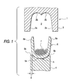
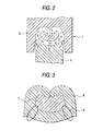
- FIGS. 1 and 2 are views each showing a terminal crimping die system of the invention.
- reference numeral 1 designates a terminal crimping die system.
- This terminal crimping die system 1 consists of a crimper (or upper die) 3, which has a recess 2, and an anvil (or lower die) 4 disposed under the crimper 3.
- the crimper 3 has a recess 2, which is opened in the downward direction of weight, and is provided in such a manner as to be able to move along the direction of gravity.
- the recess 2 has a shape that is nearly bilaterally symmetric with respect to a center line thereof.
- the recess 2 is constituted by guide walls 2a, which are shaped so that the lateral distance therebetween is increased toward the anvil 4, and crimping walls 2b, which are respectively continued from the guide walls 2a and shaped like curved surfaces. That is, the recess 2 is shaped nearly like a reverse W.
- the anvil 4 is disposed in the direction of gravity, that is, under the recess 2 of the crimper 3, and formed in such a way as to have a section shaped so that the anvil 4 can be fitted into the recess 2 of the crimper 3.
- the top surface of the anvil 4 is formed as a crimping face 5.
- a terminal receiving groove 5a, on which a terminal 6 is put, is provided in this crimping face part 14.
- the terminal receiving groove 5a is used by putting the terminal 6 thereon to thereby perform positioning of the terminal 6.
- the shape of the terminal receiving groove 5a is not limited to a specific one. As shown in the figure, the terminal receiving groove 5a may be shaped like a curved groove. Alternatively, the terminal receiving groove 5a may be formed in such a way as to have another shape like a letter, for example, "V".
- Both end parts of the terminal receiving groove 5a are placed at a predetermined distance from end parts of the crimping face 5 toward the center thereof, respectively.
- Each of receiving surfaces 14b each extending along a direction (that is, a horizontal direction) nearly perpendicular to a direction (that is, the downward direction of gravity), in which the anvil 4 is fitted, is provided between a corresponding one of both end parts of the terminal receiving groove 5a and that of both end parts of the crimping face 5. That is, the crimping face 5 is constituted by the receiving surfaces 5 and the terminal receiving groove 5a.
- each of the receiving surfaces 5b (that is, the length between the corresponding one of both end parts of the terminal receiving groove 5a and that of both end parts of the crimping face 5) a is set at a length at which the calking force generated in the vicinity of the receiving surface 5b during crimping the terminal 6 is deconcentrated.
- the width a of each of the receiving surfaces 5b is not more than 1/2 of the (plate) thickness of the terminal 6.
- the width a of each of the receiving surfaces 5b is set at a length ranging from 1/5 to 2/5 of the plate thickness of the terminal 6.
- the terminal 6 which accommodates conductors 7 of electric wires between crimping pieces 6a and 6a and has a U-shaped section, is put on the terminal receiving groove 5a of the anvil 4.
- the crimper 3 is downwardly moved.
- the terminal 6 is downwardly and upwardly pressed by the crimper 3 and the anvil 4, respectively, during lowering the crimper 3.
- Each of the crimping pieces 6a and 6a has a top end, which comes into slide-contact with the guide wall 2a, and is gradually and inwardly pushed and bent as the guide wall 2a is lowered.
- the crimping pieces 6a and 6a enclose the conductors 7 and are crimped and caulked in such a manner as to dig into the conductors 7.
- the caulking force f is generated in each crimping part.
- the caulking force f generated in the vicinity of the receiving surface 5b acts on the receiving surface 5b.
- the width a of each of the receiving surfaces 5b is equal to or less than 1/2 of the (plate) thickness of the terminal 6, so that the receiving surfaces 5b cannot receive all the caulking force f .
- the receiving surfaces 5b thus receive a part f " of the caulking force.
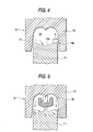
- the remaining caulking force f' acts in the direction of the terminal receiving groove 5a. Therefore, the caulking force f generated in the vicinity of the receiving surfaces 5b is deconcentrated, so that stress is not concentrated on a part of the terminal 6 (that is, the part A shown in FIG. 3).
- the terminal 6 is favorably crimped to an electric wire.
- each of terminals each having a plate thickness of 0.25 mm was crimped onto an electric wire by using an anvil, which had receiving surfaces, whose widths were 0.10 mm and 0.05 mm.
- stress was not concentrated on the part A .
- judgments on the presence or absence of stress were made as follows. That is, when a wrinkle was found by a visual inspection, it was decided that the stress was present. Conversely, when no wrinkles were found by a visual inspection, it was decided that the stress was absent.
- each of the receiving surfaces 5b of the terminal crimping die system of the invention is not more than 1/2 of the (plate) thickness of the terminal 6, a part of the caulking force f generated in the vicinity of the receiving surfaces 5b acts in the direction of the inside of the terminal receiving groove 5a when the terminal 6 is crimped onto an electric wire.
- the caulking force f generated in the vicinity of the receiving surfaces 5b is deconcentrated. Consequently, the terminal 6 can favorably be crimped to the wire without concentrating stress on the terminal 6.
- the electrical connecting performance and the mechanical connecting performance thereof can be enhanced.
- the durability of the terminal 6 can be improved.
- a terminal can favorably be crimped to an electric wire without concentrating stress on a part of a terminal.
Landscapes
- Engineering & Computer Science (AREA)
- Manufacturing & Machinery (AREA)
- Manufacturing Of Electrical Connectors (AREA)
- Connections Effected By Soldering, Adhesion, Or Permanent Deformation (AREA)
Abstract
Description
Claims (4)
- A terminal crimping die system comprising:wherein a width of the receiving surface is not more than 1/2 of a thickness of said terminal.a crimper including a recess; andan anvil provided with a crimping face including a terminal receiving groove and a pair of receiving surfaces, each of which is formed between an end part of the terminal receiving groove and an end part of the crimping face, the anvil being configured to be inserted into the recess of the crimper to thereby crimp and connect a terminal to an electric wire;
- A terminal crimping die system as claimed in claim 1, wherein the width of said receiving surface ranges from 1/5 to 2/5 of the thickness of said terminal.
- A terminal crimping method comprising the steps of:wherein a width of the receiving surface is not more than 1/2 of a thickness of said terminal.providing a crimper including a recess and an anvil provided with a crimping face including a terminal receiving groove and a pair of receiving surfaces, each of which is formed between an end part of the terminal receiving groove and an end part of the crimping face;putting a terminal on the crimping face; andinserting the anvil into the recess of the crimper, so that the terminal is crimped to an electric wire;
- A terminal crimping method as claimed in claim 3, wherein the width of said receiving surface ranges from 1/5 to 2/5 of the thickness of said terminal.
Applications Claiming Priority (2)
| Application Number | Priority Date | Filing Date | Title |
|---|---|---|---|
| JP2001178217 | 2001-06-13 | ||
| JP2001178217A JP4387612B2 (en) | 2001-06-13 | 2001-06-13 | Terminal crimping type |
Publications (3)
| Publication Number | Publication Date |
|---|---|
| EP1267457A2 true EP1267457A2 (en) | 2002-12-18 |
| EP1267457A3 EP1267457A3 (en) | 2003-05-07 |
| EP1267457B1 EP1267457B1 (en) | 2005-09-28 |
Family
ID=19018952
Family Applications (1)
| Application Number | Title | Priority Date | Filing Date |
|---|---|---|---|
| EP02100703A Expired - Lifetime EP1267457B1 (en) | 2001-06-13 | 2002-06-13 | Terminal crimping dies |
Country Status (4)
| Country | Link |
|---|---|
| US (1) | US6813826B2 (en) |
| EP (1) | EP1267457B1 (en) |
| JP (1) | JP4387612B2 (en) |
| DE (1) | DE60206324T2 (en) |
Cited By (5)
| Publication number | Priority date | Publication date | Assignee | Title |
|---|---|---|---|---|
| CN103878271A (en) * | 2014-03-28 | 2014-06-25 | 德清振达电气有限公司 | Die of micromotor fan wire clamping machine |
| CN106618186A (en) * | 2017-01-24 | 2017-05-10 | 徐盈 | Novel electric kettle device |
| CN107157319A (en) * | 2017-01-24 | 2017-09-15 | 徐盈 | A kind of improved electric kettle device |
| CN107157320A (en) * | 2017-01-24 | 2017-09-15 | 徐盈 | A kind of electric kettle device |
| CN108140999A (en) * | 2015-10-21 | 2018-06-08 | 株式会社自动网络技术研究所 | Manufacturing method, crimping jig and the electric wire with terminal of electric wire with terminal |
Families Citing this family (9)
| Publication number | Priority date | Publication date | Assignee | Title |
|---|---|---|---|---|
| JP2001250657A (en) * | 2000-03-03 | 2001-09-14 | Yazaki Corp | Crimping device for crimping pieces of metal terminal fittings |
| JP4818134B2 (en) | 2007-01-18 | 2011-11-16 | 矢崎総業株式会社 | Terminal crimping device |
| JP2008177033A (en) | 2007-01-18 | 2008-07-31 | Yazaki Corp | Terminal crimping device |
| EP2230732B1 (en) * | 2009-03-16 | 2014-04-23 | Delphi Technologies, Inc. | Device for attaching a cable to a connection element |
| WO2011004704A1 (en) | 2009-07-10 | 2011-01-13 | 矢崎総業株式会社 | Terminal crimping device |
| DE102010035424A1 (en) * | 2010-08-26 | 2012-03-01 | Audi Ag | Method for connecting an electrical conductor to an electrical contact part |
| DE102013010981B3 (en) * | 2013-07-01 | 2014-08-28 | Audi Ag | Method and device for connecting an electrical conductor to an electrical contact part |
| JP6569124B2 (en) * | 2015-11-12 | 2019-09-04 | 住友電装株式会社 | Conductive member manufacturing method, conductive member and mold |
| DE102017218486A1 (en) * | 2017-10-16 | 2019-04-18 | Te Connectivity Germany Gmbh | Method and arrangement for producing a crimped connection arrangement, connection arrangement |
Family Cites Families (4)
| Publication number | Priority date | Publication date | Assignee | Title |
|---|---|---|---|---|
| NL120485C (en) | 1960-03-09 | |||
| DE3921990A1 (en) * | 1988-07-08 | 1990-01-11 | Yazaki Corp | PINCH CONNECTOR FOR LADDER AND METHOD FOR PRODUCING A PINCH CONNECTION |
| JP2511123B2 (en) * | 1988-10-13 | 1996-06-26 | 矢崎総業株式会社 | Crimping terminal and connection method of crimping terminal and electric wire |
| JPH0680263U (en) | 1993-04-27 | 1994-11-08 | 矢崎総業株式会社 | Crimp terminal |
-
2001
- 2001-06-13 JP JP2001178217A patent/JP4387612B2/en not_active Expired - Fee Related
-
2002
- 2002-06-12 US US10/166,747 patent/US6813826B2/en not_active Expired - Lifetime
- 2002-06-13 EP EP02100703A patent/EP1267457B1/en not_active Expired - Lifetime
- 2002-06-13 DE DE60206324T patent/DE60206324T2/en not_active Expired - Lifetime
Cited By (6)
| Publication number | Priority date | Publication date | Assignee | Title |
|---|---|---|---|---|
| CN103878271A (en) * | 2014-03-28 | 2014-06-25 | 德清振达电气有限公司 | Die of micromotor fan wire clamping machine |
| CN108140999A (en) * | 2015-10-21 | 2018-06-08 | 株式会社自动网络技术研究所 | Manufacturing method, crimping jig and the electric wire with terminal of electric wire with terminal |
| CN108140999B (en) * | 2015-10-21 | 2019-11-05 | 株式会社自动网络技术研究所 | Manufacturing method, crimping jig and the electric wire with terminal of electric wire with terminal |
| CN106618186A (en) * | 2017-01-24 | 2017-05-10 | 徐盈 | Novel electric kettle device |
| CN107157319A (en) * | 2017-01-24 | 2017-09-15 | 徐盈 | A kind of improved electric kettle device |
| CN107157320A (en) * | 2017-01-24 | 2017-09-15 | 徐盈 | A kind of electric kettle device |
Also Published As
| Publication number | Publication date |
|---|---|
| JP4387612B2 (en) | 2009-12-16 |
| JP2002373755A (en) | 2002-12-26 |
| DE60206324D1 (en) | 2005-11-03 |
| DE60206324T2 (en) | 2006-03-23 |
| US6813826B2 (en) | 2004-11-09 |
| EP1267457A3 (en) | 2003-05-07 |
| US20020189095A1 (en) | 2002-12-19 |
| EP1267457B1 (en) | 2005-09-28 |
Similar Documents
| Publication | Publication Date | Title |
|---|---|---|
| EP0501629B1 (en) | Cable strain relief back shell | |
| EP1267457B1 (en) | Terminal crimping dies | |
| US6749457B2 (en) | Crimp terminal | |
| US4277124A (en) | Connector having wire-in-slot connecting means and crimped strain relief | |
| US7775842B2 (en) | Crimping structure and crimping method | |
| JP5311962B2 (en) | Crimp terminal for aluminum wire and method for manufacturing crimp terminal for aluminum wire | |
| JPH0680263U (en) | Crimp terminal | |
| JPH11219769A (en) | Terminal and mold for forming it | |
| US11848527B2 (en) | Terminal | |
| US7244139B2 (en) | Electric connector and method for manufacturing the same | |
| EP0057780A1 (en) | Electrical connector with a terminal having a slotted wire receiving portion and wire strain relief means | |
| JPH0817544A (en) | Barrel terminal and wire connection device | |
| EP0600402B1 (en) | Electrical connector with improved terminal retention | |
| US6540544B1 (en) | Press-connecting connector and wire press-fitting apparatus | |
| US5186658A (en) | Electrical contact | |
| EP0446220B1 (en) | Electrical contact | |
| JPH10302857A (en) | Electrical connector | |
| WO1998054790A1 (en) | Crimp connection for large conductors | |
| JP5125941B2 (en) | Terminal crimping device | |
| EP0608836A2 (en) | Electrical terminal receptacle with improved means for connecting two electrical conducting cables and a method for manufacturing it | |
| EP2187478A1 (en) | A terminal fitting, a wire connection structure and a connecting method | |
| EP0951095A2 (en) | Electrical connector | |
| WO1996033528A1 (en) | Temporary terminal retention feature | |
| JPH0534693U (en) | Crimping die for crimp terminals | |
| EP0755096A1 (en) | A female terminal metal fittings and a preparing method thereof |
Legal Events
| Date | Code | Title | Description |
|---|---|---|---|
| PUAI | Public reference made under article 153(3) epc to a published international application that has entered the european phase |
Free format text: ORIGINAL CODE: 0009012 |
|
| AK | Designated contracting states |
Kind code of ref document: A2 Designated state(s): DE FR GB |
|
| AX | Request for extension of the european patent |
Free format text: AL;LT;LV;MK;RO;SI |
|
| PUAL | Search report despatched |
Free format text: ORIGINAL CODE: 0009013 |
|
| AK | Designated contracting states |
Designated state(s): DE FR GB |
|
| AX | Request for extension of the european patent |
Extension state: AL LT LV MK RO SI |
|
| 17P | Request for examination filed |
Effective date: 20031024 |
|
| AKX | Designation fees paid |
Designated state(s): DE FR GB |
|
| 17Q | First examination report despatched |
Effective date: 20040127 |
|
| GRAP | Despatch of communication of intention to grant a patent |
Free format text: ORIGINAL CODE: EPIDOSNIGR1 |
|
| GRAS | Grant fee paid |
Free format text: ORIGINAL CODE: EPIDOSNIGR3 |
|
| GRAA | (expected) grant |
Free format text: ORIGINAL CODE: 0009210 |
|
| AK | Designated contracting states |
Kind code of ref document: B1 Designated state(s): DE FR GB |
|
| REG | Reference to a national code |
Ref country code: GB Ref legal event code: FG4D |
|
| REF | Corresponds to: |
Ref document number: 60206324 Country of ref document: DE Date of ref document: 20051103 Kind code of ref document: P |
|
| ET | Fr: translation filed | ||
| PLBE | No opposition filed within time limit |
Free format text: ORIGINAL CODE: 0009261 |
|
| STAA | Information on the status of an ep patent application or granted ep patent |
Free format text: STATUS: NO OPPOSITION FILED WITHIN TIME LIMIT |
|
| 26N | No opposition filed |
Effective date: 20060629 |
|
| REG | Reference to a national code |
Ref country code: FR Ref legal event code: PLFP Year of fee payment: 15 |
|
| REG | Reference to a national code |
Ref country code: FR Ref legal event code: PLFP Year of fee payment: 16 |
|
| REG | Reference to a national code |
Ref country code: FR Ref legal event code: PLFP Year of fee payment: 17 |
|
| PGFP | Annual fee paid to national office [announced via postgrant information from national office to epo] |
Ref country code: DE Payment date: 20190528 Year of fee payment: 18 |
|
| PGFP | Annual fee paid to national office [announced via postgrant information from national office to epo] |
Ref country code: FR Payment date: 20190510 Year of fee payment: 18 |
|
| PGFP | Annual fee paid to national office [announced via postgrant information from national office to epo] |
Ref country code: GB Payment date: 20190612 Year of fee payment: 18 |
|
| REG | Reference to a national code |
Ref country code: DE Ref legal event code: R119 Ref document number: 60206324 Country of ref document: DE |
|
| GBPC | Gb: european patent ceased through non-payment of renewal fee |
Effective date: 20200613 |
|
| PG25 | Lapsed in a contracting state [announced via postgrant information from national office to epo] |
Ref country code: FR Free format text: LAPSE BECAUSE OF NON-PAYMENT OF DUE FEES Effective date: 20200630 Ref country code: GB Free format text: LAPSE BECAUSE OF NON-PAYMENT OF DUE FEES Effective date: 20200613 |
|
| PG25 | Lapsed in a contracting state [announced via postgrant information from national office to epo] |
Ref country code: DE Free format text: LAPSE BECAUSE OF NON-PAYMENT OF DUE FEES Effective date: 20210101 |