EP1267448A2 - Dual-polarization common aperture antenna with longitudinal and transverse slot arrays - Google Patents
Dual-polarization common aperture antenna with longitudinal and transverse slot arrays Download PDFInfo
- Publication number
- EP1267448A2 EP1267448A2 EP02254081A EP02254081A EP1267448A2 EP 1267448 A2 EP1267448 A2 EP 1267448A2 EP 02254081 A EP02254081 A EP 02254081A EP 02254081 A EP02254081 A EP 02254081A EP 1267448 A2 EP1267448 A2 EP 1267448A2
- Authority
- EP
- European Patent Office
- Prior art keywords
- array
- slots
- slot
- common aperture
- stripline
- Prior art date
- Legal status (The legal status is an assumption and is not a legal conclusion. Google has not performed a legal analysis and makes no representation as to the accuracy of the status listed.)
- Ceased
Links
Images


Classifications
-
- H—ELECTRICITY
- H01—ELECTRIC ELEMENTS
- H01Q—ANTENNAS, i.e. RADIO AERIALS
- H01Q21/00—Antenna arrays or systems
- H01Q21/0006—Particular feeding systems
-
- H—ELECTRICITY
- H01—ELECTRIC ELEMENTS
- H01Q—ANTENNAS, i.e. RADIO AERIALS
- H01Q21/00—Antenna arrays or systems
- H01Q21/06—Arrays of individually energised antenna units similarly polarised and spaced apart
- H01Q21/061—Two dimensional planar arrays
- H01Q21/064—Two dimensional planar arrays using horn or slot aerials
-
- H—ELECTRICITY
- H01—ELECTRIC ELEMENTS
- H01Q—ANTENNAS, i.e. RADIO AERIALS
- H01Q21/00—Antenna arrays or systems
- H01Q21/24—Combinations of antenna units polarised in different directions for transmitting or receiving circularly and elliptically polarised waves or waves linearly polarised in any direction
Definitions
- the present invention relates to antennas. More specifically, the present invention relates to radio frequency (radar) antennas for missile seekers and other applications.
- radar radio frequency
- Radio frequency (RF) antennas are used in many communication, ranging and detection (radar) applications.
- the RF antenna is implemented as part of a missile seeker.
- the seeker comprises the antenna along with a transmitter and a receiver.
- missile seekers transmit and receive a beam having a single polarization.
- the polarization of a beam is the orientation of the electric field thereof.
- the polarization of a beam may be vertical, horizontal or circular.
- dual polarization antennas are known in the art.
- One is a reflector antenna with dual polarization feed.
- This type of antenna is bulky, exhibits poor efficiency, and poor isolation between the two polarizations.
- This type of antenna is also very limited in its ability offer low sidelobe radiation performance.
- this type antenna can generally be used only for an electrically very large aperture (i.e. an aperture having a diameter larger than fifteen wavelengths).
- a second approach involves the use of an array of dual polarized patches.
- This type of antenna offers low cost and low profile, but the bandwidth of each element is typically so narrow that it is very difficult to achieve high performance.
- the efficiency of this array is also typically poor due to dielectric losses and stripline conductor losses.
- a third approach involves the use of a dual polarization rectangular waveguide array consisting of a stack-up of a rectangular waveguide-fed offset longitudinal slot array and a waveguide-fed tilted edge slot array.
- this array exhibits poor performance because the offset slot excites an undesirable TM 01 odd mode in the parallel plate region formed by the tilted edge slot waveguides.
- the excited TM 01 odd mode causes high sidelobes and RF loss.
- a further performance limitation results from the coupling between apertures caused by the tilted edge slot containing a cross-polarization component.
- a fourth approach involves the use of an arched notch dipole card array erected over a rectangular waveguide fed offset longitudinal slot array.
- the arch is provided to improve the performance of the principal polarization slot array and minimize interactions between the two apertures.
- the design of this type of array is very difficult because there is no easy or convenient method to account for the presence of the arched dipole array in the design of the slot array (every slot sees a different unit cell).
- the requirement to maximize the spacing between the face of the slot array and the arch cards to reduce interaction conflicts with the desired placement of the notch radiators on the quarter-wavelength above this surface for optimal image current formation. This limitation becomes especially severe at higher frequencies of operation.
- a fifth approach involves the use of a common aperture for dual polarization array with a flat plate centered longitudinal shunt slot array and a striplinefed notch-dipole array.
- This approach was disclosed and claimed in U.S. Patent No. 6,166,701 issued December 26, 2000 to Pyong K. Park et al. and entitled DUAL POLARIZATION ANTENNA ARRAY WITH RADIATING SLOTS AND NOTCH DIPOLE ELEMENTS SHARING A COMMON APERTURE (Atty. Docket No. PD-96309) the teachings of which are incorporated herein by reference.
- This approach is very useful for very high frequency (Ka-band or higher) applications and electrically medium to large size arrays.
- the dipole card height is greater than a half-inch, which is often more than the available antenna depth. Therefore, it may not be practical to use this approach for lower frequency applications and electrically small to medium size antennas.
- the inventive antenna includes a first and second arrays of radiating slots disposed in a faceplate.
- the second array is generally orthogonal and therefor cross-polarized relative to the first array.
- the first array is waveguide fed and the second array is inverted micro-stripline fed.
- the first array and the second array share a common aperture.
- the common aperture is fully populated and each array uses the aperture in its entirety.
- the first and second arrays of slots are arranged for four-way symmetry.
- Each slot in the first array is a horizontally oriented, iris-excited shunt slot fed by a rectangular waveguide and centered on a broad wall thereof.
- the second array is a standing wave array in which each slot is an air cavity backed slot fed by an inverted micro-stripline offset from a center thereof.
- the current invention provides such an antenna.
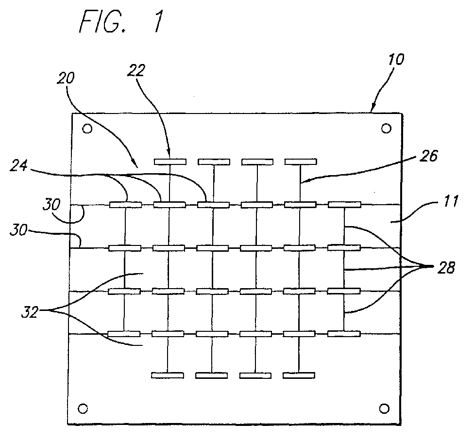
- Fig. 1 is a front view of the dual-polarization common aperture antenna of the present invention.
- the antenna is constructed of a unitary block of aluminum or other suitable material.
- the antenna 10 has a faceplate 11 and a backplate 13 (not shown in Fig. 1).
- the antenna 10 has a common aperture 20 fully populated with elements for both polarizations and provides high gain and low sidelobe performance for both polarizations.
- Within the aperture 20 a first array 22 of horizontally oriented radiating slots 24 and an orthogonally polarized second array 26 of vertically oriented radiating slots 28 are provided.
- the first slots 24 are disposed in channels or recesses 30 in the faceplate 11 of the antenna.
- the slots and the recesses are machined into the antenna using techniques well known in the art.
- the waveguide slot channels 30 contribute a simple means to maintain a thin wall in the vicinity of the radiating slots, while simultaneously providing a thick broad wall 34 with which to totally accommodate the array two packaging needs.
- the horizontal slots 24 are spaced .7 wavelength (.7 ⁇ ) apart with respect to the desired operating frequency of the antenna.
- the vertical slots 28 are spaced at .7 ⁇ .
- Fig. 2 is a diagram of a single channel of the inventive antenna showing the horizontal slots 24 therein.
- each of the horizontal slots 24 in the first (main) array 22 is an iris-excited longitudinal shunt slot fed by a rectangular waveguide 32.
- the waveguide 32 is collinear with the horizontal slots 24 along a transverse axis 33 of the antenna 10.
- the slots 24 are centered on the broad walls 34 of the waveguides 32 to provide room for the second (cross-polarization) array 26.
- Each iris 35 consists of a capacitive element 36 and an inductive element 38.
- the capacitive element 36 consists of a small sheet of conductive material disposed within the waveguide 32 transverse to the longitudinal axis thereof and below an associated slot 24.
- the inductive element 38 is a small sheet of conductive material mounted within the waveguide 32 transverse to the longitudinal axis thereof and below the associated slot 24.
- Fig. 3 is a sectional rear view of the dual-polarization common aperture antenna of the present invention showing the backplate 13 thereof with the ground plane removed.
- the cross-polarization array 26 is realized with an efficient standing wave array of inverted micro-stripline-fed air-cavity backed slots 28.
- Each slot 28 is fed by one of six input ports 40, 42, 46, 48, 50 or 52.
- the first four ports 40, 42, 46, and 48, respectively, are located at corners of the aperture 20 while the fifth and sixth ports 50 and 52, respectively, are provided above and below the centerline of the aperture 20.
- Each of the first four ports 40, 42, 46, and 48 feeds an associated micro-strip power divider 54.
- the power divider 54 has a first output line 56 and a second output line 58.
- the first output line 56 feeds two vertical slots 28. Note the provision of a perturbation 59 in the line to adjust the line length thereof.
- the second output line 58 of each of the first four ports feeds a second power divider 60.
- the second power divider 60 has two output lines 62 and 64.
- the first line of the second power divider feeds two vertical slots 28 while the second line 64 feeds a single slot 28.
- the ports 50 and 52 feed lines 51 and 53, respectively, each of which, in turn, feed three vertical slots 28.
- the lines 51, 53, 56, 58, 62 and 64 are inverted micro-striplines.
- Fig. 4 is a magnified view of a section of the second array 26 of the inventive antenna showing the inverted micro-stripline traces thereon.
- micro-striplines are striplines in which the signal return energy is constrained to flow in a single ground plane.
- Inverted micro-striplines are micro-striplines which are enclosed within conductive channels in which the energy flows in the ground plane above the surface of the trace as well as to the ground plane on the surface of the backplate 13 (not shown).
- the micro-striplines are bonded to the surface of the faceplate 11 in a conventional manner.
- Fig. 5 is a perspective sectional view showing two channels in the inventive antenna.
- the channels 30 are machined into the front of the thick wall of the first array 22 below each of the vertical slots 24.
- the channels 30 are machined into the thick wall 34 of the faceplate 11 to provide room for the air cavity backed slots and their associated interconnecting transmission lines.
- the channels 30 contain provisions for mounting and locating the printed circuit boards in a manner which places the radiating slot ground plane at the same position as the top of the channels associated with the main array slots, thus minimizing discontinuities in the ground plane and preserving full performance of the main array.
- the channels which form the cross pol radiating slots are symmetrically located between the main array slots.
- the interconnecting transmission lines which feed the array 2 feed network are isolated from one another in channels to eliminate the undesired affect of cross talk or radiation.
- the radiation of each cross-polarization (vertical) slot 28 is controlled by offset of the microstrip feed line from the center of slot.
- air cavities 66 and 68 are provided to improve the RF bandwidth of the radiating slots 28.
- the slot spacing for cross-polarization array 26 must be the same as the principal polarization array 22 spacing, which is about 0.7 ⁇ .
- the cross-polarization slot spacing in the micro-strip medium has to be one wavelength apart to form a collimated radiation pattern.
- the micro-stripline offers a proper propagation constant such that 0.7 ⁇ in free space is equivalent to 0.9 ⁇ in micro-stripline.
- the slot arrangement for both arrays exhibits four-way symmetry, which provides good isolation between the two orthogonally polarized arrays. Optimal electrical isolation between the two arrays is achieved as a result of the mutually orthogonal slot geometries.
- Both arrays 22 and 26 of the antenna 10 utilize the entire aperture 20 to maximize performance.
- the inventive antenna realizes both arrays in efficient standing wave array configurations to concurrently achieve high gain and low sidelobe levels.
- a particularly novel feature of this invention is the concurrent realization of a high-performance dual polarization common aperture antenna array within a small cross sectional profile. This is achieved by using rectangular wave-guide-fed centered longitudinal shunt slots in conjunction with inverted micro-stripline-fed air-cavity-backed slots within the same design geometry.
- This inventive antenna design offers the following advantages relative to other approaches:
Landscapes
- Variable-Direction Aerials And Aerial Arrays (AREA)
- Waveguide Aerials (AREA)
Abstract
Description
Claims (20)
- A dual-polarization common aperture antenna characterized by:a first array (22) of radiating slots (24) disposed in a faceplate (11);a waveguide (32) for feeding electromagnetic energy to said first array (22) of radiating slots (24);a second array (26) of radiating slots (28) disposed in said faceplate (13), said second array (26) being generally orthogonal to said first array (22) of radiating slots; anda stripline (51, 53, 56, 58, 62 and 64) for feeding said second array (26) of radiating slots (28).
- The invention of Claim 1 wherein each slot (24) in said first array (22) of radiating slots is vertically oriented.
- The invention of Claim 2 wherein each of said slots (24) in said first array of slots is a shunt slot.
- The invention of Claim 3 wherein each slot (24) in said first array of slots is iris-excited.
- The invention of Claim 4 wherein each slot (24) is excited by a ridge iris (35).
- The invention of Claim 1 wherein said waveguide (32) is rectangular.
- The invention of Claim 1 wherein said second array (26) of slots radiates cross-polarized relative to said first array (22) of slots.
- The invention of Claim 1 wherein said second array (26) of slots is a standing wave array.
- The invention of Claim 1 wherein said stripline (51, 53, 56, 58, 62 and 64) is a micro-stripline.
- The invention of Claim 9 wherein said stripline (51, 53, 56, 58, 62 and 64) is an inverted micro-stripline.
- The invention of Claim 9 wherein said micro-stripline (51, 53, 56, 58, 62 and 64) is offset from a center of at least one of said radiating slots (28) in said second array (26) of slots.
- The invention of Claim 1 wherein said stripline (51, 53, 56, 58, 62 and 64) has a perturbation (59) therein to increase the length thereof.
- The invention of Claim 12 wherein said slots (28) in said second array (26) are spaced one wavelength apart with respect to said electromagnetic energy.
- The invention of Claim 1 wherein each slot (28) in said second array (26) of slots is an air cavity backed slot.
- The invention of Claim 1 wherein said first array (22) and said second array (26) share a common aperture (20).
- The invention of Claim 15 wherein said first array (22) and said second array (26) each utilize said common aperture (20) in its entirety.
- The invention of Claim 15 wherein said common aperture (20) is fully populated.
- The invention of Claim 1 wherein said first array (22) utilizes said common aperture (20) in its entirety.
- The invention of Claim 18 wherein said second array (260 utilizes said common aperture (20) in its entirety.
- The invention of Claim 1 wherein the first array (22) and said second array (26) of slots are arranged for four-way symmetry.
Applications Claiming Priority (2)
| Application Number | Priority Date | Filing Date | Title |
|---|---|---|---|
| US880423 | 2001-06-13 | ||
| US09/880,423 US6731241B2 (en) | 2001-06-13 | 2001-06-13 | Dual-polarization common aperture antenna with rectangular wave-guide fed centered longitudinal slot array and micro-stripline fed air cavity back transverse series slot array |
Publications (2)
| Publication Number | Publication Date |
|---|---|
| EP1267448A2 true EP1267448A2 (en) | 2002-12-18 |
| EP1267448A3 EP1267448A3 (en) | 2004-03-17 |
Family
ID=25376250
Family Applications (1)
| Application Number | Title | Priority Date | Filing Date |
|---|---|---|---|
| EP02254081A Ceased EP1267448A3 (en) | 2001-06-13 | 2002-06-12 | Dual-polarization common aperture antenna with longitudinal and transverse slot arrays |
Country Status (3)
| Country | Link |
|---|---|
| US (1) | US6731241B2 (en) |
| EP (1) | EP1267448A3 (en) |
| IL (1) | IL150162A0 (en) |
Cited By (5)
| Publication number | Priority date | Publication date | Assignee | Title |
|---|---|---|---|---|
| WO2005074073A1 (en) * | 2004-01-15 | 2005-08-11 | Raytheon Company | Antenna arrays using long slot apertures and balanced feeds |
| US7071872B2 (en) | 2002-06-18 | 2006-07-04 | Bae Systems Plc | Common aperture antenna |
| CN102237570A (en) * | 2010-04-09 | 2011-11-09 | 古野电气株式会社 | Antenna device and radar apparatus |
| WO2017175155A1 (en) * | 2016-04-05 | 2017-10-12 | Alcatel-Lucent Shanghai Bell Co.,Ltd | Broadband cavity-backed slot antenna |
| RU2861329C2 (en) * | 2023-05-04 | 2026-05-04 | Чэнду Сателлайт Коммуникейшн Кооперейшн Текнолоджи Ко., Лтд. | Dual-band dual-polarisation planar antenna with shared aperture based on "double cross" waveguide structure |
Families Citing this family (35)
| Publication number | Priority date | Publication date | Assignee | Title |
|---|---|---|---|---|
| JP2006029834A (en) * | 2004-07-13 | 2006-02-02 | Hitachi Ltd | Automotive radar |
| US7379029B2 (en) | 2005-09-27 | 2008-05-27 | Elta Systems Ltd | Waveguide slot antenna and arrays formed thereof |
| US7830322B1 (en) | 2007-09-24 | 2010-11-09 | Impinj, Inc. | RFID reader antenna assembly |
| US8098189B1 (en) * | 2008-09-23 | 2012-01-17 | Rockwell Collins, Inc. | Weather radar system and method using dual polarization antenna |
| JP5731745B2 (en) * | 2009-10-30 | 2015-06-10 | 古野電気株式会社 | Antenna device and radar device |
| JP5135317B2 (en) * | 2009-11-04 | 2013-02-06 | 株式会社ホンダエレシス | On-vehicle radar device and program |
| JP5486382B2 (en) * | 2010-04-09 | 2014-05-07 | 古野電気株式会社 | Two-dimensional slot array antenna, feeding waveguide, and radar apparatus |
| US8274425B2 (en) * | 2010-12-29 | 2012-09-25 | Raytheon Company | Single channel semi-active radar seeker |
| WO2012139079A2 (en) | 2011-04-07 | 2012-10-11 | Colburn Joseph S | Tunable impedance surfaces |
| US9407239B2 (en) | 2011-07-06 | 2016-08-02 | Hrl Laboratories, Llc | Wide bandwidth automatic tuning circuit |
| US9160049B2 (en) | 2011-11-16 | 2015-10-13 | Commscope Technologies Llc | Antenna adapter |
| US8866687B2 (en) | 2011-11-16 | 2014-10-21 | Andrew Llc | Modular feed network |
| US8558746B2 (en) | 2011-11-16 | 2013-10-15 | Andrew Llc | Flat panel array antenna |
| US9184507B2 (en) | 2012-03-23 | 2015-11-10 | Lhc2 Inc | Multi-slot common aperture dual polarized omni-directional antenna |
| US10103445B1 (en) * | 2012-06-05 | 2018-10-16 | Hrl Laboratories, Llc | Cavity-backed slot antenna with an active artificial magnetic conductor |
| DE102013012315B4 (en) * | 2013-07-25 | 2018-05-24 | Airbus Defence and Space GmbH | Waveguide radiators. Group Antenna Emitter and Synthetic Aperture Radar System |
| US9705201B2 (en) | 2014-02-24 | 2017-07-11 | Hrl Laboratories, Llc | Cavity-backed artificial magnetic conductor |
| CN105612660B (en) | 2014-02-27 | 2019-10-22 | 华为技术有限公司 | A common aperture antenna and base station |
| US10181645B1 (en) * | 2016-09-06 | 2019-01-15 | Aeroantenna Technology, Inc. | Dual KA band compact high efficiency CP antenna cluster with dual band compact diplexer-polarizers for aeronautical satellite communications |
| US9425769B1 (en) | 2014-07-18 | 2016-08-23 | Hrl Laboratories, Llc | Optically powered and controlled non-foster circuit |
| US20170229785A1 (en) * | 2014-10-10 | 2017-08-10 | Commscope Technologies Llc | Stadium antenna |
| US10031191B1 (en) | 2015-01-16 | 2018-07-24 | Hrl Laboratories, Llc | Piezoelectric magnetometer capable of sensing a magnetic field in multiple vectors |
| WO2016095064A1 (en) * | 2015-10-13 | 2016-06-23 | Serani Mostazal Jorge | Aperture antenna array, method and system for locating, tracking, detecting and controlling the access of people and objects |
| CN106785365A (en) * | 2015-12-22 | 2017-05-31 | 中国电子科技集团公司第二十研究所 | The common aperture navigation antenna of double-fed double frequency |
| US10191152B2 (en) * | 2016-07-29 | 2019-01-29 | Honeywell International Inc. | Low-cost lightweight integrated antenna for airborne weather radar |
| CN109841963B (en) * | 2017-11-28 | 2021-06-15 | 华为技术有限公司 | A feeder system, antenna system and base station |
| KR102486593B1 (en) | 2017-12-19 | 2023-01-10 | 삼성전자 주식회사 | Antenna module supproting radiation of vertical polarization and electric device including the antenna module |
| US10852390B2 (en) * | 2017-12-20 | 2020-12-01 | Waymo Llc | Multiple polarization radar unit |
| WO2019186238A1 (en) * | 2018-03-29 | 2019-10-03 | Telefonaktiebolaget Lm Ericsson (Publ) | Single and dual polarized dual-resonant cavity backed slot antenna (d-cbsa) elements |
| US10749268B2 (en) * | 2018-12-14 | 2020-08-18 | GM Global Technology Operations LLC | Aperture-coupled microstrip antenna array |
| KR102607579B1 (en) | 2018-12-31 | 2023-11-30 | 삼성전자주식회사 | An electronic device including a multi band antenna |
| US11024952B1 (en) | 2019-01-25 | 2021-06-01 | Hrl Laboratories, Llc | Broadband dual polarization active artificial magnetic conductor |
| CN112467346B (en) * | 2020-10-28 | 2022-07-19 | 武汉虹信科技发展有限责任公司 | Integrated dual-polarized ceiling antenna |
| GB2618462A (en) * | 2021-02-19 | 2023-11-08 | Alps Alpine Co Ltd | Microstrip antenna |
| KR102416476B1 (en) * | 2021-07-28 | 2022-07-05 | 주식회사 에이티코디 | Radar module using multi polarization |
Family Cites Families (10)
| Publication number | Priority date | Publication date | Assignee | Title |
|---|---|---|---|---|
| US3691563A (en) * | 1970-12-11 | 1972-09-12 | Motorola Inc | Dual band stripline antenna |
| US4243990A (en) * | 1979-04-30 | 1981-01-06 | International Telephone And Telegraph Corporation | Integrated multiband array antenna |
| US4716415A (en) * | 1984-12-06 | 1987-12-29 | Kelly Kenneth C | Dual polarization flat plate antenna |
| DE3915048A1 (en) * | 1989-05-08 | 1990-11-15 | Siemens Ag | Electronically phase controlled antenna - has antenna elements in groups coupled to distributors with polariser switches |
| US5023623A (en) * | 1989-12-21 | 1991-06-11 | Hughes Aircraft Company | Dual mode antenna apparatus having slotted waveguide and broadband arrays |
| US4967167A (en) * | 1990-02-05 | 1990-10-30 | The United States Of America As Represented By The Secretary Of The Army | Microwave transmission line and method of modulating the phase of a signal passed through said line |
| SE510082C2 (en) * | 1993-11-30 | 1999-04-19 | Saab Ericsson Space Ab | Waveguide antenna with transverse and longitudinal slots |
| US5619216A (en) * | 1995-06-06 | 1997-04-08 | Hughes Missile Systems Company | Dual polarization common aperture array formed by waveguide-fed, planar slot array and linear short backfire array |
| US6201507B1 (en) * | 1998-04-09 | 2001-03-13 | Raytheon Company | Centered longitudinal shunt slot fed by a resonant offset ridge iris |
| US6166701A (en) * | 1999-08-05 | 2000-12-26 | Raytheon Company | Dual polarization antenna array with radiating slots and notch dipole elements sharing a common aperture |
-
2001
- 2001-06-13 US US09/880,423 patent/US6731241B2/en not_active Expired - Lifetime
-
2002
- 2002-06-11 IL IL15016202A patent/IL150162A0/en unknown
- 2002-06-12 EP EP02254081A patent/EP1267448A3/en not_active Ceased
Cited By (7)
| Publication number | Priority date | Publication date | Assignee | Title |
|---|---|---|---|---|
| US7071872B2 (en) | 2002-06-18 | 2006-07-04 | Bae Systems Plc | Common aperture antenna |
| WO2005074073A1 (en) * | 2004-01-15 | 2005-08-11 | Raytheon Company | Antenna arrays using long slot apertures and balanced feeds |
| CN102237570A (en) * | 2010-04-09 | 2011-11-09 | 古野电气株式会社 | Antenna device and radar apparatus |
| CN102237570B (en) * | 2010-04-09 | 2015-02-18 | 古野电气株式会社 | Antenna device and radar apparatus |
| WO2017175155A1 (en) * | 2016-04-05 | 2017-10-12 | Alcatel-Lucent Shanghai Bell Co.,Ltd | Broadband cavity-backed slot antenna |
| US10998636B2 (en) | 2016-04-05 | 2021-05-04 | Nokia Shanghai Bell Co., Ltd | Broadband cavity-backed slot antenna |
| RU2861329C2 (en) * | 2023-05-04 | 2026-05-04 | Чэнду Сателлайт Коммуникейшн Кооперейшн Текнолоджи Ко., Лтд. | Dual-band dual-polarisation planar antenna with shared aperture based on "double cross" waveguide structure |
Also Published As
| Publication number | Publication date |
|---|---|
| IL150162A0 (en) | 2002-12-01 |
| EP1267448A3 (en) | 2004-03-17 |
| US6731241B2 (en) | 2004-05-04 |
| US20040056814A1 (en) | 2004-03-25 |
Similar Documents
| Publication | Publication Date | Title |
|---|---|---|
| US6731241B2 (en) | Dual-polarization common aperture antenna with rectangular wave-guide fed centered longitudinal slot array and micro-stripline fed air cavity back transverse series slot array | |
| US6166701A (en) | Dual polarization antenna array with radiating slots and notch dipole elements sharing a common aperture | |
| EP0747994B1 (en) | Dual polarization common aperture array formed by a waveguide-fed, planar slot array and a linear short backfire array | |
| US5043738A (en) | Plural frequency patch antenna assembly | |
| KR102693697B1 (en) | Microstrip antenna device having a center-fed antenna array | |
| US5160936A (en) | Multiband shared aperture array antenna system | |
| CN112290227B (en) | Dual-frequency dual-circularly-polarized antenna array | |
| JP3029231B2 (en) | Double circularly polarized TEM mode slot array antenna | |
| US10978812B2 (en) | Single layer shared aperture dual band antenna | |
| CN112993538B (en) | Dual polarized antenna, dual polarized array antenna and radar system | |
| KR20020037003A (en) | Leaky-wave dual polarized slot type antenna | |
| EP3972057A1 (en) | Dual polarized antenna using shift series feed | |
| EP4266502B1 (en) | Antenna structure, electronic device and wireless network system | |
| CN117080757A (en) | Design method of left-right circular polarization switchable microstrip array antenna | |
| CN118073849B (en) | Millimeter wave wide angle scanning array antenna based on complementary source and suspension decoupling super surface | |
| CN113991294B (en) | A millimeter wave dual polarization antenna unit | |
| CN114843772A (en) | A dual frequency, dual circular polarization, high isolation Fabry-Perot cavity MIMO antenna and its processing method | |
| JPH10190351A (en) | Millimeter wave band planar antenna | |
| KR20200132618A (en) | Dual Polarization Antenna Using Shift Series Feed | |
| CN117543190A (en) | Shared antenna of SIW single pulse gap array and microstrip patch structure | |
| CN116937132A (en) | Radiating element of antenna, antenna and electronic equipment | |
| CN224082696U (en) | Small dual-polarized millimeter wave antenna | |
| CN115411513B (en) | Large-frequency-ratio dual-function radio frequency equipment and wireless transmission system | |
| CN120357192B (en) | A dual-band high-gain metasurface antenna for radar imaging | |
| US20260066547A1 (en) | Antenna structure and communication device |
Legal Events
| Date | Code | Title | Description |
|---|---|---|---|
| PUAI | Public reference made under article 153(3) epc to a published international application that has entered the european phase |
Free format text: ORIGINAL CODE: 0009012 |
|
| AK | Designated contracting states |
Kind code of ref document: A2 Designated state(s): AT BE CH CY DE DK ES FI FR GB GR IE IT LI LU MC NL PT SE TR |
|
| AX | Request for extension of the european patent |
Free format text: AL;LT;LV;MK;RO;SI |
|
| PUAL | Search report despatched |
Free format text: ORIGINAL CODE: 0009013 |
|
| AK | Designated contracting states |
Kind code of ref document: A3 Designated state(s): AT BE CH CY DE DK ES FI FR GB GR IE IT LI LU MC NL PT SE TR |
|
| AX | Request for extension of the european patent |
Extension state: AL LT LV MK RO SI |
|
| 17P | Request for examination filed |
Effective date: 20040825 |
|
| AKX | Designation fees paid |
Designated state(s): DE FR GB |
|
| 17Q | First examination report despatched |
Effective date: 20050217 |
|
| STAA | Information on the status of an ep patent application or granted ep patent |
Free format text: STATUS: THE APPLICATION HAS BEEN REFUSED |
|
| 18R | Application refused |
Effective date: 20060910 |