EP1267351A2 - Disc cartridge - Google Patents
Disc cartridge Download PDFInfo
- Publication number
- EP1267351A2 EP1267351A2 EP02252207A EP02252207A EP1267351A2 EP 1267351 A2 EP1267351 A2 EP 1267351A2 EP 02252207 A EP02252207 A EP 02252207A EP 02252207 A EP02252207 A EP 02252207A EP 1267351 A2 EP1267351 A2 EP 1267351A2
- Authority
- EP
- European Patent Office
- Prior art keywords
- disc
- cartridge
- case
- disc cartridge
- contact portion
- Prior art date
- Legal status (The legal status is an assumption and is not a legal conclusion. Google has not performed a legal analysis and makes no representation as to the accuracy of the status listed.)
- Granted
Links
- 238000000034 method Methods 0.000 description 5
- 230000003287 optical effect Effects 0.000 description 2
- 235000012489 doughnuts Nutrition 0.000 description 1
- 230000000694 effects Effects 0.000 description 1
- 238000002347 injection Methods 0.000 description 1
- 239000007924 injection Substances 0.000 description 1
- 238000007689 inspection Methods 0.000 description 1
Images


Classifications
-
- G—PHYSICS
- G11—INFORMATION STORAGE
- G11B—INFORMATION STORAGE BASED ON RELATIVE MOVEMENT BETWEEN RECORD CARRIER AND TRANSDUCER
- G11B23/00—Record carriers not specific to the method of recording or reproducing; Accessories, e.g. containers, specially adapted for co-operation with the recording or reproducing apparatus ; Intermediate mediums; Apparatus or processes specially adapted for their manufacture
- G11B23/02—Containers; Storing means both adapted to cooperate with the recording or reproducing means
- G11B23/03—Containers for flat record carriers
- G11B23/0301—Details
- G11B23/0306—Means for locking the record carriers
-
- G—PHYSICS
- G11—INFORMATION STORAGE
- G11B—INFORMATION STORAGE BASED ON RELATIVE MOVEMENT BETWEEN RECORD CARRIER AND TRANSDUCER
- G11B23/00—Record carriers not specific to the method of recording or reproducing; Accessories, e.g. containers, specially adapted for co-operation with the recording or reproducing apparatus ; Intermediate mediums; Apparatus or processes specially adapted for their manufacture
- G11B23/02—Containers; Storing means both adapted to cooperate with the recording or reproducing means
- G11B23/03—Containers for flat record carriers
- G11B23/0301—Details
- G11B23/0307—Positioning or centering features
Definitions
- the present invention relates to a disc cartridge, and more particularly, to a disc cartridge having a means for centering a disc accommodated in the disc cartridge not to be deviated much from the center of a case.
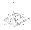
- Figure 1 is a perspective view showing a cartridge loaded and unloaded in a slot-in manner, in which a shutter is open.
- a disc cartridge 1 includes a case 3 forming the outer appearance.
- a circular inner wall 4 encompassing a space where a disc D is placed is formed in the case 3.
- the circular inner wall 4 is spaced a predetermined gap d apart from an edge of the disc D.
- the case 3 includes an upper case 3a and a lower case 3b.
- a clamping area D3 where a clamp 8 (see Figure 2B) of the disc D and an open portion 7 corresponding to a read/write area D4 of the disc D are formed.
- the clamping area D3 and the open portion 7 are opened and shut by a shutter 5 guided by a shutter guide 6.
- Figure 2A is a sectional view taken along line II-II' of Figure 1, in which the disc D is placed on a spindle hub 14.
- Figure 2B is an enlarged sectional view of an oval portion referenced by a in Figure 2A.
- a disc clamp 8 which has a donut shape having a through hole at the center thereof is provided at the central portion of the disc D.
- a convex portion 9 where an inclined portion 9a is formed along the edge thereof is formed around a through hole at the bottom surface of the disc clamp 8.
- the disc clamp 8 is placed on the spindle hub 14.
- the spindle hub 14 includes a guide portion 12 inclined corresponding to the convex portion 9 of the disc clamp 8 and a permanent magnet 13 for generating a clamping force with respect to the disc clamp 8.
- the shutter 5 When the disc cartridge 1 is pushed into the disc drive, the shutter 5 is moved to one side along the shutter guide 6 to open the open portion 7 so that an optical pickup (not shown) can access the read/write area D4 of the disc D.
- the case 3 is firmly held by a loading/unloading apparatus (not shown) of the disc drive.
- the inclined portion 9a of the disc clamp 8 When the inclined portion 9a of the disc clamp 8 is positioned within a corresponding inclined area of the guide portion 12, the disc D slides along an inclined surface of the guide portion 12 so that the disc clamp 8 and the spindle hub 14 are engaged with each other.
- the disc clamp 8 is accommodated on the spindle hub shaft 10 and firmly held by being clamped by a magnetic force of the permanent magnet 13.
- the disc cartridge 1 When the disc cartridge 1 is unloaded from the disc drive, the disc cartridge 1 is pressed in a direction indicated by an arrow A in Figure 1 in which the disc cartridge 1 enters in the disc drive.
- the case 3 moved in the direction A in a state in which the disc D is firmly held on the spindle hub 14.
- an unloading system (not shown) of the disc drive pushes the cartridge 1 in a direction opposite to the direction A of Figure 1. Accordingly, a portion of the lower case 3b of the disc cartridge 1 to be adjacent to the disc clamp 8 is inserted between the disc clamp 8 and the spindle hub 14 to separate the disc clamp 8 from the guide portion 12.
- the separated disc cartridge 1 is unloaded from the disc drive and the shutter 5 is shut.
- the gap between the outer circumference of the disc D and the inner wall 4 should be greater than a gap required for rotation of the disc D by a spindle motor (not shown).
- the disc D to be loaded moves within the above gap inside the case 3.
- the inclined portion 9a of the disc clamp 8 When the disc D moved to one side in the disc cartridge 1 is to be accommodated on the spindle hub 14, since the inclined portion 9a of the disc clamp 8 must be designed to be positioned within an inclined area of the guide portion 12 corresponding to the inclined portion 9a, the width of the inclined portion 9a increases in proportional to the gap between the outer circumference of the disc D and the inner wall 4. Accordingly, the height of the convex portion 9 and the thickness of the disc cartridge 1 increase so that miniaturization of the disc cartridge 1 is prevented.
- a disc cartridge including a disc which is an information recording medium and a case for accommodating the disc, in which the disc includes at least one centering spring for preventing deviation of the disc, which is provided with a predetermined gap outwardly from the outer circumference of the disc in the case.
- the centering spring comprises a contact portion disposed to face the disc and receiving a pressing force by being in contact with the disc, and an elastic portion extending from the contact portion and fixed by the case, and elastically deformed in a direction opposite to a direction in which pressure is applied to the contact portion by the disc.
- the contact portion protrudes from an inner wall for forming a space for accommodating the disc to be spaced a predetermined gap from the outer circumference of the disc, that the elastic portion is formed at both sides of the contact portion, and that the elastic portion is formed at one side of the contact portion.
- the centering spring is formed integrally with the case.
- a disc cartridge 100 includes a case 103 forming the outer appearance.
- An inner wall 104 which defines a space for accommodating the disc D, is formed in the case 103.
- the case 103 is divided into an upper case 103a and a lower case 103b, as shown in Figure 5.
- the clamping area D3 and an open portion 107 for accessing the read/write area D4 are formed on the lower case 103a.
- a shutter 105 for opening and shutting the open portion 107 and a shutter guide 106 for guiding the shutter 105 are provided.
- the inner wall 104 is formed with a predetermined gap d from the outer circumference of the disc D.
- a plurality of recesses 120 are formed in parts of the inner wall 104.
- a disc biasing element such as a center spring 130 which contacts the outer circumference of the disc D and restricts the position of the disc D, is provided in each of the recesses 120.
- the centering spring disc liasing element 120 includes a contact portion 132 contacting the disc D, a support portion 136 extending from the contact portion 132 and fixed by the inner wall 104 and the inside of the case 103, and an elastic portion 134 elastically deformed by a pressing force of the disc D in a direction of pressure (in the opposite direction to a direction indicated by an arrow B in Figure 6).
- the support portion 136 may be formed integrally with the inner wall 104 and the case 103.
- the gap d1 is allowance in gap needed when the disc D rotates within the cartridge 100.
- the gap d2 is a gap for securing the gap between the disc D and the inner wall 104 in the state in which the disc D is firmly held on the spindle hub 14 when the disc cartridge 100 is unloaded from the disc drive by being pushed in a direction indicated by an arrow B in Figure 6.
- the shutter 105 moves to one side along the shutter guide 106 to open the open portion 107 so that an optical pickup (not shown) accesses the read/write area D4 of the disc D.
- the cartridge case 103 is firmly held by a loading/unloading apparatus (not shown) of the disc drive.
- the inclined portion 9a of the disc clamp 8 is positioned within a range of an inclination area of the corresponding guide portion 12, the disc D primarily centered within the gap d1 by the centering spring 130 slides along the inclination area of the guide portion 12.
- the disc clamp 8 and the spindle hub 14 are engaged and clamped with each other by a magnetic force of the magnet 13.
- the disc cartridge 100 To unload the disc cartridge 100 from the disc drive, the disc cartridge 100 is pushed in the direction B in which the disc cartridge 100 enters the disc drive.
- the allowance in distance between the outer circumference of the disc D and the inner wall 104 is secured as in the state in which the centering spring 130 does not exist.
- an unloading system (not shown) of the disc drive pushes the disc cartridge 100 in a direction in which the disc cartridge 100 is unloaded, that is, in the direction opposite to the direction B of Figure 6. Accordingly, a portion of the lower case 103b of the disc cartridge 100 which is adjacent to the disc clamp 8 is inserted between the disc clamp 8 and the spindle hub 14 to separate the disc clamp 8 from the guide portion 12. The separated cartridge 100 is unloaded from the disc drive and subsequently the shutter 104 is shut. The elastically deformed elastic portion 134 restores the original state.
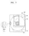
- Figure 7 shows a disc cartridge 200 having a centering spring 230 according to another preferred embodiment of the present invention.
- a plurality of recesses 250 are formed in an inner wall 204 to be spaced a predetermined gap apart from the disc D accommodated in the disc cartridge 200.
- a cantilever centering spring 230 is provided in each of the recesses 250.
- the centering sprig 230 includes a contact portion 232 contacting the disc D and an elastic portion 234 having one side portion supported at the recess 250 and elastically deformed.
- the centering spring 230 is preferably formed integrally with the inner wall 204 and the recess 250 by a one-time injection process.
- the gap d between the disc D and the inner wall 204 is a sum of the gap d1 between the outer circumference of the disc D and the contact portion 232 and a gap d2 between a surface of the contact portion 232 and the inner wall 104.
- the disc cartridge 200 having the centering spring 230 of the above cantilever structure maintains a state in which the disc D loaded in the disc drive is primarily centered as in the previous preferred embodiment.
- the pressure by the disc D is transferred to the contact portion 232 and accordingly the elastic portion 234 deformed inwardly the recess 250 provides allowance in gap to the opposite side.
- a gap in which a disc moves in the disc cartridge is restricted so that the length in which the disc clamp contacts the disc clamp guide can be reduced.
- the height of the disc clamp is reduced so that the thickness of the cartridge is reduced and miniaturization of the disc cartridge is possible.
Abstract
Description
- The present invention relates to a disc cartridge, and more particularly, to a disc cartridge having a means for centering a disc accommodated in the disc cartridge not to be deviated much from the center of a case.
- Figure 1 is a perspective view showing a cartridge loaded and unloaded in a slot-in manner, in which a shutter is open. Referring to the drawing, a
disc cartridge 1 includes acase 3 forming the outer appearance. A circularinner wall 4 encompassing a space where a disc D is placed is formed in thecase 3. The circularinner wall 4 is spaced a predetermined gap d apart from an edge of the disc D. - The
case 3 includes anupper case 3a and alower case 3b. In thelower case 3b of thecase 3, a clamping area D3 where a clamp 8 (see Figure 2B) of the disc D and anopen portion 7 corresponding to a read/write area D4 of the disc D are formed. The clamping area D3 and theopen portion 7 are opened and shut by ashutter 5 guided by ashutter guide 6. - Figure 2A is a sectional view taken along line II-II' of Figure 1, in which the disc D is placed on a
spindle hub 14. Figure 2B is an enlarged sectional view of an oval portion referenced by a in Figure 2A. Referring to the drawings, adisc clamp 8 which has a donut shape having a through hole at the center thereof is provided at the central portion of the disc D. Aconvex portion 9 where aninclined portion 9a is formed along the edge thereof is formed around a through hole at the bottom surface of thedisc clamp 8. - The
disc clamp 8 is placed on thespindle hub 14. Thespindle hub 14 includes aguide portion 12 inclined corresponding to theconvex portion 9 of thedisc clamp 8 and apermanent magnet 13 for generating a clamping force with respect to thedisc clamp 8. Aspindle hub shaft 10 having a protrudingportion 10a for centering the disc D with respect to thespindle hub 14 by entering the through hole of thedisc clamp 8 of the disc D, is formed at the central portion of thespindle hub 14. - The loading and unloading operation of the
disc cartridge 1 having the above structure with respect to a slot-in type disc drive (not shown) is described in detail with reference to the drawings as follows. - When the
disc cartridge 1 is pushed into the disc drive, theshutter 5 is moved to one side along theshutter guide 6 to open theopen portion 7 so that an optical pickup (not shown) can access the read/write area D4 of the disc D. Here, thecase 3 is firmly held by a loading/unloading apparatus (not shown) of the disc drive. When theinclined portion 9a of thedisc clamp 8 is positioned within a corresponding inclined area of theguide portion 12, the disc D slides along an inclined surface of theguide portion 12 so that thedisc clamp 8 and thespindle hub 14 are engaged with each other. Thus, thedisc clamp 8 is accommodated on thespindle hub shaft 10 and firmly held by being clamped by a magnetic force of thepermanent magnet 13. - When the
disc cartridge 1 is unloaded from the disc drive, thedisc cartridge 1 is pressed in a direction indicated by an arrow A in Figure 1 in which thedisc cartridge 1 enters in the disc drive. Here, only thecase 3 moved in the direction A in a state in which the disc D is firmly held on thespindle hub 14. Next, an unloading system (not shown) of the disc drive pushes thecartridge 1 in a direction opposite to the direction A of Figure 1. Accordingly, a portion of thelower case 3b of thedisc cartridge 1 to be adjacent to thedisc clamp 8 is inserted between thedisc clamp 8 and thespindle hub 14 to separate thedisc clamp 8 from theguide portion 12. Theseparated disc cartridge 1 is unloaded from the disc drive and theshutter 5 is shut. - Thus, when the
disc cartridge 1 having the above structure is unloaded, a gap in which thecase 3 can move in a state in which the disc D is firmly held by a magnetic force on thespindle hub 14, is needed. That is, the gap between the outer circumference of the disc D and theinner wall 4 should be greater than a gap required for rotation of the disc D by a spindle motor (not shown). The disc D to be loaded moves within the above gap inside thecase 3. When the disc D moved to one side in thedisc cartridge 1 is to be accommodated on thespindle hub 14, since theinclined portion 9a of thedisc clamp 8 must be designed to be positioned within an inclined area of theguide portion 12 corresponding to theinclined portion 9a, the width of theinclined portion 9a increases in proportional to the gap between the outer circumference of the disc D and theinner wall 4. Accordingly, the height of theconvex portion 9 and the thickness of thedisc cartridge 1 increase so that miniaturization of thedisc cartridge 1 is prevented. - It is an aim of the present invention to provide a disc cartridge which helps to provide a gap between a disc and the case of the disc cartridge when the disc cartridge is unloaded from a slot-in type disc drive. Also, ideally it is desired to centre the disk within a predetermined range when the disc is loaded in the disc drive.
- According to the present invention there is provided a disc cartridge including a disc which is an information recording medium and a case for accommodating the disc, in which the disc includes at least one centering spring for preventing deviation of the disc, which is provided with a predetermined gap outwardly from the outer circumference of the disc in the case.
- It is preferred in the present invention that four centering springs are provided.
- It is preferred in the present invention that the centering spring comprises a contact portion disposed to face the disc and receiving a pressing force by being in contact with the disc, and an elastic portion extending from the contact portion and fixed by the case, and elastically deformed in a direction opposite to a direction in which pressure is applied to the contact portion by the disc.
- It is preferred in the present invention that the contact portion protrudes from an inner wall for forming a space for accommodating the disc to be spaced a predetermined gap from the outer circumference of the disc, that the elastic portion is formed at both sides of the contact portion, and that the elastic portion is formed at one side of the contact portion.
- It is preferred in the present invention that the centering spring is formed integrally with the case.
- For a better understanding of the invention, and to show how embodiments of the same may be carried into effect, reference will now be made, by way of example, to the accompanying diagrammatic drawings in which:
- Figure 1 is a perspective view showing a cartridge which is loaded and unloaded in a slot-in manner;
- Figure 2A is a sectional view taken along line II-II' of Figure 1;
- Figure 2B is an enlarged sectional view of a portion indicated by a in Figure 2A;
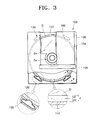
- Figure 3 is a partially cut-away plan view showing a disc cartridge having a centering spring according to a preferred embodiment of the present invention;
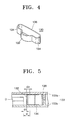
- Figure 4 is a perspective view showing the centering spring of Figure 3;
- Figure 5 is a sectional view taken along line V-V' of Figure 3;
- Figure 6 is a plan view for explaining the operation of the disc cartridge of Figure 3; and
- Figure 7 is a plan view showing a disc cartridge having a centering spring according to another preferred embodiment of the present invention.
-
- In Figures 3, 4, and 5, the same elements having the same functions as those in the above-described conventional invention are indicated by the same reference numerals and descriptions thereof will be omitted.
- Referring to the drawings, a
disc cartridge 100 includes acase 103 forming the outer appearance. Aninner wall 104 which defines a space for accommodating the disc D, is formed in thecase 103. Thecase 103 is divided into anupper case 103a and alower case 103b, as shown in Figure 5. The clamping area D3 and anopen portion 107 for accessing the read/write area D4 are formed on thelower case 103a. Ashutter 105 for opening and shutting theopen portion 107 and ashutter guide 106 for guiding theshutter 105 are provided. - The
inner wall 104 is formed with a predetermined gap d from the outer circumference of the disc D. A plurality ofrecesses 120 are formed in parts of theinner wall 104. A disc biasing element such as acenter spring 130 which contacts the outer circumference of the disc D and restricts the position of the disc D, is provided in each of therecesses 120. The centering springdisc liasing element 120 includes acontact portion 132 contacting the disc D, asupport portion 136 extending from thecontact portion 132 and fixed by theinner wall 104 and the inside of thecase 103, and anelastic portion 134 elastically deformed by a pressing force of the disc D in a direction of pressure (in the opposite direction to a direction indicated by an arrow B in Figure 6). Thesupport portion 136 may be formed integrally with theinner wall 104 and thecase 103. - The gap d between the disc D and the
inner wall 104 is a sum of a gap d1 between the outer circumference of the disc D and thecontact portion 132 and a gap d2 between thecontact portion 132 and theinner wall 104, as shown inEquation 1. - The gap d1 is allowance in gap needed when the disc D rotates within the
cartridge 100. The gap d2 is a gap for securing the gap between the disc D and theinner wall 104 in the state in which the disc D is firmly held on thespindle hub 14 when thedisc cartridge 100 is unloaded from the disc drive by being pushed in a direction indicated by an arrow B in Figure 6. - The loading and unloading operation of the
disc cartridge 100 having the centeringspring 130 of the above structure with respect to a slot-in type disc drive is described below in detail with reference to the attached drawings. Here, the spindle hub and the disc clamp in this preferred embodiment have the same structures and functions as those shown in Figures 2A and 2B while having different size thereof. - When the
disc cartridge 100 is pushed into the disc drive, theshutter 105 moves to one side along theshutter guide 106 to open theopen portion 107 so that an optical pickup (not shown) accesses the read/write area D4 of the disc D. Here, thecartridge case 103 is firmly held by a loading/unloading apparatus (not shown) of the disc drive. When theinclined portion 9a of thedisc clamp 8 is positioned within a range of an inclination area of thecorresponding guide portion 12, the disc D primarily centered within the gap d1 by the centeringspring 130 slides along the inclination area of theguide portion 12. Thedisc clamp 8 and thespindle hub 14 are engaged and clamped with each other by a magnetic force of themagnet 13. - To unload the
disc cartridge 100 from the disc drive, thedisc cartridge 100 is pushed in the direction B in which thedisc cartridge 100 enters the disc drive. Thedisc cartridge 100 in which the disc D is firmly held on thespindle hub 14 enters in the direction B. Accordingly, as shown in Figure 6, thecontact portion 132 of the centeringspring 130 disposed at a tail portion of thedisc cartridge 100 with respect to the direction B is pressed by the disc D, so that theelastic portion 134 is elastically deformed by the gap d2 outward therecess 120. Thus, the allowance in distance between the outer circumference of the disc D and theinner wall 104 is secured as in the state in which the centeringspring 130 does not exist. Next, an unloading system (not shown) of the disc drive pushes thedisc cartridge 100 in a direction in which thedisc cartridge 100 is unloaded, that is, in the direction opposite to the direction B of Figure 6. Accordingly, a portion of thelower case 103b of thedisc cartridge 100 which is adjacent to thedisc clamp 8 is inserted between thedisc clamp 8 and thespindle hub 14 to separate thedisc clamp 8 from theguide portion 12. The separatedcartridge 100 is unloaded from the disc drive and subsequently theshutter 104 is shut. The elastically deformedelastic portion 134 restores the original state. - Figure 7 shows a
disc cartridge 200 having a centeringspring 230 according to another preferred embodiment of the present invention. A plurality ofrecesses 250 are formed in aninner wall 204 to be spaced a predetermined gap apart from the disc D accommodated in thedisc cartridge 200. Acantilever centering spring 230 is provided in each of therecesses 250. The centeringsprig 230 includes acontact portion 232 contacting the disc D and anelastic portion 234 having one side portion supported at therecess 250 and elastically deformed. The centeringspring 230 is preferably formed integrally with theinner wall 204 and therecess 250 by a one-time injection process. The gap d between the disc D and theinner wall 204 is a sum of the gap d1 between the outer circumference of the disc D and thecontact portion 232 and a gap d2 between a surface of thecontact portion 232 and theinner wall 104. - The
disc cartridge 200 having the centeringspring 230 of the above cantilever structure maintains a state in which the disc D loaded in the disc drive is primarily centered as in the previous preferred embodiment. When thedisc cartridge 200 is unloaded from the disc drive, the pressure by the disc D is transferred to thecontact portion 232 and accordingly theelastic portion 234 deformed inwardly therecess 250 provides allowance in gap to the opposite side. - As described above, in the disc cartridge according to the present invention, a gap in which a disc moves in the disc cartridge is restricted so that the length in which the disc clamp contacts the disc clamp guide can be reduced. Thus, the height of the disc clamp is reduced so that the thickness of the cartridge is reduced and miniaturization of the disc cartridge is possible.
- While this invention has been particularly shown and described with reference to preferred embodiments thereof, it will be understood by those skilled in the art that various changes in form and details may be made therein without departing from the scope of the invention as defined by the appended claims.
- The reader's attention is directed to all papers and documents which are filed concurrently with or previous to this specification in connection with this application and which are open to public inspection with this specification, and the contents of all such papers and documents are incorporated herein by reference.
- All of the features disclosed in this specification (including any accompanying claims, abstract and drawings), and/or all of the steps of any method or process so disclosed, may be combined in any combination, except combinations where at least some of such features and/or steps are mutually exclusive.
- Each feature disclosed in this specification (including any accompanying claims, abstract and drawings), may be replaced by alternative features serving the same, equivalent or similar purpose, unless expressly stated otherwise. Thus, unless expressly stated otherwise, each feature disclosed is one example only of a generic series of equivalent or similar features.
- The invention is not restricted to the details of the foregoing embodiment(s) . The invention extends to any novel one, or any novel combination, of the features disclosed in this specification (including any accompanying claims, abstract and drawings), or to any novel one, or any novel combination, of the steps of any method or process so disclosed.
Claims (7)
- A disc cartridge (100) including a disc (D) which is an information recording medium and a case (103) for accommodating the disc, characterized by comprising at least one centering spring (130) for preventing deviation of the disc, which is provided with a predetermined gap (d2) outwardly from the outer circumference of the disc in the case.
- The disc cartridge (100) as claimed in claim 1, wherein four centering springs (130) are provided.
- The disc cartridge as claimed in claim 1 or 2, wherein the or each centering spring comprises:a contact portion (132) disposed to face the disc and receiving a pressing force by being in contact with the disc; andan elastic portion (134) extending from the contact portion and fixed by the case, and elastically deformed in a direction opposite to a direction in which pressure is applied to the contact portion by the disc.
- The disc cartridge as claimed in claim 3, wherein the contact portion (132) protrudes from an inner wall (104) for forming a space for accommodating the disc to be spaced a predetermined gap from the outer circumference of the disc.
- The disc cartridge as claimed in claim 3 or 4, wherein the elastic portion (134) is formed at both sides of the contact portion (132).
- The disc cartridge as claimed in claim 3 or 4, wherein the elastic portion (134) is formed at one side of the contact portion (132).
- The disc cartridge as claimed in any preceding claim, wherein the centering spring (130) is formed integrally with the case (103).
Applications Claiming Priority (2)
| Application Number | Priority Date | Filing Date | Title |
|---|---|---|---|
| KR2001033529 | 2001-06-14 | ||
| KR1020010033529A KR100750102B1 (en) | 2001-06-14 | 2001-06-14 | Disk Cartridge |
Publications (3)
| Publication Number | Publication Date |
|---|---|
| EP1267351A2 true EP1267351A2 (en) | 2002-12-18 |
| EP1267351A3 EP1267351A3 (en) | 2006-02-08 |
| EP1267351B1 EP1267351B1 (en) | 2007-05-30 |
Family
ID=19710833
Family Applications (1)
| Application Number | Title | Priority Date | Filing Date |
|---|---|---|---|
| EP02252207A Expired - Fee Related EP1267351B1 (en) | 2001-06-14 | 2002-03-27 | Disc cartridge |
Country Status (6)
| Country | Link |
|---|---|
| US (1) | US6940806B2 (en) |
| EP (1) | EP1267351B1 (en) |
| JP (1) | JP3488226B2 (en) |
| KR (1) | KR100750102B1 (en) |
| CN (1) | CN100399466C (en) |
| DE (1) | DE60220340T2 (en) |
Families Citing this family (3)
| Publication number | Priority date | Publication date | Assignee | Title |
|---|---|---|---|---|
| CN100524495C (en) * | 2004-03-08 | 2009-08-05 | 松下电器产业株式会社 | Case member and cartridge |
| JP4224424B2 (en) * | 2004-05-10 | 2009-02-12 | 株式会社ソニー・コンピュータエンタテインメント | Disk unit |
| JP4369294B2 (en) * | 2004-05-13 | 2009-11-18 | 株式会社エヌ・ティ・ティ・ドコモ | Noise power estimation apparatus, noise power estimation method, and signal detection apparatus |
Citations (3)
| Publication number | Priority date | Publication date | Assignee | Title |
|---|---|---|---|---|
| US4802049A (en) * | 1986-02-10 | 1989-01-31 | Tdk Corporation | Disc cartridge |
| JPH0773633A (en) * | 1993-09-01 | 1995-03-17 | Nec Gumma Ltd | Optical disk cartridge |
| US5499233A (en) * | 1994-06-20 | 1996-03-12 | International Business Machines Corporation | Optical disk carrier with write-protect mechanism |
Family Cites Families (12)
| Publication number | Priority date | Publication date | Assignee | Title |
|---|---|---|---|---|
| JPS6085479A (en) * | 1983-10-14 | 1985-05-14 | Hitachi Maxell Ltd | Disk cartridge |
| JPS6168782A (en) * | 1984-09-12 | 1986-04-09 | Sony Corp | Disc cartridge |
| US4863031A (en) * | 1985-12-18 | 1989-09-05 | Tdk Corporation | Disc cartridge having peripheral disc support |
| CA1297631C (en) | 1985-12-23 | 1992-03-17 | Sesha I. Natarajan | Ureido renin inhibitors |
| JPH0447805Y2 (en) * | 1987-09-24 | 1992-11-11 | ||
| CN2107164U (en) | 1991-09-24 | 1992-06-17 | 余晓宁 | Weather-umbrella for bicycling and walking |
| JP3426810B2 (en) * | 1995-10-13 | 2003-07-14 | 株式会社東芝 | Disk cartridge device and its display label |
| JPH09245454A (en) * | 1996-03-05 | 1997-09-19 | Sony Corp | Disk cartridge |
| JPH09259562A (en) * | 1996-03-19 | 1997-10-03 | Sony Corp | Disc cartridge |
| US5898664A (en) * | 1996-03-19 | 1999-04-27 | Sony Corporation | Position controlling mechanism for a disc cartridge |
| CA2367481A1 (en) | 1999-04-22 | 2000-11-02 | Ursula Luckow | Device for holding disk-shaped storage elements |
| DE19918275A1 (en) | 1999-04-22 | 2000-11-02 | Ursula Luckow | Device for receiving disc-shaped information carriers |
-
2001
- 2001-06-14 KR KR1020010033529A patent/KR100750102B1/en not_active IP Right Cessation
-
2002
- 2002-03-12 CN CNB021071640A patent/CN100399466C/en not_active Expired - Fee Related
- 2002-03-18 JP JP2002074747A patent/JP3488226B2/en not_active Expired - Fee Related
- 2002-03-27 DE DE60220340T patent/DE60220340T2/en not_active Expired - Fee Related
- 2002-03-27 EP EP02252207A patent/EP1267351B1/en not_active Expired - Fee Related
- 2002-04-29 US US10/133,903 patent/US6940806B2/en not_active Expired - Fee Related
Patent Citations (3)
| Publication number | Priority date | Publication date | Assignee | Title |
|---|---|---|---|---|
| US4802049A (en) * | 1986-02-10 | 1989-01-31 | Tdk Corporation | Disc cartridge |
| JPH0773633A (en) * | 1993-09-01 | 1995-03-17 | Nec Gumma Ltd | Optical disk cartridge |
| US5499233A (en) * | 1994-06-20 | 1996-03-12 | International Business Machines Corporation | Optical disk carrier with write-protect mechanism |
Non-Patent Citations (1)
| Title |
|---|
| PATENT ABSTRACTS OF JAPAN vol. 1995, no. 06, 31 July 1995 (1995-07-31) -& JP 07 073633 A (NEC GUMMA LTD), 17 March 1995 (1995-03-17) * |
Also Published As
| Publication number | Publication date |
|---|---|
| EP1267351B1 (en) | 2007-05-30 |
| CN1392560A (en) | 2003-01-22 |
| US20020191532A1 (en) | 2002-12-19 |
| KR20020095339A (en) | 2002-12-26 |
| DE60220340T2 (en) | 2008-01-31 |
| DE60220340D1 (en) | 2007-07-12 |
| JP2003007022A (en) | 2003-01-10 |
| EP1267351A3 (en) | 2006-02-08 |
| US6940806B2 (en) | 2005-09-06 |
| JP3488226B2 (en) | 2004-01-19 |
| KR100750102B1 (en) | 2007-08-17 |
| CN100399466C (en) | 2008-07-02 |
Similar Documents
| Publication | Publication Date | Title |
|---|---|---|
| EP0553034B1 (en) | Disc table for disc recording/reproducing - apparatus | |
| CA1324212C (en) | Disk cartridge with hub seal | |
| JP4113522B2 (en) | Recording disk driving motor and recording disk driving apparatus using the recording disk driving motor | |
| KR20040086501A (en) | Disc cartridge | |
| EP1267351A2 (en) | Disc cartridge | |
| JP2001229638A (en) | Disk cartridge and disk drive assembly | |
| EP1286453B1 (en) | Disk apparatus capable of automatically adjusting balance at the time of disk rotation | |
| KR100406657B1 (en) | Disk cartridge and disk driver | |
| US20060195855A1 (en) | Cartridge type recording medium and disk-shaped recording medium including a hole for centering each thereof, cartridge, driving unit and driving method | |
| EP1659587B1 (en) | Disk cartridge | |
| US6243231B1 (en) | Disk cartridge with anti-rattle mechanism | |
| EP1304699A2 (en) | Disk cartridge | |
| EP1659585B1 (en) | Disk cartridge | |
| CN101681659A (en) | Disk cartridge | |
| KR100585134B1 (en) | Apparatus for holding disk and disk tray provided with the same | |
| US5680284A (en) | Center core and shutter for a high density magnetic disk cartridge | |
| JP4538374B2 (en) | Disk unit | |
| KR100739668B1 (en) | A clamping apparatus for disk drive | |
| KR0140883B1 (en) | Center core of magnetic disk | |
| US6259582B1 (en) | Chucking device in FDD | |
| KR20000068722A (en) | Disc cartridge | |
| KR20050042083A (en) | Disc cartridge | |
| JP2002203349A (en) | Disk table and recording and/or reproducing device | |
| JP3512029B2 (en) | Disc table and recording and / or reproducing apparatus | |
| JPH04216364A (en) | Disk loader |
Legal Events
| Date | Code | Title | Description |
|---|---|---|---|
| PUAI | Public reference made under article 153(3) epc to a published international application that has entered the european phase |
Free format text: ORIGINAL CODE: 0009012 |
|
| 17P | Request for examination filed |
Effective date: 20020416 |
|
| AK | Designated contracting states |
Kind code of ref document: A2 Designated state(s): AT BE CH CY DE DK ES FI FR GB GR IE IT LI LU MC NL PT SE TR |
|
| AX | Request for extension of the european patent |
Free format text: AL;LT;LV;MK;RO;SI |
|
| PUAL | Search report despatched |
Free format text: ORIGINAL CODE: 0009013 |
|
| AK | Designated contracting states |
Kind code of ref document: A3 Designated state(s): AT BE CH CY DE DK ES FI FR GB GR IE IT LI LU MC NL PT SE TR |
|
| AX | Request for extension of the european patent |
Extension state: AL LT LV MK RO SI |
|
| AKX | Designation fees paid |
Designated state(s): DE FR GB NL |
|
| GRAP | Despatch of communication of intention to grant a patent |
Free format text: ORIGINAL CODE: EPIDOSNIGR1 |
|
| GRAS | Grant fee paid |
Free format text: ORIGINAL CODE: EPIDOSNIGR3 |
|
| GRAA | (expected) grant |
Free format text: ORIGINAL CODE: 0009210 |
|
| AK | Designated contracting states |
Kind code of ref document: B1 Designated state(s): DE FR GB NL |
|
| REG | Reference to a national code |
Ref country code: GB Ref legal event code: FG4D |
|
| REF | Corresponds to: |
Ref document number: 60220340 Country of ref document: DE Date of ref document: 20070712 Kind code of ref document: P |
|
| ET | Fr: translation filed | ||
| PLBE | No opposition filed within time limit |
Free format text: ORIGINAL CODE: 0009261 |
|
| STAA | Information on the status of an ep patent application or granted ep patent |
Free format text: STATUS: NO OPPOSITION FILED WITHIN TIME LIMIT |
|
| 26N | No opposition filed |
Effective date: 20080303 |
|
| PGFP | Annual fee paid to national office [announced via postgrant information from national office to epo] |
Ref country code: NL Payment date: 20080303 Year of fee payment: 7 |
|
| PGFP | Annual fee paid to national office [announced via postgrant information from national office to epo] |
Ref country code: DE Payment date: 20080407 Year of fee payment: 7 Ref country code: FR Payment date: 20080311 Year of fee payment: 7 |
|
| PGFP | Annual fee paid to national office [announced via postgrant information from national office to epo] |
Ref country code: GB Payment date: 20080402 Year of fee payment: 7 |
|
| GBPC | Gb: european patent ceased through non-payment of renewal fee |
Effective date: 20090327 |
|
| NLV4 | Nl: lapsed or anulled due to non-payment of the annual fee |
Effective date: 20091001 |
|
| REG | Reference to a national code |
Ref country code: FR Ref legal event code: ST Effective date: 20091130 |
|
| PG25 | Lapsed in a contracting state [announced via postgrant information from national office to epo] |
Ref country code: DE Free format text: LAPSE BECAUSE OF NON-PAYMENT OF DUE FEES Effective date: 20091001 |
|
| PG25 | Lapsed in a contracting state [announced via postgrant information from national office to epo] |
Ref country code: NL Free format text: LAPSE BECAUSE OF NON-PAYMENT OF DUE FEES Effective date: 20091001 |
|
| PG25 | Lapsed in a contracting state [announced via postgrant information from national office to epo] |
Ref country code: GB Free format text: LAPSE BECAUSE OF NON-PAYMENT OF DUE FEES Effective date: 20090327 Ref country code: FR Free format text: LAPSE BECAUSE OF NON-PAYMENT OF DUE FEES Effective date: 20091123 |