EP1267302A2 - Media width detecting system for an imaging apparatus - Google Patents
Media width detecting system for an imaging apparatus Download PDFInfo
- Publication number
- EP1267302A2 EP1267302A2 EP02076886A EP02076886A EP1267302A2 EP 1267302 A2 EP1267302 A2 EP 1267302A2 EP 02076886 A EP02076886 A EP 02076886A EP 02076886 A EP02076886 A EP 02076886A EP 1267302 A2 EP1267302 A2 EP 1267302A2
- Authority
- EP
- European Patent Office
- Prior art keywords
- media
- measuring pattern
- width
- reader
- pattern
- Prior art date
- Legal status (The legal status is an assumption and is not a legal conclusion. Google has not performed a legal analysis and makes no representation as to the accuracy of the status listed.)
- Withdrawn
Links
Images



Classifications
-
- G—PHYSICS
- G01—MEASURING; TESTING
- G01B—MEASURING LENGTH, THICKNESS OR SIMILAR LINEAR DIMENSIONS; MEASURING ANGLES; MEASURING AREAS; MEASURING IRREGULARITIES OF SURFACES OR CONTOURS
- G01B11/00—Measuring arrangements characterised by the use of optical techniques
- G01B11/02—Measuring arrangements characterised by the use of optical techniques for measuring length, width or thickness
- G01B11/04—Measuring arrangements characterised by the use of optical techniques for measuring length, width or thickness specially adapted for measuring length or width of objects while moving
- G01B11/046—Measuring arrangements characterised by the use of optical techniques for measuring length, width or thickness specially adapted for measuring length or width of objects while moving for measuring width
-
- B—PERFORMING OPERATIONS; TRANSPORTING
- B41—PRINTING; LINING MACHINES; TYPEWRITERS; STAMPS
- B41J—TYPEWRITERS; SELECTIVE PRINTING MECHANISMS, i.e. MECHANISMS PRINTING OTHERWISE THAN FROM A FORME; CORRECTION OF TYPOGRAPHICAL ERRORS
- B41J11/00—Devices or arrangements of selective printing mechanisms, e.g. ink-jet printers or thermal printers, for supporting or handling copy material in sheet or web form
- B41J11/0025—Handling copy materials differing in width
- B41J11/003—Paper-size detection, i.e. automatic detection of the length and/or width of copy material
-
- B—PERFORMING OPERATIONS; TRANSPORTING
- B65—CONVEYING; PACKING; STORING; HANDLING THIN OR FILAMENTARY MATERIAL
- B65H—HANDLING THIN OR FILAMENTARY MATERIAL, e.g. SHEETS, WEBS, CABLES
- B65H43/00—Use of control, checking, or safety devices, e.g. automatic devices comprising an element for sensing a variable
- B65H43/08—Photoelectric devices
-
- B—PERFORMING OPERATIONS; TRANSPORTING
- B65—CONVEYING; PACKING; STORING; HANDLING THIN OR FILAMENTARY MATERIAL
- B65H—HANDLING THIN OR FILAMENTARY MATERIAL, e.g. SHEETS, WEBS, CABLES
- B65H2511/00—Dimensions; Position; Numbers; Identification; Occurrences
- B65H2511/10—Size; Dimensions
- B65H2511/12—Width
-
- B—PERFORMING OPERATIONS; TRANSPORTING
- B65—CONVEYING; PACKING; STORING; HANDLING THIN OR FILAMENTARY MATERIAL
- B65H—HANDLING THIN OR FILAMENTARY MATERIAL, e.g. SHEETS, WEBS, CABLES
- B65H2553/00—Sensing or detecting means
- B65H2553/40—Sensing or detecting means using optical, e.g. photographic, elements
- B65H2553/43—Bar code reader
-
- B—PERFORMING OPERATIONS; TRANSPORTING
- B65—CONVEYING; PACKING; STORING; HANDLING THIN OR FILAMENTARY MATERIAL
- B65H—HANDLING THIN OR FILAMENTARY MATERIAL, e.g. SHEETS, WEBS, CABLES
- B65H2557/00—Means for control not provided for in groups B65H2551/00 - B65H2555/00
- B65H2557/20—Calculating means; Controlling methods
-
- G—PHYSICS
- G03—PHOTOGRAPHY; CINEMATOGRAPHY; ANALOGOUS TECHNIQUES USING WAVES OTHER THAN OPTICAL WAVES; ELECTROGRAPHY; HOLOGRAPHY
- G03G—ELECTROGRAPHY; ELECTROPHOTOGRAPHY; MAGNETOGRAPHY
- G03G2215/00—Apparatus for electrophotographic processes
- G03G2215/00362—Apparatus for electrophotographic processes relating to the copy medium handling
- G03G2215/00535—Stable handling of copy medium
- G03G2215/00611—Detector details, e.g. optical detector
- G03G2215/00616—Optical detector
-
- G—PHYSICS
- G03—PHOTOGRAPHY; CINEMATOGRAPHY; ANALOGOUS TECHNIQUES USING WAVES OTHER THAN OPTICAL WAVES; ELECTROGRAPHY; HOLOGRAPHY
- G03G—ELECTROGRAPHY; ELECTROPHOTOGRAPHY; MAGNETOGRAPHY
- G03G2215/00—Apparatus for electrophotographic processes
- G03G2215/00362—Apparatus for electrophotographic processes relating to the copy medium handling
- G03G2215/00535—Stable handling of copy medium
- G03G2215/00717—Detection of physical properties
- G03G2215/00734—Detection of physical properties of sheet size
Definitions
- the present invention relates to a system and method for measuring and/or detecting the width of media, such as photosensitive paper, and an imaging apparatus such as a photographic printer which uses the media width detecting system.
- photographic printers are capable of utilizing multiple paper widths.
- these printers do not provide for a convenient and accurate system for communicating the paper width to the printer as new unexposed rolls of paper are placed into the printer.
- Some printers rely on a person that operates the machine to input the paper width manually, either via a computer interface or setting switches or dials.
- Other printers utilize switches or magnets that are part of an input paper cassette magazine where the switches are set by the person operating the printer.
- an array of discrete sensors often photo-optic, can be used to directly measure the width of paper without operator intervention.
- the sensors are physically placed on the paper track such that they detect the popular widths of photosensitive paper.
- one edge of the paper being measured is required to be geometrically known. In other words, one paper edge must be located against a guide of known location from the sensor array. Without this reference edge, the true paper width cannot be accurately measured.
- the present invention provides for an improved system and method for measuring an absolute width of media, such as paper photosensitive film, photographic paper, cut sheets, a web, etc., without the need for human intervention and/or without the need for the paper to be referenced against a known location or guide.
- an absolute width of media such as paper photosensitive film, photographic paper, cut sheets, a web, etc.
- the paper and any location in a paper tracking mechanism is measured from one edge to the other.
- the present invention provides for an accurate and simple mechanism that detects both edges and the span therebetween.
- a media width detecting system uses a measuring pattern which, for example, can be a plurality of bars placed across the width of the paper track.
- the bars can be either permanently placed or be in the form of a sticker or label placed across the width of the paper track.
- the bars can be spaced at known intervals or can be at variable intervals depending on the method of measuring.
- media such as photosensitive paper is placed in the paper track
- a subset of the bars are physically covered up or blocked.
- the number of uncovered and covered bars can be easily computed. From this, the paper width can then be determined.
- the present invention provides for a media width detecting system that comprises a measuring pattern provided across a width of a media path; a reader positioned to view a full width of the measuring pattern, wherein media in the media path that traverses the measuring pattern blocks or covers up a portion of the measuring pattern from being viewed by the reader and leaves other portions of the measuring pattern exposed for viewing by the reader; and a computing device operationally associated with the reader that determines a width of the media traversing the measuring pattern based on a difference between the full width of the measuring pattern and a width of the other portions of the measuring pattern left exposed for viewing by the reader when the media traverses the measuring pattern.
- the description with respect to the computing device being operationally associated with the reader refers to the fact that the present invention can provide for a computing device separate from the reader and integrated into the hardware of the imaging apparatus that is processing the media, a computing device separate from both the reader and imaging apparatus and connected to both, or a computing device integrated into the reader.
- the present invention further provides for a media width detecting system that comprises a bar code pattern including a predetermined number X of total bars provided at intervals on a media path so as to extend along a width of the media path; a reader provided relative to the media path so as to view an entire width of the bar code pattern, wherein the media in the media path that traverses the bar code pattern provides for a first number N of uncovered bars on one side or both sides of the media that can be read by the reader; and a computing device operationally associated with the reader that computes a second number W of bars covered by the media traversing the bar code pattern based on a difference between the predetermined number X of total bars and the first number N of uncovered bars to determine a width of the media transversing the bar code pattern.
- a media width detecting system that comprises a bar code pattern including a predetermined number X of total bars provided at intervals on a media path so as to extend along a width of the media path; a reader provided relative to the media path so as to view an
- the present invention further relates to a media width detecting system that comprises a measuring pattern; a reader positioned to view the measuring pattern, wherein media that traverses the measuring pattern blocks a portion of the measuring pattern from being viewed by the reader; and a computing device operationally associated with the reader that determines a width of the media traversing the measuring pattern based on at least a width of the portion of the measuring pattern blocked by the media traversing the measuring pattern.
- the present invention further relates to a media size detecting system that comprises a first measuring pattern provided across a width of a media path; a second measuring pattern provided on the media path so as to extend along a longitudinal direction of the media path; and a reader adapted to read the first measuring pattern to determine a width of media traversing the first measuring pattern, and read the second measuring pattern to determine a length of media traversing the second measuring pattern.
- the present invention further relates to a method of measuring a size of media being conveyed along a media path which comprises providing a first measuring pattern across a width of the media path; positioning a reader relative to the media path so as to view a full width of the first measuring pattern; and determining a width of media in the media path which traverses the first measuring pattern based on at least a width of a portion of the first measuring pattern which is blocked from being viewed by the reader by the media traversing the first measuring pattern.
- the present invention further relates to a printing apparatus that comprises a media supply section having at least one media entry opening for the passage of media therethrough; a printing section adapted to accept media from the media supply section; a media path for the passage of media from the media supply section to the printing section; and a media width detecting system positioned on the media path.
- the media width detecting system comprises a measuring pattern provided across a width of a media path; a reader positioned relative to the media path to view the measuring pattern, wherein media in the media path that traverses the measuring pattern blocks a portion of the measuring pattern from being viewed by the reader; and a computing device operationally associated with the reader that determines a width of the media traversing the measuring pattern based on at least a width of the portion of the measuring pattern blocked by the media traversing the measuring pattern.
- the present invention further relates to a printing apparatus that comprises a media supply section that has at least one media entry opening for the passage of media therethrough; at least one media supply cassette having a media supply roll therein and positioned at the at least one media entry opening to supply media to the media supply section; a printing section adapted to accept media from the media supply section; and a media width detecting system positioned at an exit of the at least one media supply cassette.
- the media width detecting system comprises a measuring pattern positioned on a media path at the exit; a reader positioned to view the measuring pattern, wherein media which traverses the measuring pattern blocks a portion of the measuring pattern from being viewed by the reader; and a computing device operationally associated with the reader that determines a width of the media traversing the measuring pattern based on at least a width of the portion of the measuring pattern blocked by the media traversing the measuring pattern.
- the present invention further relates to a media width detecting system that comprises a measuring pattern; and a reader positioned to view the measuring pattern, wherein media that traverses the measuring pattern blocks a portion of the measuring pattern from being viewed by the reader, and a width of the media traversing the measuring pattern is determined based on at least a width of the portion of the measuring pattern blocked by the media traversing the measuring pattern.
- the present invention further relates to a printing apparatus that comprises a media supply section having at least one media entry opening for the passage of media therethrough; a printing section adapted to accept media from the media supply section; a media path for the passage of media from the media supply section to the printing section; and a media width detecting system positioned on the media path.
- the media width detecting system comprises a measuring pattern provided across a width of the media path; and a reader positioned relative to the media path to view the measuring pattern, wherein media in the media path that traverses the measuring path blocks a portion of the measuring pattern from being viewed by the reader, and a width of the media traversing the measuring pattern is measured based on at least a width of the portion of the measuring pattern blocked by the media traversing the measuring pattern.
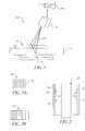
- Fig. 1 illustrates a media width detecting system 100 in accordance with a feature of the present invention.
- a paper track or media path 10 can be located inside an imaging apparatus, such as, for example, a photo printer, at the location where media paper width measurement is desired.
- the present invention is not limited to placing media width detecting system 100 inside an imaging apparatus.
- media width detecting system 100 can be placed at an outlet of a paper cassette which feeds media to the imaging apparatus.
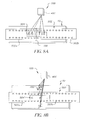
- measuring pattern 22 can be in the form of a barcode pattern or a series of uniform bars 25 (Fig. 2A) that span across a width of media path 10 (Fig. 3). Bars 25 can be alternating reflective/non-reflective (white and black), as noted in Fig. 2, and can be comprised of a fixed and known number of bars X. With the arrangement of the present invention, measuring pattern 22 is spaced across a width of media path 10 such that media 21 which is conveyed along media path 10 will traverse measuring pattern 22 to block a portion of measuring pattern 22.
- Media 21 can be photographic paper, photosensitive film, cut sheets, a web, etc.
- the size or width of the portion of measuring pattern 22 blocked by the media depends on the width of media 21. More specifically, as illustrated in Fig. 3, when media 21 traverses measuring pattern 22, in the example where measuring pattern 22 is in the form of a bar code pattern, a subset of the total bars of the bar code pattern will be covered. The bars which are not covered are identified by reference numerals 30 and 31 in Fig. 3. For example, in the situation of Fig. 3, the total number of bars of measuring pattern or bar code pattern 22 is equal to X.
- the total number of bars 30, 31 which are uncovered or not blocked by media 21 can be equal to N, wherein N equals the total number of uncovered bars 30, 31 on one side and/or either side of media 21.
- a reader 40 such as an optical detection apparatus, a scanner, a sensor or an optical bar code reader is provided relative to media path 10 so as to view media 21 as well as the width of media path 10.
- reader 40 is positioned so as to provide for a swept laser or beam 105 across measuring pattern 22 in media path 10.
- Reader 40 determines by well established methods, the number of bars that are visible on each side of media 21. More specifically, when media 21 traverses measuring pattern 22, a portion of measuring pattern 22, such as for example, a subset of bars 25 will be covered by media 21.
- the uncovered bars (30, 31) (Fig. 3) on each or both sides of media 21 can be read by reader 40. Therefore, in this embodiment, reader 40 can determine via well established methods the number of bars visible on each side of media 21. In the example of Fig. 3, the total number of exposed bars (30 and 31) are equal to N.
- reader 40 can be associated with a computing device 200 which can be separate from reader 40, can be integrated or built into reader 40, or can be part of the associated printer.
- Computing device 200 would already know that the total number of bars across the track equals X.
- computing device 200 would typically be integral to reader 40, and more specifically integral to a commercial bar-code scanner module, often implemented in single-chip microprocessors such as 68 HC11 and 8051 type devices.
- any processor, or computing device having computational features as noted above can be used in the present invention.
- a signal from reader 40 would be an indication of how many bars are exposed and can be read by reader 40, and more specifically how many bars are not blocked by media 21 traversing media path 10. Having this information, the total number of bars or the subset of bars covered by media 21 would be represented by X - N
- the paper or media width can be easily computed by measuring the number of covered or blocked bars.
- the width of bars 25 as well as the spacings can be known, the paper width can be easily determined by knowing the number of bars that are covered. Therefore, in the present invention, by knowing the amount or width of measuring pattern 22, it is possible to determine the width of media 21 that traverses measuring pattern 22. With the system of the present invention, it is not necessary to have paper a paper edge guide or to provide for a starting point for determining the width of the media.
- bars 25 can be spaced at a specific distance so that even if the media is skewed when it traverses the measuring pattern or bar code pattern 22, reader 40 can still determine the width of the media since the number of bars covered would not dramatically change with a skewed media. More specifically, if five bars are covered by media traversing a bar code pattern, the spacing of the bars of the bar code pattern could be such that even if the media is skewed within dimensional tolerances, the five bars would still be covered by the media.
- reader 40 as well as computing device 200 can be programmed to include an error setting in the event that the media arrives at the measuring pattern completely or overly skewed and covers a plurality and/or substantially all of the bars.
- all of the type of media that can be used within the associated imaging apparatus can be accounted for in computing device 200 and/or reader 40, such that, if a substantial number of bars or a number of bars which is not within the stored information in computing device 200 and/or reader 40 is blocked by the skewed media, an error signal can be provided.
- measuring pattern 22 is preferably a bar code pattern having a row of plain bars 25, either with fixed spacing or a fixed number of bars.
- measuring pattern 22 can be a bar code pattern having properly formed bar codes with start and stop sentinels, multiple bar widths, etc., as found in UPC and similar bar codes (see reference number 22' in Fig. 2B).
- measuring pattern 22 can be in the form of multiple properly formed bar codes (for example, bar codes in groups 22') that each represent a displacement measure across the media path.
- measuring pattern 22 can be in the form of a single sticker and/or label 22" for the bar code or painted bars as shown in Fig. 5.
- measuring pattern 22 can be etched/molded into the media path material of media path 10.
- measuring pattern 22 can comprise bars of non-uniform bar widths that each relate to a discrete media width.
- the present invention uses a reader that measures a media width based on covered and uncovered bars of a bar code, it is not affected by the material of the media and thus, can read black or white media as well as gray media.
- reader 40 can be fixed or can be movable or rotatable to multiple locations so as to enable the reading of a media width at the multiple locations. Therefore, you could have a reader 40 that can be rotated or moved so as to read a longitudinally extending bar code pattern, or a second reader dedicated to the longitudinally extending bar code pattern. By having a second reader or a single reader that can be moved or rotated so as to read longitudinally extending bar code patterns, it would possible to also calculate a length of media. Therefore, with this alternative embodiment, reader 40 can be positioned in a first position as illustrated in Fig. 1 so as to measure a width of the media by way of measuring pattern 22. A second reader 40a (Fig.
- reader 40a can further be used as a media encoder, an absolute measure of media positioned lengthwise down the track or to check the position of incoming media.
- a single reader 40b (Fig. 7) that is movable or rotatable between the position shown in Fig. 1 to read widthwise extending measuring pattern 22 (a first measuring pattern), and the position shown in Figs. 6 or 7 to read longitudinally extending measuring pattern 500 (a second measuring pattern) is used.
- the reader can be mounted about a rotatable mount so as to rotate as shown by arrow 1000 in Fig. 7.
- any of readers 40, 40a, 40b and 40c as disclosed in the present specification could be a two dimensional scanner which could read along the longitudinal and horizontal axes without requiring rotatation and/or movement.
- the number of bars which are covered as noted above can be calculated, and the width can be computed and compared to a look-up table.
- reader 40 does not have to be in the form of an optical scanner, and it could read on the basis of light, neutrons, air, etc.
- the present invention is also applicable to measuring the width of other media such as photosensitive film 502 as shown in Fig. 8A.
- the bars of a measuring pattern 700 can be set up as distinct from the splice bar code pattern 504.
- reader 40c would be programmed to distinguish the two patterns.
- reader 40c can be movable or two-dimensional to deal with different orientations.
- Fig 8B illustrates a different arrangement which can be used in the present invention.
- the arrangement of Fig 8B differs from Fig 8A with regard to splice code bar pattern 504.
- splice code bar pattern 504' includes bars which are oriented in the same direction as the bars of measuring pattern 700. That is, the bars of splice code bar pattern 504' are oriented so as to extend in the direction of travel of film 502.
- reader 40c can be programmed to read and/or distinguish measuring pattern 700 from splice code bar pattern 504'.
- a second reader can be used such that one reader can be dedicated to read pattern 700 and the second reader can be dedicated to read pattern 504'.
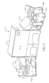
- Fig. 9 shows an example of an imaging apparatus which can use a media width detecting system as disclosed by the present invention.
- the imaging apparatus is in the form of a printing apparatus 150, such as a digital printer, that comprises a media supply section 170 and a media take-up section 190.
- Media supply section 170 is adapted to accommodate a plurality of media supply cassettes 170a, 170b, 170c
- media take-up section 190 is adapted to accommodate a plurality of media take-up cassettes 190a, 190b, 190c.
- supply cassettes 170a-170c can each contain a roll of, for example, media that is to be processed through a printing section 210.
- Take-up cassettes 190a-190c on the take-up side are essentially empty and are adapted to receive a roll of media after it has passed through printing section 210.
- Media width detecting system 100 as illustrated in Fig. 1 can be provided on the media path(s) within supply section 170 such that it would be able to measure the width of media that is supplied from any of cassettes 170a, 170b, 170c.
- the specifics of printing apparatus 150 is described in U.S. Patent 6,227,731 issued May 8, 2001.
- three distinct media width detecting systems 100 can be utilized, with each media detecting system being positioned in a media path that is dedicated to each cassette 170a, 170b, 170c.
- a single reader 40 that is rotatable to each of the media paths dedicated to cassettes 170a, 170b, 170c can be used in supply section 170.
- each of the media paths can include a measuring pattern.
- media width detecting system 100 of the present invention can be associated with each one of the cassettes 170a, 170b, 170c as shown.
- a media with detecting system 100 as disclosed in the present invention would be advantageous in that you would not need an edge guide to measure the width.
- a measuring pattern 350 similar to measuring pattern 22 can be placed below a paper surface at a throat 300 of any of cassettes 170a, 170b, 170c, or any place where the media exits the cassette.
- media width detecting system 100 would be placed at an exit of each cassette 170a, 170b, 170c.
- Reader 40 would be provided relative to measuring pattern 350 to enable a reading of the measuring pattern. Reader 40 can be mounted on cassette 170a, 170b, 170c or some other area of the printer etc. which enables a positioning of the reader as shown.
- reader 40 can scan measuring pattern 350 as previously described and compute the number of bars that are blocked by media 21 traversing measuring pattern 350. Therefore, the width of the media exiting cassette 170a, 170b, 170c would be determined in the same manner as described with reference to Fig. 1.
- a single reader that is movable to a location over the measuring pattern at each cassette throat can be used.
- this system would tolerate paper skew at the cassette throat since no edge guide would be needed.
- the present invention provides for a media width detecting system which accurately and quickly determines a media width.
- the system of the present invention utilizes a measuring pattern in the form of, for example, a bar code that has a width that exceeds the largest paper or media width being used.
- a reader in the form of, for example, a scanner or sensor is positioned to view the full width of the measuring pattern. When paper traverses the measuring pattern, a portion of the measuring pattern within the outer edges is not sensed. By subtracting the missing portion from the full width of the measuring pattern, a media width can be calculated.
Landscapes
- Physics & Mathematics (AREA)
- General Physics & Mathematics (AREA)
- Length Measuring Devices By Optical Means (AREA)
- Controlling Sheets Or Webs (AREA)
Abstract
Description
Claims (10)
- A media width detecting system (100) comprising:a measuring pattern (22) provided across a width of a media path (10);a reader positioned (40) to view a full width of the measuring pattern, wherein media (21) in the media path which traverses the measuring pattern blocks a portion of the measuring pattern from being viewed by the reader and leaves other portions of the measuring pattern exposed for viewing by the reader (40); anda computing device (200) operationally associated with the reader which determines a width of the media (21) traversing the measuring pattern based on a difference between the full width of the measuring pattern and a width of the other portions of the measuring pattern left exposed for viewing by the reader when the media traverses the measuring pattern.
- A media width detecting system according to claim 1, wherein said measuring pattern is a bar code pattern that extends along an entire width of the media path and comprises a plurality of bars placed at fixed intervals.
- A media width detecting system comprising:a bar code pattern (22) including a predetermined number X of total bars provided at intervals on a media path so as to extend along a width of the media path;a reader (40) provided relative to said media path so as to view an entire width of the bar code pattern, wherein media in the media path which traverses the bar code pattern provides for a first number N of uncovered bars on one side or both sides of the media which can be read by the reader; anda computing device (200) operationally associated with the reader which computes a second number W of bars covered by the media traversing the bar code pattern based on a difference between the predetermined number X of total bars and the first number N of uncovered bars to determine a width of the media traversing the bar code pattern.
- A media width detecting system comprising:a measuring pattern (22);a reader (40) positioned to view the measuring pattern, wherein media which traverses the measuring pattern blocks a portion of the measuring pattern from being viewed by the reader; anda computing device (200) operationally associated with the reader which determines a width of the media traversing the measuring pattern based on at least a width of the portion of the measuring pattern blocked by the media traversing the measuring pattern.
- A media size detecting system comprising:a first measuring pattern (22) provided across a width of a media path;a second measuring pattern (500) provided on the media path so as to extend along a longitudinal direction of the media;a reader (40b) adapted to read the first measuring pattern to determine a width of media traversing the first measuring pattern, and read the second measuring pattern to determine a length of media traversing the second measuring pattern.
- A method of measuring a size of media being conveyed along a media path, the method comprising:providing a first measuring pattern across a width of the media path;positioning a reader relative to the media path so as to view a full width of the first measuring pattern; anddetermining a width of media in the media path which traverses the first measuring pattern based on at least a width of a portion of the first measuring pattern which is blocked from being viewed by the reader by the media traversing the first measuring pattern.
- A printing apparatus (150) comprising:a media supply section (170) having at least one media entry opening for the passage of media therethrough;a printing section (210) adapted to accept media from the media supply section;a media path for the passage of media from the media supply section to the printing section; anda media width detecting system positioned on said media path;said media width detecting system comprising:a measuring pattern provided across a width of the media path;a reader positioned relative to the media path to view the measuring pattern, wherein media in the media path which traverses the measuring pattern blocks a portion of the measuring pattern from being viewed by the reader; anda computing device operationally associated with the reader which determines a width of the media traversing the measuring pattern based on at least a width of the portion of the measuring pattern blocked by the media traversing the measuring pattern.
- A printing apparatus comprising:a media supply section (170) having at least one media entry opening for the passage of media therethough;at least one media supply cassette (170a-170c) having a media supply roll therein and positioned at said at least one media entry opening to supply media to said media supply section;a printing section (210) adapted to accept media from the media supply section; anda media width detecting system positioned at an exit of said at least one media supply cassette;said media width detecting system comprising:a measuring pattern positioned on a media path at said exit;a reader positioned to view the measuring pattern, wherein media which traverses the measuring pattern blocks a portion of the measuring pattern from being viewed by the reader; anda computing device operationally associated with the reader which determines a width of the media traversing the measuring pattern based on at least a width of the portion of the measuring pattern blocked by the media traversing the measuring pattern.
- A media width detecting system comprising:a measuring pattern (22); anda reader (40) positioned to view the measuring pattern, wherein media which traverses the measuring pattern blocks a portion of the measuring pattern from being viewed by the reader, and a width of the media traversing the measuring pattern is determined based on at least a width of the portion of the measuring pattern blocked by the media traversing the measuring pattern.
- A printing apparatus comprising:a media supply section (170) having at least one media entry opening for the passage of media therethrough;a printing section (210) adapted to accept media from the media supply section;a media path for the passage of media from the media supply section to the printing section; anda media width detecting system positioned on said media path;said media width detecting system comprising:a measuring pattern provided across a width of the media path; anda reader positioned relative to the media path to view the measuring pattern, wherein media in the media path which traverses the measuring pattern blocks a potion of the measuring pattern from being view by the reader, and a width of the media traversing the measuring pattern is measured based on at least a width of the portion of the measuring pattern blocked by the media traversing the measuring pattern.
Applications Claiming Priority (2)
| Application Number | Priority Date | Filing Date | Title |
|---|---|---|---|
| US866184 | 1986-05-20 | ||
| US09/866,184 US6650397B2 (en) | 2001-05-25 | 2001-05-25 | Media width detecting system for an imaging apparatus |
Publications (2)
| Publication Number | Publication Date |
|---|---|
| EP1267302A2 true EP1267302A2 (en) | 2002-12-18 |
| EP1267302A3 EP1267302A3 (en) | 2006-11-02 |
Family
ID=25347088
Family Applications (1)
| Application Number | Title | Priority Date | Filing Date |
|---|---|---|---|
| EP02076886A Withdrawn EP1267302A3 (en) | 2001-05-25 | 2002-05-13 | Media width detecting system for an imaging apparatus |
Country Status (2)
| Country | Link |
|---|---|
| US (1) | US6650397B2 (en) |
| EP (1) | EP1267302A3 (en) |
Cited By (2)
| Publication number | Priority date | Publication date | Assignee | Title |
|---|---|---|---|---|
| GB2444409A (en) * | 2006-12-01 | 2008-06-04 | Accu Sort Systems Inc | System for measuring the height of moving objects |
| CN108088381A (en) * | 2017-12-13 | 2018-05-29 | 湖北汽车工业学院 | A kind of contactless minim gap method for measuring width based on image procossing |
Families Citing this family (13)
| Publication number | Priority date | Publication date | Assignee | Title |
|---|---|---|---|---|
| FR2886005B1 (en) * | 2005-05-20 | 2007-08-10 | Neopost Ind Sa | LIGHT MITIGATION DIFFERENCE MEASURING DEVICE |
| US7905409B2 (en) * | 2005-05-20 | 2011-03-15 | Senshin Capital, Llc | Print medium feature encoding and decoding |
| US8259367B2 (en) | 2008-03-11 | 2012-09-04 | Hewlett-Packard Development Company, L.P. | In tray media sensing |
| DE102013111761B4 (en) * | 2013-10-25 | 2018-02-15 | Gerhard Schubert Gmbh | Method and scanner for non-contact determination of the position and three-dimensional shape of products on a moving surface |
| JP6090234B2 (en) * | 2014-05-26 | 2017-03-08 | コニカミノルタ株式会社 | Image forming apparatus and image forming method |
| JP6233356B2 (en) * | 2015-07-01 | 2017-11-22 | コニカミノルタ株式会社 | Sheet size specifying system, sheet size specifying method, sheet size specifying program, and image forming apparatus |
| US11298963B2 (en) * | 2017-11-29 | 2022-04-12 | Landa Corporation Ltd. | Protection of components of digital printing systems |
| JP7135764B2 (en) * | 2018-11-16 | 2022-09-13 | 株式会社リコー | Recording medium supply system, recording medium supply device, and recording medium supply method |
| CN113646248B (en) | 2019-04-03 | 2024-06-11 | 兰达公司 | Digital printing system having a paper conveyor provided with a rotatable element to eliminate damage to the paper |
| JP7284025B2 (en) * | 2019-07-31 | 2023-05-30 | 株式会社Pfu | MEDIUM CONVEYING DEVICE AND JUDGMENT METHOD |
| US11866284B2 (en) * | 2020-12-21 | 2024-01-09 | Todd Sternberg | Automatic tape dispensing system |
| JP7769897B2 (en) * | 2021-06-29 | 2025-11-14 | 株式会社リコー | Sheet stacking device and image forming apparatus |
| US11988496B1 (en) * | 2022-03-22 | 2024-05-21 | Advanced Gauging Technologies, LLC | Strip width measurement with continuous hardware imperfection corrections of sensed edge positions |
Family Cites Families (15)
| Publication number | Priority date | Publication date | Assignee | Title |
|---|---|---|---|---|
| JPS569645B1 (en) * | 1969-05-12 | 1981-03-03 | ||
| DE2824849C2 (en) * | 1978-06-06 | 1982-12-16 | GAO Gesellschaft für Automation und Organisation mbH, 8000 München | Method and device for determining the condition and / or the authenticity of sheet material |
| EP0080158B1 (en) * | 1981-11-20 | 1987-09-02 | Kabushiki Kaisha Toshiba | Profile and feeding state detection apparatus for paper sheet |
| GB2182454B (en) | 1985-11-05 | 1990-04-18 | Fuji Photo Film Co Ltd | Photographic printing apparatus |
| FR2612629B1 (en) * | 1987-03-16 | 1991-02-22 | Usinor Aciers | DEVICE FOR TAKING THE CONTOUR OF AN OBJECT SUCH AS IN PARTICULAR A SHEET |
| JPH01280758A (en) | 1988-01-14 | 1989-11-10 | Brother Ind Ltd | Image forming device and photosensitive recording medium |
| US5036353A (en) | 1989-07-04 | 1991-07-30 | Fuji Photo Film Co., Ltd. | Magazine for photosensitive material |
| US5236072A (en) * | 1990-11-20 | 1993-08-17 | Technitrol, Inc. | Document size detection device |
| US5331118A (en) * | 1992-11-27 | 1994-07-19 | Soren Jensen | Package dimensional volume and weight determination system for conveyors |
| US5504555A (en) | 1993-04-26 | 1996-04-02 | Noritsu Koki Co., Ltd. | Apparatus for supplying photosensitive material |
| US5546808A (en) * | 1994-09-06 | 1996-08-20 | Harris Instrument Corporation | Apparatus and method for binocular measurement system |
| GB2309298B (en) * | 1996-01-16 | 2000-02-23 | Mars Inc | Optical sensing |
| JP3555350B2 (en) | 1996-08-26 | 2004-08-18 | ノーリツ鋼機株式会社 | Photo processing equipment |
| US5943121A (en) * | 1998-01-26 | 1999-08-24 | Eastman Kodak Company | Adapter for use with a photographic processing assembly |
| US6227731B1 (en) * | 1999-10-14 | 2001-05-08 | Eastman Kodak Company | Printing apparatus |
-
2001
- 2001-05-25 US US09/866,184 patent/US6650397B2/en not_active Expired - Lifetime
-
2002
- 2002-05-13 EP EP02076886A patent/EP1267302A3/en not_active Withdrawn
Cited By (4)
| Publication number | Priority date | Publication date | Assignee | Title |
|---|---|---|---|---|
| GB2444409A (en) * | 2006-12-01 | 2008-06-04 | Accu Sort Systems Inc | System for measuring the height of moving objects |
| GB2444409B (en) * | 2006-12-01 | 2012-02-01 | Accu Sort Systems Inc | System for measuring the height of moving objects |
| US10161742B2 (en) | 2006-12-01 | 2018-12-25 | Datalogic Usa, Inc. | Range finder |
| CN108088381A (en) * | 2017-12-13 | 2018-05-29 | 湖北汽车工业学院 | A kind of contactless minim gap method for measuring width based on image procossing |
Also Published As
| Publication number | Publication date |
|---|---|
| US6650397B2 (en) | 2003-11-18 |
| EP1267302A3 (en) | 2006-11-02 |
| US20020176059A1 (en) | 2002-11-28 |
Similar Documents
| Publication | Publication Date | Title |
|---|---|---|
| US6650397B2 (en) | Media width detecting system for an imaging apparatus | |
| EP0143188B2 (en) | Method of and device for detecting displacement of paper sheets | |
| EP0071421B1 (en) | Bank note checking apparatus | |
| US7467793B2 (en) | Conveyer and image recording apparatus | |
| EP0951973B1 (en) | Apparatus for trimming images from sheets or webs | |
| US20030033918A1 (en) | Device for trimming and automatic cutting of images on paper and other graphic and photographic substrates, in particular of large size | |
| US6196098B1 (en) | Paper cutter for photographic processing system | |
| US5253011A (en) | Copying method and copier for film | |
| EP0339652B1 (en) | Method of reading positional information on photographic film | |
| EP1268143B1 (en) | Device for trimming and automatic cutting of images on paper and other graphic and photographic substrates, in particular of large size | |
| US4341453A (en) | Photographic film type sensor | |
| US5248887A (en) | Method of and apparatus for determining the orientation of film | |
| US5428557A (en) | Sheet material coil counter | |
| US10640321B2 (en) | Automatic method and device for cutting substrates having printed images | |
| US7147222B2 (en) | Method and apparatus for registering sheet of arbitrary size | |
| JPH08237428A (en) | Scanner mounting device for electrostatic photoprinter | |
| JPH0877268A (en) | Bankbook handling device | |
| EP0515428B1 (en) | Determining web positions | |
| EP1510977B1 (en) | A note skew detector | |
| US5604564A (en) | Process and device for preparing film strips for subsequent orders | |
| JP2011081470A (en) | Medium handling device and medium number decision method | |
| JP3411869B2 (en) | Form processing device | |
| JP2881174B2 (en) | Film processing equipment | |
| JP2574895B2 (en) | Microfilm search device | |
| JP4234562B2 (en) | Card processing device |
Legal Events
| Date | Code | Title | Description |
|---|---|---|---|
| PUAI | Public reference made under article 153(3) epc to a published international application that has entered the european phase |
Free format text: ORIGINAL CODE: 0009012 |
|
| AK | Designated contracting states |
Kind code of ref document: A2 Designated state(s): AT BE CH CY DE DK ES FI FR GB GR IE IT LI LU MC NL PT SE TR |
|
| AX | Request for extension of the european patent |
Free format text: AL;LT;LV;MK;RO;SI |
|
| PUAL | Search report despatched |
Free format text: ORIGINAL CODE: 0009013 |
|
| AK | Designated contracting states |
Kind code of ref document: A3 Designated state(s): AT BE CH CY DE DK ES FI FR GB GR IE IT LI LU MC NL PT SE TR |
|
| AX | Request for extension of the european patent |
Extension state: AL LT LV MK RO SI |
|
| RIC1 | Information provided on ipc code assigned before grant |
Ipc: B41J 11/00 20060101ALI20060922BHEP Ipc: G06K 15/16 20060101AFI20021024BHEP |
|
| AKX | Designation fees paid | ||
| REG | Reference to a national code |
Ref country code: DE Ref legal event code: 8566 |
|
| STAA | Information on the status of an ep patent application or granted ep patent |
Free format text: STATUS: THE APPLICATION IS DEEMED TO BE WITHDRAWN |
|
| 18D | Application deemed to be withdrawn |
Effective date: 20070503 |