EP1267235A2 - Control device for driving and controlling a servomotor - Google Patents
Control device for driving and controlling a servomotor Download PDFInfo
- Publication number
- EP1267235A2 EP1267235A2 EP02253821A EP02253821A EP1267235A2 EP 1267235 A2 EP1267235 A2 EP 1267235A2 EP 02253821 A EP02253821 A EP 02253821A EP 02253821 A EP02253821 A EP 02253821A EP 1267235 A2 EP1267235 A2 EP 1267235A2
- Authority
- EP
- European Patent Office
- Prior art keywords
- control device
- index
- parameter
- intermediate value
- acceleration
- Prior art date
- Legal status (The legal status is an assumption and is not a legal conclusion. Google has not performed a legal analysis and makes no representation as to the accuracy of the status listed.)
- Granted
Links
Images


Classifications
-
- G—PHYSICS
- G05—CONTROLLING; REGULATING
- G05B—CONTROL OR REGULATING SYSTEMS IN GENERAL; FUNCTIONAL ELEMENTS OF SUCH SYSTEMS; MONITORING OR TESTING ARRANGEMENTS FOR SUCH SYSTEMS OR ELEMENTS
- G05B19/00—Program-control systems
- G05B19/02—Program-control systems electric
- G05B19/18—Numerical control [NC], i.e. automatically operating machines, in particular machine tools, e.g. in a manufacturing environment, so as to execute positioning, movement or co-ordinated operations by means of program data in numerical form
- G05B19/408—Numerical control [NC], i.e. automatically operating machines, in particular machine tools, e.g. in a manufacturing environment, so as to execute positioning, movement or co-ordinated operations by means of program data in numerical form characterised by data handling or data format, e.g. reading, buffering or conversion of data
Definitions
- the present invention relates to a control device for controlling a servomotor of a machine tool or industrial machine using a CNC (numerical control device), and more specifically, to a control device that improves the system of setting and adjusting various parameters that are necessary for servo system control.
- the parameters in (1) for performing servo system control have a general feature that enables one to almost uniquely determine the optimal value for achieving best performance, once the mechanical system has been determined.
- the parameters in (2) for deciding how commands are issued when looked at from this perspective, a state of affairs exists that makes it difficult to decide on the optimal values.
- the parameter values that ought to be selected differ according to whether reducing the machining time is given priority, or whether increasing the machining accuracy is given priority.
- parameters of type (2) such as the way to apply acceleration and deceleration time constants before and after interpolation, the corner deceleration, the deceleration due to a command acceleration, and the deceleration due to the change in acceleration
- these parameters are not independently adjusted in response to the characteristics that are required for the machine or for machining.
- a technique whereby parameter values are modified in a certain regular way has become widely known.
- the object of the present invention is to improve the conventional control device of the type that prepares the above-mentioned parameter set, and to enable a convenient achievement of parameter adjustment so as to obtain results that are closer to the conditions desired by an operator.
- An embodiment of the present invention is able to create a new parameter set (intermediate parameter set) which includes an intermediate value of the discrete parameters. This may be achieved by an interpolation calculation using an interpolation coefficient, from the discretely prepared parameter sets.
- the present invention consists of a control device comprising a servo control section that drives a servomotor, and a numerical control section that provides operating commands to the servo control section.
- the present invention is applied to a control device for driving and controlling a servomotor based on several types of control parameters that regulate the operation of the servo control section and several types of control parameters that regulate the operation of the numerical control section.
- the control device further comprises a means for forming one or more groups with regard to one or more types of control parameters and storing a plurality of parameter sets each comprising individual parameter values in the groups; a means for selecting at least two sets from among the plurality of parameter sets; and a means for setting an index for providing any intermediate value with regard to corresponding parameter values in the two or more parameter sets selected.
- the present invention has the characteristic of driving and controlling a servomotor based on the intermediate value of each parameter in the parameter set, according to the index provided.
- the storage means and the means for setting the index may be built into a computer that is connected to the control device.
- the control parameter set for the numerical control section comprises a combination of at least one of acceleration and deceleration time constants, corner deceleration, permissible acceleration value, and permissible acceleration change amount.
- the index for setting the intermediate value may be, for example, an index based on the machining time or the operation time of the machine, the machining accuracy of the machine, or the size of the shock accompanying acceleration and deceleration of the machine.
- Fig. 1 shows the main elements constituting a control device according to one embodiment of the present invention, in the form of a block diagram.
- the control device shown here is one example of a device that controls a machining tool of which three axes X, Y and Z are driven with servomotors, and the whole of the control device consists of a CNC (numerical control device) 1, a servo control section 2, a manual input device 11 on the CNC 1, a personal computer 3 connected to the CNC 1, and a manual input device (such as a keyboard and mouse) 4 connected to the computer 3.
- the servo control section 2 drives and controls the servomotors of X, Y and Z axes, respectively, based on the operating commands given from the CNC 1.
- the CNC 1 is constituted from well-known hardware, and its function blocks include a memory, an analysis section, an acceleration and deceleration control section 1, an interpolation section and an acceleration and deceleration control section 2.
- the analysis section analyses the command program read from the memory, and this analyzed command program is converted in the acceleration and deceleration control section 1 into data that is easy to process.
- the output of the analysis section undergoes interpolation processing in the interpolation section.
- the points on the command path indicated by the data processed in the acceleration and deceleration control section 1 are interpolated in a prescribed sampling period, and outputted to the acceleration and deceleration control section 2.
- the acceleration and deceleration control section 2 performs a filtering process after interpolation, and this output is sent to the servo control section 2. Based on this, the servo control section 2 controls the servomotors of X, Y and Z axes, respectively, in the commonly known mode.
- the conditions that specifically influence the contents of the operating commands given to the servo control section 2 when the CNC 1 undergoes these processes include:
- the above-mentioned (a) through (e) are employed here as the constituent elements of each parameter set. More specifically, (a) the time constants in acceleration and deceleration control after interpolation (filtering process), (b) the time constants in acceleration and deceleration control before interpolation (filtering process), (c) the permissible corner speed value in order to perform automatic corner deceleration, (d) the permissible acceleration value in order to perform automatic deceleration at a section where acceleration is high, and (e) the permissible acceleration change amount in order to perform automatic deceleration at a section where the change in acceleration is great, are employed as the constituent elements of each parameter set.
- each of these parameters influences a desired condition (for example, shock size, degree of path accuracy, and machining speed) in respect of a mechanical operations.
- a desired condition for example, shock size, degree of path accuracy, and machining speed
- the filtering time constant after interpolation if this time constant is set to be large, the shock will decrease but the path accuracy will worsen. On the other hand, if the time constant is set to be small, the shock will increase but the path accuracy will improve. Thus there is a trade-off relationship.
- the permissible corner speed value if the permissible speed value is set to be large, the path accuracy will worsen but the machining speed (movement speed) will become faster. On the other hand, if the permissible speed value is set to be small, the path accuracy will improve.
- the permissible acceleration change amount if the permissible acceleration change amount is set to be large, the path accuracy will worsen but the machining speed (movement speed) will become faster. On the other hand if the permissible acceleration change amount is set to be small, the path accuracy will improve.
- T1, T2, F, and A are used according to circumstances, where T1 denotes the time constant during acceleration and deceleration control after interpolation, T2 denotes the time constant during acceleration and deceleration control before interpolation, and F denotes the permissible corner speed. Further, A is used to denote both the permissible acceleration and the permissible speed change, and is shown to represent both of these.
- the data indicating the parameter sets 1 through 3 is stored in advance, together with the data for these individual discrete values of parameter T1 (T1a, T1b, T1c), the discrete values of T2 (T2a, T2b, T2c), the discrete values of F (Fa, Fb, Fc), and the discrete values of A (Aa, Ab, Ac). It is possible to alter this stored data for example by using the manual input device 4 that is connected to the personal computer 3.
- a parameter set from the parameter sets 1 through 3 that have been prepared in this way.
- the CNC 1 then outputs an operating command to the servo control section 2 according to the parameter values specified by the selected parameter set.
- Fig. 2 shows collectively the characteristics of the parameter sets 1 through 3 (the trade-off relationships accompanying each set selection).
- an intermediate value of a discretely prepared parameter set can be easily created and used by interpolating with a certain interpolation coefficient.
- An example of such creation of intermediate values is explained below.
- the interpolation coefficient is indicated by S, and a memory space for setting the value of S as a variable parameter is set up in the CNC 1 or the personal computer 3.
- the values that S is able to obtain are 0 ⁇ S ⁇ 1, and within this interval, the closer the value is to 0, the greater the priority given to accuracy, and the closer the value is to 1, the greater the priority given to speed.
- T1y (1 - S) ⁇ T1p + S ⁇ T1q
- T2y (1 - S) ⁇ T2p + S ⁇ T2q
- the user can obtain any intermediate value between a parameter set giving priority to accuracy discretely provided and a parameter set giving priority to speed discretely provided. Consequently, in response to a user's detailed demand for parameter alteration, such as wanting "a bit more accuracy” or "a bit more speed", a means enabling parameter modification without imposing a burden on a user can be provided.
- Such adjustment is carried out from a viewpoint of speed (in other words, machining time or operating time) or machining accuracy, or from a viewpoint of the size of the shock that accompanies acceleration and deceleration of the machine.
- the interpolation coefficient S is specified by a user using the manual input device 11 of the CNC 1, however it may also be specified using the manual input device 4 connected to the personal computer 3. Further, the number of parameter sets to be prepared need not be three, generally two or more parameter sets may be prepared. However, it is not much necessity to prepare a large number of parameter sets, since detailed adjustment can be achieved by adjusting the interpolation coefficient S based on the characteristics of the present invention.
- a volume that can be moved continuously, or a software component may be set up in the manual input device 11 of the CNC 1 or the manual input device 4 of the personal computer 3, with the result that the interpolation coefficient S is specified with the index indicated by such a volume or software component.
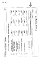
- Fig. 4 shows an example employing a human interface (selected screen) that specifies an intermediate value according to a slider-type software component. A parameter set giving priority to speed and a parameter set giving priority to accuracy are prepared, and the values of these parameter sets are used as values at the both ends, so that the intermediate value can be determined based on the position of a slider (refer to the arrow), that the operator specifies using a mouse, for example.
- the specification and alteration of the interpolation coefficient S can be carried out not only from the manual input device 11 of the CNC 1 or the manual input device 4 of the personal computer 3, but also from the machining program.
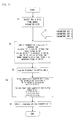
- FIG. 3 shows an outline of the process for adjustment of the parameter set using the interpolation coefficient S.
- the main points of each step are as follows.
- Step S1 Any two parameter sets are selected from the group of parameter sets. Note that the two parameter sets can be selected by the operator using the manual input device 11 of the CNC 1.
- Step S2 The selected parameter sets are copied to the internal RAM inside the memory of the CNC 1.
- the internal RAM data where the parameter set giving more priority to accuracy is copied is indicated by P, and the data on the internal RAM where the parameter set giving more priority to machining speed is copied is indicated by Q.
- Step S3 The data of the interpolation coefficient S that the operator has specified using the manual input device is read from the memory in the CNC 1.
- Step S5 The parameter set Y that has been obtained is applied to create operating commands, and control is performed.
- the previously-proposed control device of a type that prepares parameter sets to determine control contents of a servo system is improved by making it easy for parameters to be set and adjusted in order to bring about results closer to the conditions desired by the operator. For example, demand for giving "a bit more priority to path accuracy", "a bit more priority to operating speed” or "a bit more priority to shock reduction” can be satisfied.
Landscapes
- Engineering & Computer Science (AREA)
- Human Computer Interaction (AREA)
- Manufacturing & Machinery (AREA)
- Physics & Mathematics (AREA)
- General Physics & Mathematics (AREA)
- Automation & Control Theory (AREA)
- Numerical Control (AREA)
- Control Of Position Or Direction (AREA)
- Control Of Electric Motors In General (AREA)
Abstract
Description

Claims (9)
- A control device comprising a servo control section for driving a servomotor, and a numerical control section for providing operating commands to said servo control section, and which drives and controls a servomotor based on several types of control parameters that regulate the operation of said servo control section and several types of control parameters that regulate the operation of said numerical control section, wherein said control device comprises:means for forming one or more groups with regard to one or more types of said control parameters and storing a plurality of parameter sets each comprising individual parameter values in said groups;means for selecting at least two sets from among said parameter sets; andmeans for setting an index for providing any intermediate value with regard to corresponding parameter values in the two or more parameter sets selected; whereinsaid servomotor is driven and controlled based on the intermediate values of respective parameters in said parameter set, according to said index provided.
- The control device according to Claim 1, wherein a computer is connected to said control device, and said storage means and said means for setting the index are provided in said computer.
- The control device according to Claim 1 or 2, wherein said control parameter set for said numerical control section comprises a combination of at least any one of acceleration and deceleration time constants, corner deceleration, permissible acceleration value, and permissible acceleration change amount.
- The control device according to Claim 1, 2 or 3, wherein said index for setting the intermediate value is an index based on the machining time or the operation time of said machine.
- The control device according to any preceding claim, wherein the index for setting said intermediate value is an index based on the manufacturing accuracy of said machine.
- The control device according to any preceding claim, wherin the index for setting said intermediate value is an index based on the size of the shock accompanying acceleration and deceleration of said machine.
- The control device according to any preceding claim, wherein the intermediate value of said two parameter sets is obtained by intermediate value= (1-S) × α + S × β, where the parameter value of one parameter set is α, the parameter value of the other parameter set is β, and said index is S (0 ≦ S ≦ 1).
- The control device according to any preceding claim, wherein said means for setting an index for providing any intermediate value outputs commands based on a machining program.
- The control device according to any preceding claim, wherein as the means for setting an index for providing any intermediate value, a volume or a software component that can be moved continuously is prepared in said control device or in a computer connected to said control device, and commands are outputted based on the index indicated by this volume or software component.
Applications Claiming Priority (4)
| Application Number | Priority Date | Filing Date | Title |
|---|---|---|---|
| JP2001171122 | 2001-06-06 | ||
| JP2001171122 | 2001-06-06 | ||
| JP2002111159A JP2003058218A (en) | 2001-06-06 | 2002-04-12 | Controller for driving and controlling servo motor |
| JP2002111159 | 2002-04-12 |
Publications (3)
| Publication Number | Publication Date |
|---|---|
| EP1267235A2 true EP1267235A2 (en) | 2002-12-18 |
| EP1267235A3 EP1267235A3 (en) | 2004-09-15 |
| EP1267235B1 EP1267235B1 (en) | 2006-08-02 |
Family
ID=26616439
Family Applications (1)
| Application Number | Title | Priority Date | Filing Date |
|---|---|---|---|
| EP02253821A Expired - Lifetime EP1267235B1 (en) | 2001-06-06 | 2002-05-30 | Control device for driving and controlling a servomotor |
Country Status (4)
| Country | Link |
|---|---|
| US (1) | US6806674B2 (en) |
| EP (1) | EP1267235B1 (en) |
| JP (1) | JP2003058218A (en) |
| DE (1) | DE60213519T2 (en) |
Cited By (1)
| Publication number | Priority date | Publication date | Assignee | Title |
|---|---|---|---|---|
| CN102222143A (en) * | 2011-06-21 | 2011-10-19 | 江苏科技大学 | Spatial spiral line numerical control interpolation system and method of parallel machine tool for machining marine propeller |
Families Citing this family (15)
| Publication number | Priority date | Publication date | Assignee | Title |
|---|---|---|---|---|
| JP2011134169A (en) * | 2009-12-25 | 2011-07-07 | Mitsubishi Heavy Ind Ltd | Control parameter adjusting method and adjusting device |
| JP5568005B2 (en) * | 2010-12-28 | 2014-08-06 | オークマ株式会社 | Apparatus and method for correcting thermal displacement of machine tool |
| TWI454868B (en) | 2012-11-02 | 2014-10-01 | Ind Tech Res Inst | Target-oriented numerical control automatic tuning system and method |
| EP3015929B1 (en) * | 2014-11-03 | 2018-01-03 | Mikron Agie Charmilles AG | Standby control for machine tools |
| JP6010094B2 (en) * | 2014-11-28 | 2016-10-19 | ファナック株式会社 | Numerical control device having parameter setting support function related to cycle time |
| JP6169655B2 (en) | 2015-07-30 | 2017-07-26 | ファナック株式会社 | Machine tool, simulation device, and machine learning device |
| JP6077617B1 (en) | 2015-09-25 | 2017-02-08 | ファナック株式会社 | Machine tools that generate optimal speed distribution |
| JP6219897B2 (en) * | 2015-09-28 | 2017-10-25 | ファナック株式会社 | Machine tools that generate optimal acceleration / deceleration |
| JP6546707B2 (en) * | 2016-12-22 | 2019-07-17 | シチズン時計株式会社 | Machine tool and control device therefor |
| CN109257940A (en) * | 2017-05-15 | 2019-01-22 | 三菱电机株式会社 | Control parameter adjusts device |
| JP7035733B2 (en) * | 2018-03-30 | 2022-03-15 | ブラザー工業株式会社 | Machine tools and smoothing methods |
| TW202022652A (en) | 2018-11-30 | 2020-06-16 | 財團法人工業技術研究院 | Machining parameter adjustment system and maching parameter adjustment method |
| JP7355563B2 (en) | 2019-09-06 | 2023-10-03 | ファナック株式会社 | Control device |
| JP7491678B2 (en) * | 2019-10-11 | 2024-05-28 | ファナック株式会社 | Parameter setting device and parameter setting system for machine tool |
| WO2024062544A1 (en) * | 2022-09-21 | 2024-03-28 | ファナック株式会社 | Display device for machine tool |
Family Cites Families (15)
| Publication number | Priority date | Publication date | Assignee | Title |
|---|---|---|---|---|
| JPH07104682B2 (en) | 1986-06-12 | 1995-11-13 | 三菱重工業株式会社 | Fuzzy controller |
| JPS6421605A (en) | 1987-07-17 | 1989-01-25 | Toshiba Machine Co Ltd | Position controller |
| US5148637A (en) * | 1990-02-27 | 1992-09-22 | Bausch & Lomb Incorporated | Lens edging system with programmable feed and speed control |
| JP2745850B2 (en) * | 1991-03-29 | 1998-04-28 | 三菱電機株式会社 | Numerical control device, numerical control system, method for automatically adjusting control parameters, method for changing feature amount criterion, and method for comprehensively determining a plurality of adjustment conditions |
| JPH06222819A (en) * | 1993-01-26 | 1994-08-12 | Fanuc Ltd | Machining program executing method for nc device |
| JPH08221132A (en) * | 1995-02-10 | 1996-08-30 | Fanuc Ltd | Method and device for automatic adjustment of servo parameter |
| JP3509413B2 (en) * | 1995-10-30 | 2004-03-22 | 株式会社デンソー | Motor control device |
| JPH09212227A (en) * | 1996-02-02 | 1997-08-15 | Fanuc Ltd | Method for setting operation information of machine controlled and driven by numerical controller |
| JPH11156672A (en) * | 1997-08-25 | 1999-06-15 | Yoshiaki Kakino | Numerical control device, and machine tool having it |
| JPH11102211A (en) * | 1997-09-25 | 1999-04-13 | Toshiba Mach Co Ltd | Method and device for servo control |
| JP3297643B2 (en) * | 1997-10-14 | 2002-07-02 | 東芝機械株式会社 | Servo control method and servo control device for feed drive system |
| US5963003A (en) * | 1998-04-22 | 1999-10-05 | Allen-Bradley Company, Llc | Method and apparatus for asynchronous multi-axis servo path planning |
| JP4346824B2 (en) * | 1998-12-24 | 2009-10-21 | 三菱電機株式会社 | Numerical controller |
| JP3189829B2 (en) | 1999-05-26 | 2001-07-16 | 三菱電機株式会社 | Numerical control unit |
| JP2002172543A (en) * | 2000-09-29 | 2002-06-18 | Toyoda Mach Works Ltd | Control parameter setting system and control parameter setting method for machining device |
-
2002
- 2002-04-12 JP JP2002111159A patent/JP2003058218A/en active Pending
- 2002-05-30 DE DE60213519T patent/DE60213519T2/en not_active Expired - Fee Related
- 2002-05-30 EP EP02253821A patent/EP1267235B1/en not_active Expired - Lifetime
- 2002-05-31 US US10/158,143 patent/US6806674B2/en not_active Expired - Fee Related
Cited By (1)
| Publication number | Priority date | Publication date | Assignee | Title |
|---|---|---|---|---|
| CN102222143A (en) * | 2011-06-21 | 2011-10-19 | 江苏科技大学 | Spatial spiral line numerical control interpolation system and method of parallel machine tool for machining marine propeller |
Also Published As
| Publication number | Publication date |
|---|---|
| US20020195983A1 (en) | 2002-12-26 |
| EP1267235A3 (en) | 2004-09-15 |
| EP1267235B1 (en) | 2006-08-02 |
| DE60213519D1 (en) | 2006-09-14 |
| JP2003058218A (en) | 2003-02-28 |
| DE60213519T2 (en) | 2006-11-30 |
| US6806674B2 (en) | 2004-10-19 |
Similar Documents
| Publication | Publication Date | Title |
|---|---|---|
| EP1267235B1 (en) | Control device for driving and controlling a servomotor | |
| DE60115053T2 (en) | Method and system for user support for editing parameter setting | |
| US7155303B2 (en) | Numeric control method and numeric control system | |
| EP3575893B1 (en) | Control parameter computation method and control parameter computation device | |
| US7174226B2 (en) | Numerical controller for carrying out learning control | |
| US7167772B2 (en) | Machining time calculating apparatus | |
| US6401005B1 (en) | Programmable synchronous and asynchronous block execution for a computer numerical control | |
| EP1906285A2 (en) | Numerical controller | |
| JP6356658B2 (en) | Numerical control device with easy press adjustment | |
| US6917850B2 (en) | Motion data command system and control signal definition system for motion program | |
| US9696712B2 (en) | Numerical control device having function of simultaneously executing plurality of commands using data in table format | |
| EP1669828B1 (en) | Synchronous controller | |
| JPH07191728A (en) | Feed rate control method and device in numerical control | |
| US20200117162A1 (en) | Numerical control device | |
| WO1992012469A1 (en) | Method of forming nc data | |
| JPH0752365B2 (en) | Numerical control device | |
| CN106970652B (en) | Motion controller | |
| US5251145A (en) | Decision apparatus for machining steps of numerical control information generating function | |
| EP1746474A1 (en) | Numerical controller with integrated CNC frame and application frame display | |
| JP2000163114A (en) | Acceleration / deceleration processing method in interpolation curve | |
| US5243514A (en) | System for generating numerical control information | |
| JP7086297B2 (en) | Control program improvement device, control program improvement method and control program improvement system | |
| WO2023026484A1 (en) | Evaluation program creation device and computer-readable recording medium recording program | |
| JP3188396B2 (en) | Feed rate control method and apparatus in numerical control | |
| JP2858696B2 (en) | Preview control method |
Legal Events
| Date | Code | Title | Description |
|---|---|---|---|
| PUAI | Public reference made under article 153(3) epc to a published international application that has entered the european phase |
Free format text: ORIGINAL CODE: 0009012 |
|
| AK | Designated contracting states |
Kind code of ref document: A2 Designated state(s): AT BE CH CY DE DK ES FI FR GB GR IE IT LI LU MC NL PT SE TR |
|
| AX | Request for extension of the european patent |
Free format text: AL;LT;LV;MK;RO;SI |
|
| RAP1 | Party data changed (applicant data changed or rights of an application transferred) |
Owner name: FANUC LTD |
|
| PUAL | Search report despatched |
Free format text: ORIGINAL CODE: 0009013 |
|
| AK | Designated contracting states |
Kind code of ref document: A3 Designated state(s): AT BE CH CY DE DK ES FI FR GB GR IE IT LI LU MC NL PT SE TR |
|
| AX | Request for extension of the european patent |
Extension state: AL LT LV MK RO SI |
|
| 17P | Request for examination filed |
Effective date: 20041213 |
|
| AKX | Designation fees paid |
Designated state(s): DE |
|
| GRAP | Despatch of communication of intention to grant a patent |
Free format text: ORIGINAL CODE: EPIDOSNIGR1 |
|
| GRAS | Grant fee paid |
Free format text: ORIGINAL CODE: EPIDOSNIGR3 |
|
| GRAA | (expected) grant |
Free format text: ORIGINAL CODE: 0009210 |
|
| AK | Designated contracting states |
Kind code of ref document: B1 Designated state(s): DE |
|
| REF | Corresponds to: |
Ref document number: 60213519 Country of ref document: DE Date of ref document: 20060914 Kind code of ref document: P |
|
| PLBE | No opposition filed within time limit |
Free format text: ORIGINAL CODE: 0009261 |
|
| STAA | Information on the status of an ep patent application or granted ep patent |
Free format text: STATUS: NO OPPOSITION FILED WITHIN TIME LIMIT |
|
| 26N | No opposition filed |
Effective date: 20070503 |
|
| PGFP | Annual fee paid to national office [announced via postgrant information from national office to epo] |
Ref country code: DE Payment date: 20090529 Year of fee payment: 8 |
|
| PG25 | Lapsed in a contracting state [announced via postgrant information from national office to epo] |
Ref country code: DE Free format text: LAPSE BECAUSE OF NON-PAYMENT OF DUE FEES Effective date: 20101201 |