EP1267047A1 - Exhaust gas purifier for internal combustion engine - Google Patents
Exhaust gas purifier for internal combustion engine Download PDFInfo
- Publication number
- EP1267047A1 EP1267047A1 EP02012935A EP02012935A EP1267047A1 EP 1267047 A1 EP1267047 A1 EP 1267047A1 EP 02012935 A EP02012935 A EP 02012935A EP 02012935 A EP02012935 A EP 02012935A EP 1267047 A1 EP1267047 A1 EP 1267047A1
- Authority
- EP
- European Patent Office
- Prior art keywords
- exhaust gas
- exhaust
- internal combustion
- combustion engine
- ash
- Prior art date
- Legal status (The legal status is an assumption and is not a legal conclusion. Google has not performed a legal analysis and makes no representation as to the accuracy of the status listed.)
- Granted
Links
Images



Classifications
-
- F—MECHANICAL ENGINEERING; LIGHTING; HEATING; WEAPONS; BLASTING
- F01—MACHINES OR ENGINES IN GENERAL; ENGINE PLANTS IN GENERAL; STEAM ENGINES
- F01N—GAS-FLOW SILENCERS OR EXHAUST APPARATUS FOR MACHINES OR ENGINES IN GENERAL; GAS-FLOW SILENCERS OR EXHAUST APPARATUS FOR INTERNAL-COMBUSTION ENGINES
- F01N3/00—Exhaust or silencing apparatus having means for purifying, rendering innocuous, or otherwise treating exhaust
- F01N3/02—Exhaust or silencing apparatus having means for purifying, rendering innocuous, or otherwise treating exhaust for cooling, or for removing solid constituents of, exhaust
- F01N3/021—Exhaust or silencing apparatus having means for purifying, rendering innocuous, or otherwise treating exhaust for cooling, or for removing solid constituents of, exhaust by means of filters
- F01N3/023—Exhaust or silencing apparatus having means for purifying, rendering innocuous, or otherwise treating exhaust for cooling, or for removing solid constituents of, exhaust by means of filters using means for regenerating the filters, e.g. by burning trapped particles
- F01N3/0233—Exhaust or silencing apparatus having means for purifying, rendering innocuous, or otherwise treating exhaust for cooling, or for removing solid constituents of, exhaust by means of filters using means for regenerating the filters, e.g. by burning trapped particles periodically cleaning filter by blowing a gas through the filter in a direction opposite to exhaust flow, e.g. exposing filter to engine air intake
-
- F—MECHANICAL ENGINEERING; LIGHTING; HEATING; WEAPONS; BLASTING
- F01—MACHINES OR ENGINES IN GENERAL; ENGINE PLANTS IN GENERAL; STEAM ENGINES
- F01N—GAS-FLOW SILENCERS OR EXHAUST APPARATUS FOR MACHINES OR ENGINES IN GENERAL; GAS-FLOW SILENCERS OR EXHAUST APPARATUS FOR INTERNAL-COMBUSTION ENGINES
- F01N3/00—Exhaust or silencing apparatus having means for purifying, rendering innocuous, or otherwise treating exhaust
- F01N3/02—Exhaust or silencing apparatus having means for purifying, rendering innocuous, or otherwise treating exhaust for cooling, or for removing solid constituents of, exhaust
- F01N3/021—Exhaust or silencing apparatus having means for purifying, rendering innocuous, or otherwise treating exhaust for cooling, or for removing solid constituents of, exhaust by means of filters
- F01N3/022—Exhaust or silencing apparatus having means for purifying, rendering innocuous, or otherwise treating exhaust for cooling, or for removing solid constituents of, exhaust by means of filters characterised by specially adapted filtering structure, e.g. honeycomb, mesh or fibrous
- F01N3/0222—Exhaust or silencing apparatus having means for purifying, rendering innocuous, or otherwise treating exhaust for cooling, or for removing solid constituents of, exhaust by means of filters characterised by specially adapted filtering structure, e.g. honeycomb, mesh or fibrous the structure being monolithic, e.g. honeycombs
-
- F—MECHANICAL ENGINEERING; LIGHTING; HEATING; WEAPONS; BLASTING
- F01—MACHINES OR ENGINES IN GENERAL; ENGINE PLANTS IN GENERAL; STEAM ENGINES
- F01N—GAS-FLOW SILENCERS OR EXHAUST APPARATUS FOR MACHINES OR ENGINES IN GENERAL; GAS-FLOW SILENCERS OR EXHAUST APPARATUS FOR INTERNAL-COMBUSTION ENGINES
- F01N3/00—Exhaust or silencing apparatus having means for purifying, rendering innocuous, or otherwise treating exhaust
- F01N3/08—Exhaust or silencing apparatus having means for purifying, rendering innocuous, or otherwise treating exhaust for rendering innocuous
- F01N3/0807—Exhaust or silencing apparatus having means for purifying, rendering innocuous, or otherwise treating exhaust for rendering innocuous by using absorbents or adsorbents
- F01N3/0821—Exhaust or silencing apparatus having means for purifying, rendering innocuous, or otherwise treating exhaust for rendering innocuous by using absorbents or adsorbents combined with particulate filter
-
- F—MECHANICAL ENGINEERING; LIGHTING; HEATING; WEAPONS; BLASTING
- F01—MACHINES OR ENGINES IN GENERAL; ENGINE PLANTS IN GENERAL; STEAM ENGINES
- F01N—GAS-FLOW SILENCERS OR EXHAUST APPARATUS FOR MACHINES OR ENGINES IN GENERAL; GAS-FLOW SILENCERS OR EXHAUST APPARATUS FOR INTERNAL-COMBUSTION ENGINES
- F01N3/00—Exhaust or silencing apparatus having means for purifying, rendering innocuous, or otherwise treating exhaust
- F01N3/08—Exhaust or silencing apparatus having means for purifying, rendering innocuous, or otherwise treating exhaust for rendering innocuous
- F01N3/0807—Exhaust or silencing apparatus having means for purifying, rendering innocuous, or otherwise treating exhaust for rendering innocuous by using absorbents or adsorbents
- F01N3/0828—Exhaust or silencing apparatus having means for purifying, rendering innocuous, or otherwise treating exhaust for rendering innocuous by using absorbents or adsorbents characterised by the absorbed or adsorbed substances
- F01N3/0842—Nitrogen oxides
-
- F—MECHANICAL ENGINEERING; LIGHTING; HEATING; WEAPONS; BLASTING
- F01—MACHINES OR ENGINES IN GENERAL; ENGINE PLANTS IN GENERAL; STEAM ENGINES
- F01N—GAS-FLOW SILENCERS OR EXHAUST APPARATUS FOR MACHINES OR ENGINES IN GENERAL; GAS-FLOW SILENCERS OR EXHAUST APPARATUS FOR INTERNAL-COMBUSTION ENGINES
- F01N2570/00—Exhaust treating apparatus eliminating, absorbing or adsorbing specific elements or compounds
- F01N2570/08—Phosphorus
Definitions
- the present invention relates to an exhaust gas purifier for removing particulate matters in exhaust gas discharged from an internal combustion engine.
- an exhaust gas purifier for an internal combustion engine as described in Japanese Patent No. 2722987 was proposed in the past.
- the exhaust gas purifier for an internal combustion engine described in the patent is provided with a particulate filter for collecting particulate matters in exhaust gas in an exhaust passageway of an internal combustion engine and has an NOx absorbent, which absorbs NOx in exhaust gas when an air-fuel ratio of the exhaust gas is lean and emits and reduces absorbed NOx when an oxygen concentration in exhaust gas is low and an absorbent exists, disposed in a position where the NOx absorbent can transfer heat to and from the particulate filter.
- the exhaust gas purifier for an internal combustion engine causes temperature of the particulate filter to rise utilizing heat generated when a reducer burns on the NOx absorbent to thereby burn and remove the particulate matters collected in the particulate filter.
- components such as sulfur (S) , phosphorous (P) , calcium (Ca) and magnesium (Mg) are contained in fuel and lubricating oil of an internal combustion engine, and components contained in blow-by gas (lubricating oil) and components contained in air-fuel mixture combine in a combustion chamber to generate compounds such as calcium sulfate (CaSO 4 ), calcium phosphate (Ca 3 (PO 4 ) 2 ) and magnesium sulfate (MgSO 4 ), which are collected on a particulate filter together with particulate matters (PM) to concentrate as ash.
- S sulfur
- P phosphorous
- Ca calcium
- Mg magnesium
- sulfur (S) since sulfur (S) has a characteristic that it is easily absorbed in soot, sulfur (S) absorbed in a particulate filter together with soot combines with calcium (Ca) and magnesium (Mg) in exhaust gas to generate compounds such as calcium sulfate (CaSO 4 ) and magnesium sulfate (MgSO 4 ), which concentrate as ash.
- Japanese Patent Application Laid-open No. 2001-12229 discloses an exhaust gas purifier for an internal combustion engine, which is provided with a collecting material for collecting particulate matters, the collecting material having loaded therewith a metal having an electronegativity equal to or lower than that of a predetermined component contained in fuel and/or lubricating oil of an internal combustion engine.
- the collecting material is loaded with the metal having an electronegativity equal to or lower than a predetermined component contained in lubricant, preferably a metal having an electronegativity lower than that of the predetermined component and strong ionization tendency.
- a component to be combined combines with the metal rather than with the predetermined component, formation of the ash is inhibited.
- a needle-like crystal of calcium phosphate (Ca 3 (PO 4 ) 2 ) is formed on a surface of a particulate filter loading with a noble metal such as platinum (Pt) and having a catalytic function, whereby a space is generated between purified matters and the noble metal, and the catalytic function may be down by half or lifetime of a catalyst may be shorten.
- a noble metal such as platinum (Pt)
- the present invention has been devised in view of the above-mentioned circumstance and it is an object of the present invention to provide a technology capable of inhibiting generation of ash, in particular, generation of ash due to calcium phosphate (Ca 3 (PO 4 ) 2 ), in an exhaust gas purifier provided with a collecting material for collecting particulate matters contained in exhaust gas that is discharged from an internal combustion engine.
- Ca 3 (PO 4 ) 2 calcium phosphate
- the present invention adopts the following measures in order to solve the above problem.
- the exhaust gas purifier for an internal combustion engine is characterized in that, in an exhaust gas purifier for an internal combustion engine which is provided with a collecting material for collecting particulate matters contained in exhaust discharged from the internal combustion engine, an ash trap for absorbing phosphorous (P) in exhaust gas is provided upstream of the collecting material.
- an ash trap for absorbing phosphorous (P) in exhaust gas is provided upstream of the collecting material.
- the collecting material collects particulate matters contained in exhaust gas discharged from the internal combustion engine.
- the term of the collecting material here may be, for example, an ordinary DPF (Diesel Particulate Filter) for collecting particulate matters or a DPF loaded with a catalytic substance such as a NOx absorbent.
- a given components of those components may combine with another component (hereinafter referred to as a combined component) on the collecting material to form ash.
- a combined component another component on the collecting material to form ash.
- the ash trap is provided upstream of the collecting material, since the phosphor (P) is absorbed by the ash trap, formation of ash can be restrained by the collecting material provided downstream of the ash trap.
- This ash trap may be loaded with a basic metal with strong ionization tendency. In this way, it becomes possible to steadily absorb phosphorous (P) in the form of calcium phosphate (Ca 3 (PO 4 ) 2 ) or the like.
- the term of the basic metal here means a metal having an electronegativity such as lithium (Li), sodium (Na), potassium (K) , rubidium (Rb), cesium (Cs), francium (Fr), beryllium (Be), magnesium (Mg), calcium (Ca), strontium (Sr), barium (Ba), radium (Ra) and lanthanum (La), preferably a metal having an electronegativity lower than that of the predetermined component and having strong ionization tendency. Since phosphorous P steadily combines with these metals, formation of ash by calcium phosphate (Ca 3 (PO 4 ) 2 ) in the collecting material downstream of the ash trap is inhibited.
- Ca 3 (PO 4 ) 2 calcium phosphate
- the collecting material it is preferable to load the collecting material with a metal having an electronegativity equal to or lower than a predetermined component contained in fuel or lubricant oil of the internal combustion engine. In this way, it is possible to restrain the concentration on the collecting material as ash consisting of a compound such as calcium sulfate (CaSO 4 ) and magnesium sulfate (MgSO 4 ) which combined sulfur (S) with calcium (Ca) and magnesium (Mg) in exhaust gas.
- a metal having an electronegativity equal to or lower than a predetermined component contained in fuel or lubricant oil of the internal combustion engine In this way, it is possible to restrain the concentration on the collecting material as ash consisting of a compound such as calcium sulfate (CaSO 4 ) and magnesium sulfate (MgSO 4 ) which combined sulfur (S) with calcium (Ca) and magnesium (Mg) in exhaust gas.
- CaSO 4 calcium sulfate
- MgSO 4 magnesium s
- the compounds of the metal loaded on the collecting material and the predetermined component such as sulfur concentrate on the collecting material in the same manner as the ash does, it is preferable to select the metal to be loaded such that these compounds are decomposed or removed under the same conditions as purifying conditions of particulate matters.
- the ash trap may be imparted with an oxidation performance. If the oxidation performance is imparted, since concentration of calcium phosphate (Ca 3 (PO 4 ) 2 ) that is formed by phosphorous and calcium combining with each other is facilitated, it becomes easy to trap phosphorous here.
- an ash trap loaded with a basic metal having an electronegativity that would facilitate combining thereof with phosphorous is provided in a pre-stage of this collecting material so that phosphor is absorbed by this ash trap.
- reference numeral 1 denotes an engine main body
- 2 denotes a cylinder block
- 3 denotes a cylinder head
- 4 denotes a piston
- 5 denotes a combustion chamber
- 6 denotes an electrically-controlled fuel injection valve
- 7 denotes an intake valve
- 8 denotes an intake port
- 9 denotes an exhaust valve
- 10 denotes an exhaust port.
- the intake port 8 is coupled to a surge tank 12 via an intake branch pipe 11 and the surge tank 12 is coupled to a compressor 15 of an exhaust turbocharger 14 via an intake duct 13.
- a throttle valve 17 driven by a step motor 16 is disposed in the intake duct 13 and a cooling device 18 for cooling intake air flowing in the intake duct 13 is disposed around the intake duct 13.
- engine cooling water is guided into the cooling device 18 and the intake air is cooled by the engine cooling water.
- the exhaust port 10 is coupled to an exhaust turbine 21 of the exhaust turbocharger 14 via an exhaust manifold 19 and an exhaust pipe 20.
- the outlet of the exhaust turbine 21 is coupled to an exhaust gas purifier having a casing 23 incorporating a particulate filter 22.
- the exhaust manifold 19 and the surge tank 12 are coupled with each other via an exhaust gas re-circulation (hereinafter referred to as EGR) passageway 24 and an electrically-controlled EGR control valve 25 is disposed in the EGR passageway 24.
- EGR exhaust gas re-circulation
- a cooling device 26 for cooling EGR gas flowing in the EGR passageway 24 is disposed around the EGR passageway 24. In the example shown in Fig. 1, the engine cooling water is guided into the cooling device 26 and the EGR gas is cooled by the engine cooling water.
- each fuel injection valve 6 is coupled to a fuel reservoir, a so-called common-rail 27, via a fuel supply pipe 6a.
- Fuel is supplied into the common-rail 27 from an electrically-controlled fuel pump 28 that can change a discharge amount.
- the fuel supplied to the common-rail 27 is supplied to the fuel injection valve 6 via each fuel supply pipe 6a.
- a fuel pressure sensor 29 for detecting a fuel pressure in the common-rail 27 is attached to the common-rail 27.
- a fuel discharge amount by the fuel pump 28 is controlled such that the fuel pressure in the common-rail 27 becomes equal to a target fuel pressure, based on an output signal of the fuel pressure sensor 29.
- An electronic control unit 30 consists of a digital computer and is provided with an ROM (Read Only Memory) 32, an RAM (Random Access Memory) 33, a CPU (microprocessor) 34, an input port 35 and an output port 36, which are connected with each other by a bidirectional bus 31.
- An output signal of the fuel pressure sensor 29 is inputted in an input port 35 via an corresponding AD converter 37.
- a floor temperature sensor 39 for detecting a floor temperature of the particulate filter 22 is attached to the particulate filter 22.
- An output signal of the floor temperature sensor 39 is inputted in the input port 35 via the corresponding AD converter 37.
- a load sensor 41 for generating an output voltage proportional to an amount of stepping L on an accelerator pedal 40 is connected to the accelerator pedal 40 and an output voltage of the load sensor 41 is inputted in the input port 35 via the corresponding converter 37.
- a crank angle sensor 42 for generating an output pulse each time a crank shaft rotates by, for example, 30°, is connected to the input port 35.
- the output port 36 is connected to the fuel injection valve 6, the step motor 16 for driving a throttle valve, the EGR control valve 25, the fuel pump 28 and an actuator 72 discussed below via a corresponding driving circuit 38.
- an exhaust pipe 70 is connected to the outlet of the exhaust turbine 21.
- the exhaust gas purifier is provided with a first exhaust passageway 76 and a second exhaust passageway 77 which branch from the exhaust pipe 70 to be respectively connected to one side and the other side of the filter 22 in the casing 23 incorporating the particulate filter 22.
- the exhaust gas purifier is provided with a bypass passageway 73 for discharging exhaust gas directly without passing the exhaust gas through the particulate filter 22 from the branch point of the first exhaust passageway 76 and the second exhaust passageway 77.
- an exhaust switching valve 71 is provided in the branch point of the first exhaust passageway 76 and the second exhaust passageway 77.
- the exhaust switching valve 71 is driven by the actuator 72 and alternately switches between first flow (forward flow) in which the first exhaust passageway 76 is selected to flow exhaust gas from one side of the filter 22 and second flow (back flow) in which the second exhaust passageway 77 is selected to flow exhaust gas from the other side of the filter 22.
- ash traps 80 and 81 are respectively provided in a pre-stage of the particulate filter 22 in the first exhaust passageway 76 and the second exhaust passageway 77.
- the ash traps 80 and 81 are loaded with basic metal with strong ionization tendency and phosphorous (P) in exhaust gas is absorbed by the basic metal.
- the basic metal in this context includes, for example, one of lithium (Li), sodium (Na), potassium (K) , rubidium (Rb), cesium (Cs), francium (Fr), beryllium (Be) , magnesium (Mg), calcium (Ca), strontium (Sr), barium (Ba), radium (Ra) and lanthanum (La) or a combination of two or more of these.
- a fuel adding nozzle 83 as reducer adding means for injecting fuel into exhaust gas flowing into the filter 22 is provided in the first exhaust passageway 77.
- the fuel-adding nozzle 83 is controlled by controlling means that is realized on the CPU 34 of the electronic control unit 30.
- the casing 23 for accommodating the filter 22 is disposed in a position right above the exhaust pipe 70 forming the bypass passageway 73.
- the first exhaust passageway 76 and the second exhaust passageway 77 branching from the exhaust pipe 70 are connected to both sides of the casing 23.
- a passing direction of exhaust gas is a length direction
- a length in a width direction perpendicular to the length direction is longer than a length in the length direction.
- the actuator 72 is driven to be controlled by controlling means 75 realized on the CPU 34 of the electronic control unit 30 and is driven by a control signal from the output port 36.
- the actuator 72 is driven by a negative pressure that is formed with driving of the internal combustion engine.
- the actuator 72 controls a valve body into a position for selecting the first exhaust passageway 76 (forward flow position) when a negative pressure is not applied, controls the valve body into a neutral position when a first negative pressure is applied and controls the valve body into a position for selecting the second exhaust passageway 77 (back flow position) when a second negative pressure stronger than the first negative pressure is applied.
- the exhaust switching valve 71 connects the exhaust pipe 70 to the first exhaust passageway 76 and, at the same time, connects the second exhaust passageway 77 to the bypass passageway 73. Therefore, exhaust gas flows in the order of the exhaust pipe 70, the first exhaust passageway 76, the filter 22, the second exhaust passageway 77 and the bypass passageway 73 to be released to the atmosphere.
- the exhaust switching valve 71 connects the exhaust pipe 70 to the second exhaust passageway 77 and, at the same time, connects the first exhaust passageway 76 to the bypass passageway 73. Therefore, exhaust gas flows in the order of exhaust pipe 70, the second exhaust passageway 77, the filter 22, the first exhaust passageway 76 and the bypass passageway 73 to be released to the atmosphere.
- Fig 3A is an image view in the case where exhaust gas is flown through the filter 22 only in one direction.
- particulates since particulates accumulate only on one side of the filter and do not move, particles not only causes increase of a pressure loss of exhaust gas but also hinders purification of the particulates.
- Fig. 3B is an image view in the case where exhaust gas is flown through the filter 22 in the both directions.
- the particulates since particulates are disturbed in the forward flow direction and the back flow direction on both the sides of the filter, the particulates move around on both the side of the filter 22 or in the base material, whereby oxidation of the particulates can be facilitated utilizing active sites existing all over the filter base material and accumulation of the particulates on the filter 22 can be further decreased.
- increase of a pressure loss of exhaust gas can be avoided.
- each of the ash traps 80 and 81 are not specifically limited as long as they can collect particulates, if possible, the ash traps with a large surface area is preferable.
- the ash traps 80 and 81 may be a so-called "wall flow type" which forms a honeycomb structure, in which a porous substance is used as a base material, and in which are alternately arranged, in a honeycomb form, first flow paths with end portions on their upstream sides opened and end portions on their downstream sides blocked, and second flow paths with end portions on their upstream sides blocked and end portions on their downstream sides opened.
- the first flow paths become exhaust gas inflow passageways with their downstream ends blocked by plugs and the second flow paths become exhaust gas outflow passageways with their upstream ends blocked by plugs. These passageways are alternately disposed through thin partitions.
- Phosphorous (P) in exhaust gas is absorbed in the ash traps 80 and 81.
- phosphorous (P) combines with calcium (Ca) and concentrates in the ash traps 80 and 81 in the form of calcium phosphate (Ca 3 (PO 4 ) 2 ). Therefore, in the particulates filter 22 provided downstream of the ash traps 80 and 81, the formation of ash by calcium phosphate (Ca 3 (PO 4 ) 2 ) which is combined phosphorous (P) with calcium (Ca) is restrained.
- the ash traps 80 and 81 may be provided in a pre-stage of a switching flow path, that is, in a pre-stage of the exhaust switching valve 71.
- phosphorous (P) in exhaust gas can be trapped doubly by providing the ash traps also in a pre-stage of the exhaust turbocharger 14. That is, the ash traps exist in both a position close to an exhaust manifold where temperature is high and a position in the first exhaust passageway 76 or the second exhaust passageway 77. Therefore, since they can absorb phosphorous (P) respectively in areas with extremely large temperature difference from each other, trap efficiency is improved.
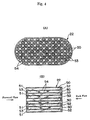
- Fig. 4 shows a structure of the particulate filter 22.
- Fig. 4A shows a front view of the particulate filter 22 and
- Fig. 4B shows a side sectional view of the particulate filter 22.
- the particulate filter 22 forms a honeycomb structure and is of a so-called "wall flow type" provided with a plurality of exhaust flow passageways 50 and 51 extending in parallel with each other.
- These exhaust flow passageways are constituted by the exhaust gas inflow passageways 50 with their downstream ends blocked by plugs 52 and the exhaust gas outflow passageways 51 with their upstream ends blocked by plugs 53. Further, portions with hatching in Fig. 4A indicate the plugs 53.
- the exhaust gas inflow passageways 50 and the exhaust gas outflow passageways 51 are alternately disposed through thin partitions 54.
- the exhaust gas inflow passageways 50 and the exhaust gas outflow passageways 51 are arranged such that each exhaust gas inflow passageway 50 is surrounded by four exhaust gas outflow passageways 51 and each exhaust gas outflow passageway 51 is surrounded by four exhaust gas inflow passageways 50.
- the particulate filter 22 is formed of a porous material such as a cordierite. Therefore, exhaust gas that has flown into the exhaust gas inflow passageways 50 flows out into the adjoining exhaust gas outflow passageways 51 by passing through the partitions 54 around them as indicated by arrows in Fig. 4B.
- layers of a carrier made of, for example, aluminum are formed on circumferential wall surfaces of each exhaust gas inflow passageway 50 and each exhaust gas outflow passageway 51, that is, on both side surfaces of each partition 54 and on internal wall surfaces of pores in the partition 54.
- a noble metal catalyst and an active oxygen releaser for taking in and holding oxygen when excessive oxygen exists around it and releasing the held oxygen in the form of active oxygen when an oxygen concentration falls around it.
- the active oxygen releaser can be constituted by at least one metal selected out of: an alkali metal such as potassium (K), sodium (Na), lithium (Li), cesium (Cs) and rubidium (Rb); an alkali-earth metal such as barium (Ba), calcium (Ca) and strontium (Sr) ; a rare-earth such as lanthanum (La) and yttrium (Y); and a transition metal such as cerium (Ce).
- an alkali metal such as potassium (K), sodium (Na), lithium (Li), cesium (Cs) and rubidium (Rb)
- an alkali-earth metal such as barium (Ba), calcium (Ca) and strontium (Sr)
- a rare-earth such as lanthanum (La) and yttrium (Y)
- a transition metal such as cerium (Ce).
- a valence number of the transition metal (oxygen absorbing agent) such as cerium (Ce) changes according to an oxygen concentration.
- active oxygen is released at a large amount by repeating change in an oxygen concentration as follows.
- the action for removing particulates in exhaust gas by the particulate filter 22 will be described. Further, the action for removing particulates is also performed in the same mechanism even when using other alkali metals, alkali-earth metals, rare-earth or transition metals as the active oxygen releaser.
- Figs. 5A and 5B schematically show enlarged views of the inner circumference surface of the exhaust gas inflow passageway 50 and a surface of a carrier layer formed on the pore inner wall surface within the partition 54.
- reference numeral 60 denotes particles of platinum (Pt) and 61 denotes an active oxygen releaser containing potassium (K).
- a part of the generated nitrogen dioxide (NO 2 ) is absorbed in the active oxygen releaser 61 while being oxidized on the platinum (Pt) and diffuses in the active oxygen releaser 61 in the form of nitrogen oxide ion (NO 3 -) as shown in Fig. 5A while combining with potassium (K) .
- a part of the nitrogen oxide ion (NO 3 -) generates potassium nitrate (KNO 3 ).
- sulfur dioxide (SO 2 ) is also contained in the exhaust gas as described above and this sulfur dioxide (SO 2 ) is also absorbed in the active oxygen releaser 61 by the same mechanism as that for absorbing nitrogen dioxide (NO). That is, oxygen (O 2 ) deposits on the surface of the platinum (Pt) in the form of O 2 - or O 2 - as described above and the SO 2 in the exhaust gas reacts with the O 2 - or O 2 - on the surface of the platinum (Pt) to become (SO 3 ).
- particulates consisting mainly of carbon C are generated in the combustion chamber 5. Therefore, these particulates are contained in exhaust gas. These particulates contained in the exhaust gas contacts and deposits on a surface of a carrier layer, for example, the surface of the active oxygen releaser 61 as indicated by reference numeral 62 in Fig. 5B, when the exhaust gas is flowing through the exhaust gas inflow passageways 50 of the particulate filter 22 or when the exhaust gas moves from the exhaust gas inflow passageway 50 to the exhaust gas outflow passageway 51.
- a carrier layer for example, the surface of the active oxygen releaser 61 as indicated by reference numeral 62 in Fig. 5B
- the oxygen (O) moves to the contact surface between the particulate 62 and the active oxygen releaser 61, and the nitrogen monoxide (NO) is released to the outside from the active oxygen releaser 61.
- the nitrogen monoxide (NO) released to the outside is oxidized on platinum (Pt) on its downstream side and absorbed in the active oxygen releaser 61 again.
- NO in exhaust gas reacts with O 2 - or O 2 - on the surface of platinum Pt to become NO 2 (2NO+O 2 ⁇ 2NO 2 ). Subsequently, a part of the generated (NO 2 ) turns into (NO 3 ) and is absorbed in the active oxygen releaser 61 while being oxidized on platinum (Pt).
- a part of the NO 2 is decomposed by a catalyst and release active oxygen. That is, the NO 2 repeats oxidation and decomposition in such as follows to release active oxygen; 2NO 2 ⁇ NO+O* ⁇ NO+O 2 ⁇ NO+O* ⁇ .
- potassium sulfate (K 2 SO 4 ) formed in the active oxygen releaser 61 is also decomposed into potassium K, oxygen (O) and (SO 2 ).
- the oxygen (O) moves to the contact surface between the particulate 62 and the active oxygen releaser 61 and the SO 2 is released to the outside from the active oxygen releaser 61.
- the (SO 2 ) released to the outside is oxidized on platinum (Pt) on its downstream side and absorbed in the active oxygen releaser 61 again.
- potassium sulfate (K 2 SO 4 ) is stable, it is hard to release active oxygen compared with potassium nitrate (KNO 3 ).
- the Oxygen (O) moving to the contact surface between the particulate 62 and the active oxygen releaser 61 is oxygen decomposed from compounds such as potassium nitrate (KNO 3 ) or potassium sulfate (K 2 SO 4 ).
- the oxygen (O) decomposed from a compound has high energy and has extremely high activity. Therefore, the oxygen moving to the contact surface between the particulate 62 and the active oxygen releaser 61 has turned into active oxygen (O).
- active oxygen (O) contacts the particulate 62 the particulate 62 is oxidized in a short time (within a few minutes to several tens of minutes) without emitting luminous flames and completely disappears. Therefore, the particulate 62 never deposits on the particulate filter 22.
- particulates that deposit on the particulate filter 22 in a laminated shape When particulates that deposit on the particulate filter 22 in a laminated shape is burned in the conventional art, the particulate filter 22 glows and burns accompanied with flames. Such burning accompanied with flames does not continue unless it is under a high temperature. Therefore, temperature of the particulate filter 22 must be maintained high in order to cause the burning accompanied with flames to continue.
- the particulate 62 is oxidized without emitting luminous flames as described above, when the surface of the particulate filter 22 does not glow. That is, in other words, in the present invention, the particulate 62 is oxidized and removed at a considerably low temperature compared with the conventional art. Therefore, a particulate removing action by oxidation of the particulate 62 without emission of luminous flames according to the present invention is completely different from a particulate removing action by burning of the conventional art that is accompanied with flames.
- the particulate removing action by oxidation of particulates is performed at a considerably low temperature. Therefore, the temperature of the particulate filter 22 does not rise so high, whereby there is almost no risk of the particulate filter 22 deteriorating.
- the clogging is caused mainly by calcium sulfate (CaSO 4 ). That is, fuel and lubricating oil contain calcium (Ca) and, therefore, calcium (Ca) is contained in exhaust gas. If SO3 exists, the calcium (Ca) generates calcium sulfate (CaSO 4 ). Calcium sulfate (CaSO 4 ) is solid and is not thermally decomposed even if it is heated. Therefore, when calcium sulfate (CaSO 4 ) is generated and the pores of the particulate filter 22 are blocked by the calcium sulfate (CaSO 4 ), the clogging is caused.
- CaSO 4 calcium sulfate
- potassium sulfate (K 2 SO 4 ) formed on the particulate filter 22 instead of ash has a low concentration compared with calcium sulfate (CaSO 4 ), it can be easily decomposed and removed by raising an atmospheric temperature of the particulate filter 22 or by placing the particulate filter 22 under a reducing atmosphere.
- an amount of discharged particulates M it is almost impossible to reduce an amount of discharged particulates M to be less than an amount of particulates that can be oxidized and removed G in all operation states.
- a temperature of the particulate filter 22 is usually low at the start of an engine. Therefore, the amount of discharged particulates M is usually greater than the amount of particulates that can be oxidized and removed G in this case.
- the amount of discharged particulates M becomes greater than the amount of particulates that can be oxidized and removed G as immediately after the start of an engine, particulates that were not oxidized starts to remain on the particulate filter 22.
- the amount of discharged particulates M is increased to be greater than the amount of particulates that can be oxidized and removed G, and particulates may deposit on the particulate filter 22 in a laminated shape in some cases.
- the switching valve 71 disposed in the exhaust pipe 70 is switched.
- the switching valve 71 is switched, the exhaust upstream side and the exhaust downstream side of the particulate filter 22 are reversed.
- particulates deposit on the surface of the active oxygen releaser 61 and active oxygen (O) is released, whereby the particulates are oxidized and removed.
- a part of the released active oxygen O moves to the exhaust downstream side of the particulate filter 22 together with exhaust gas and oxidize and remove particulates that deposit there.
- the particulates are disturbed in the forward flow direction and the back flow direction on both the side of the particulate filter 22 and move around on both the sides of the particulate filter 22 or inside the base material to meet activated points all over the film base material to be oxidized.
- particulates when particulate that was not oxidized start to deposit on the particulate filter 22, particulates can be completely oxidized and removed from the particulate filter 22 by reversing the exhaust upstream side and the exhaust downstream side of the particulate filter 22.
- the particulates is oxidized without emitting luminous flames by causing an air-fuel ratio of a part of or entire exhaust gas to be rich temporarily.
- the air-fuel ratio of the exhaust gas is made rich, that is, when an oxygen concentration in the exhaust gas is decreased, active oxygen (O) is released to the outside from the active oxygen releaser 61 without interruption.
- the particulates that deposit on the particulate filter 22 is burnt and removed in a short time (within a few minutes to several tens of minutes) without emitting luminous flames.
- a collecting material is described as a material capable of purifying NOx and oxidizing particulates in the above-mentioned embodiment, it is not limited to the above-mentioned one and any material can be adopted as long as it is a filter for collecting particulate matters such as soot and unburnt fuel components in exhaust gas.
- a dummy converter or the like may be further provided upstream of an exhaust system, thereby trapping phosphorous utilizing a characteristic that phosphorous tends to be absorbed in a place where a flow of exhaust gas is disturbed or in a first member.
- a metal having an electronegativity equal to or lower than that of calcium (Ca) and strong ionization tendency e.g., potassium (K)
- a metal having an electronegativity equal to or lower than that of calcium (Ca) and strong ionization tendency e.g., potassium (K)
- a metal having an electronegativity equal to or lower than that of calcium (Ca) and strong ionization tendency e.g., potassium (K)
- K strong ionization tendency
- an ash trap loaded with a basic metal upstream of a collecting material, a component to be combined that forms ash when it combines with a predetermined component is given preference in combining with the metal compared with the predetermined component. Thus, formation of ash is inhibited.
- the exhaust gas purifier provided with the collecting material for collecting particulate matters in exhaust gas, it becomes possible to inhibit formation of ash, so that clogging of the collecting material by ash is prevented and a function of the collecting material can be prevented from being damaged.
Landscapes
- Engineering & Computer Science (AREA)
- Chemical & Material Sciences (AREA)
- Combustion & Propulsion (AREA)
- Mechanical Engineering (AREA)
- General Engineering & Computer Science (AREA)
- Chemical Kinetics & Catalysis (AREA)
- Processes For Solid Components From Exhaust (AREA)
- Exhaust Gas After Treatment (AREA)
- Exhaust Gas Treatment By Means Of Catalyst (AREA)
- Solid-Sorbent Or Filter-Aiding Compositions (AREA)
- Treating Waste Gases (AREA)
Abstract
Description
Claims (6)
- An exhaust gas purifier for an internal combustion engine, comprising
a collecting material for collecting particulate matters contained in exhaust gas discharged from the internal combustion engine and
an ash trap for absorbing phosphorous (P) in exhaust gas being provided upstream of said collecting material. - An exhaust gas purifier for an internal combustion engine according to claim 1,
wherein said ash trap is loaded with basic metal. - An exhaust gas purifier for an internal combustion engine according to claim 1 or 2,
wherein said ash trap is provided with an oxidation performance. - An exhaust gas purifier for an internal combustion engine according to any one of claims 1 to 3,
wherein said collecting material is loaded with metal which have an electronegativity equal to or lower than that of a predetermined component contained in fuel or lubricating oil of the internal combustion engine. - An exhaust gas purifier for an internal combustion engine according to claim 4,
wherein said metal is selected such that compound of said metal and said predetermined component are discomposed or removed under the same conditions as purification conditions of said particulate matters. - An exhaust gas purifier for an internal combustion engine according to claim 1, further comprising
a first exhaust passage way connected to one side of said collecting material,
a second exhaust passage way connected to the other side of said collecting material and
an exhaust switching means for flowing exhaust gas to said first exhaust passage way or second exhaust passage way selectively,
wherein said ash trap is provided in said first exhaust passage way and second exhaust passage way.
Applications Claiming Priority (2)
| Application Number | Priority Date | Filing Date | Title |
|---|---|---|---|
| JP2001179326A JP3632620B2 (en) | 2001-06-13 | 2001-06-13 | Exhaust gas purification device for internal combustion engine |
| JP2001179326 | 2001-06-13 |
Publications (2)
| Publication Number | Publication Date |
|---|---|
| EP1267047A1 true EP1267047A1 (en) | 2002-12-18 |
| EP1267047B1 EP1267047B1 (en) | 2004-08-18 |
Family
ID=19019901
Family Applications (1)
| Application Number | Title | Priority Date | Filing Date |
|---|---|---|---|
| EP20020012935 Expired - Lifetime EP1267047B1 (en) | 2001-06-13 | 2002-06-11 | Exhaust gas purifier for internal combustion engine |
Country Status (3)
| Country | Link |
|---|---|
| EP (1) | EP1267047B1 (en) |
| JP (1) | JP3632620B2 (en) |
| DE (1) | DE60200979T2 (en) |
Cited By (3)
| Publication number | Priority date | Publication date | Assignee | Title |
|---|---|---|---|---|
| EP2299075A1 (en) | 2009-09-22 | 2011-03-23 | Peugeot Citroën Automobiles SA | Exhaust line of a combustion engine |
| US8252374B2 (en) | 2005-10-21 | 2012-08-28 | Toyota Jidosha Kabushiki Kaisha | Particulate matter purifying device and manufacturing method thereof |
| CN121016335A (en) * | 2025-09-05 | 2025-11-28 | 淄博川北化工有限公司 | A waste gas purification device for magnesium sulfate production |
Families Citing this family (4)
| Publication number | Priority date | Publication date | Assignee | Title |
|---|---|---|---|---|
| WO2007055033A1 (en) * | 2005-11-14 | 2007-05-18 | Ibiden Co., Ltd. | Filter, exhaust gas purifying apparatus for internal combustion engine and exhaust gas purifying method |
| US8887495B2 (en) | 2009-07-14 | 2014-11-18 | GM Global Technology Operations LLC | Ash filter, exhaust gas treatment system incorporating the same and method of using the same |
| JP2017227124A (en) * | 2016-06-20 | 2017-12-28 | いすゞ自動車株式会社 | Exhaust gas purification system and phosphorus poisoning suppression method for the same |
| JP7748240B2 (en) * | 2021-09-24 | 2025-10-02 | 株式会社Subaru | Intake and exhaust system |
Citations (4)
| Publication number | Priority date | Publication date | Assignee | Title |
|---|---|---|---|---|
| DE664371C (en) * | 1934-09-15 | 1938-08-25 | Auergesellschaft Akt Ges | Exhaust filter for internal combustion engines |
| US4934142A (en) * | 1987-12-16 | 1990-06-19 | Toyota Jidosha Kabushiki Kaisha | Exhaust emission control device for a diesel engine |
| EP1064984A2 (en) * | 1999-06-23 | 2001-01-03 | Toyota Jidosha Kabushiki Kaisha | Exhaust gas purifier and method for purifying internal combustion engine exhaust gas |
| EP1138890A2 (en) * | 2000-03-27 | 2001-10-04 | Toyota Jidosha Kabushiki Kaisha | Exhaust purifying method and apparatus for an internal combustion engine |
-
2001
- 2001-06-13 JP JP2001179326A patent/JP3632620B2/en not_active Expired - Fee Related
-
2002
- 2002-06-11 EP EP20020012935 patent/EP1267047B1/en not_active Expired - Lifetime
- 2002-06-11 DE DE2002600979 patent/DE60200979T2/en not_active Expired - Lifetime
Patent Citations (4)
| Publication number | Priority date | Publication date | Assignee | Title |
|---|---|---|---|---|
| DE664371C (en) * | 1934-09-15 | 1938-08-25 | Auergesellschaft Akt Ges | Exhaust filter for internal combustion engines |
| US4934142A (en) * | 1987-12-16 | 1990-06-19 | Toyota Jidosha Kabushiki Kaisha | Exhaust emission control device for a diesel engine |
| EP1064984A2 (en) * | 1999-06-23 | 2001-01-03 | Toyota Jidosha Kabushiki Kaisha | Exhaust gas purifier and method for purifying internal combustion engine exhaust gas |
| EP1138890A2 (en) * | 2000-03-27 | 2001-10-04 | Toyota Jidosha Kabushiki Kaisha | Exhaust purifying method and apparatus for an internal combustion engine |
Cited By (4)
| Publication number | Priority date | Publication date | Assignee | Title |
|---|---|---|---|---|
| US8252374B2 (en) | 2005-10-21 | 2012-08-28 | Toyota Jidosha Kabushiki Kaisha | Particulate matter purifying device and manufacturing method thereof |
| EP2299075A1 (en) | 2009-09-22 | 2011-03-23 | Peugeot Citroën Automobiles SA | Exhaust line of a combustion engine |
| FR2950383A1 (en) * | 2009-09-22 | 2011-03-25 | Peugeot Citroen Automobiles Sa | EXHAUST LINE OF A COMBUSTION ENGINE |
| CN121016335A (en) * | 2025-09-05 | 2025-11-28 | 淄博川北化工有限公司 | A waste gas purification device for magnesium sulfate production |
Also Published As
| Publication number | Publication date |
|---|---|
| DE60200979D1 (en) | 2004-09-23 |
| JP2002371824A (en) | 2002-12-26 |
| EP1267047B1 (en) | 2004-08-18 |
| JP3632620B2 (en) | 2005-03-23 |
| DE60200979T2 (en) | 2005-08-18 |
Similar Documents
| Publication | Publication Date | Title |
|---|---|---|
| US6588203B2 (en) | Exhaust device of internal combustion engine | |
| KR100437301B1 (en) | Exhaust gas purification device | |
| US6823665B2 (en) | Exhaust gas purification device | |
| EP1685311B1 (en) | Exhaust purification device of compression ignition type internal combustion engine | |
| KR100878747B1 (en) | An internal combustion engine | |
| KR100950877B1 (en) | Exhaust purifier and exhaust purification method of internal combustion engine | |
| US6874316B2 (en) | Device for purifying the exhaust gas of an internal combustion engine | |
| US6644022B2 (en) | Exhaust gas purification device of internal combustion engine | |
| EP1138890B1 (en) | Exhaust purifying method and apparatus for an internal combustion engine | |
| EP1304454A1 (en) | Exhaust emission control device of internal combustion engine | |
| EP1267047B1 (en) | Exhaust gas purifier for internal combustion engine | |
| JP3514218B2 (en) | Exhaust gas purification device for internal combustion engine | |
| US6837043B2 (en) | Device for purifying the exhaust gas of an internal combustion engine | |
| JP3494114B2 (en) | Exhaust gas purification method and exhaust gas purification device | |
| JP3546950B2 (en) | Exhaust gas purification device for internal combustion engine | |
| JP3565141B2 (en) | Exhaust gas purification device for internal combustion engine | |
| JP3642257B2 (en) | Exhaust gas purification device for internal combustion engine | |
| JP3525850B2 (en) | Exhaust gas purification device for internal combustion engine | |
| JP3546949B2 (en) | Exhaust gas purification device for internal combustion engine | |
| JP3525851B2 (en) | Exhaust gas purification device for internal combustion engine | |
| JP3780859B2 (en) | Exhaust gas purification device for internal combustion engine | |
| JP3539347B2 (en) | Exhaust gas purification device for internal combustion engine | |
| JP3518478B2 (en) | Exhaust gas purification device for internal combustion engine | |
| JP3525852B2 (en) | Exhaust gas purification device for internal combustion engine | |
| JP2005282579A (en) | Exhaust gas purification device for internal combustion engine |
Legal Events
| Date | Code | Title | Description |
|---|---|---|---|
| PUAI | Public reference made under article 153(3) epc to a published international application that has entered the european phase |
Free format text: ORIGINAL CODE: 0009012 |
|
| 17P | Request for examination filed |
Effective date: 20020620 |
|
| AK | Designated contracting states |
Kind code of ref document: A1 Designated state(s): AT BE CH CY DE DK ES FI FR GB GR IE IT LI LU MC NL PT SE TR |
|
| AX | Request for extension of the european patent |
Free format text: AL;LT;LV;MK;RO;SI |
|
| 17Q | First examination report despatched |
Effective date: 20030707 |
|
| AKX | Designation fees paid |
Designated state(s): DE FR |
|
| GRAP | Despatch of communication of intention to grant a patent |
Free format text: ORIGINAL CODE: EPIDOSNIGR1 |
|
| GRAS | Grant fee paid |
Free format text: ORIGINAL CODE: EPIDOSNIGR3 |
|
| GRAA | (expected) grant |
Free format text: ORIGINAL CODE: 0009210 |
|
| AK | Designated contracting states |
Kind code of ref document: B1 Designated state(s): DE FR |
|
| REG | Reference to a national code |
Ref country code: IE Ref legal event code: FG4D |
|
| REF | Corresponds to: |
Ref document number: 60200979 Country of ref document: DE Date of ref document: 20040923 Kind code of ref document: P |
|
| ET | Fr: translation filed | ||
| PLBE | No opposition filed within time limit |
Free format text: ORIGINAL CODE: 0009261 |
|
| STAA | Information on the status of an ep patent application or granted ep patent |
Free format text: STATUS: NO OPPOSITION FILED WITHIN TIME LIMIT |
|
| 26N | No opposition filed |
Effective date: 20050519 |
|
| PGFP | Annual fee paid to national office [announced via postgrant information from national office to epo] |
Ref country code: DE Payment date: 20130605 Year of fee payment: 12 |
|
| PGFP | Annual fee paid to national office [announced via postgrant information from national office to epo] |
Ref country code: FR Payment date: 20130624 Year of fee payment: 12 |
|
| REG | Reference to a national code |
Ref country code: DE Ref legal event code: R119 Ref document number: 60200979 Country of ref document: DE |
|
| REG | Reference to a national code |
Ref country code: FR Ref legal event code: ST Effective date: 20150227 |
|
| REG | Reference to a national code |
Ref country code: DE Ref legal event code: R119 Ref document number: 60200979 Country of ref document: DE Effective date: 20150101 |
|
| PG25 | Lapsed in a contracting state [announced via postgrant information from national office to epo] |
Ref country code: DE Free format text: LAPSE BECAUSE OF NON-PAYMENT OF DUE FEES Effective date: 20150101 |
|
| PG25 | Lapsed in a contracting state [announced via postgrant information from national office to epo] |
Ref country code: FR Free format text: LAPSE BECAUSE OF NON-PAYMENT OF DUE FEES Effective date: 20140630 |