EP1265718B1 - Blank guided forming - Google Patents
Blank guided forming Download PDFInfo
- Publication number
- EP1265718B1 EP1265718B1 EP01908549A EP01908549A EP1265718B1 EP 1265718 B1 EP1265718 B1 EP 1265718B1 EP 01908549 A EP01908549 A EP 01908549A EP 01908549 A EP01908549 A EP 01908549A EP 1265718 B1 EP1265718 B1 EP 1265718B1
- Authority
- EP
- European Patent Office
- Prior art keywords
- workpiece
- zones
- tensile limit
- notches
- along
- Prior art date
- Legal status (The legal status is an assumption and is not a legal conclusion. Google has not performed a legal analysis and makes no representation as to the accuracy of the status listed.)
- Revoked
Links
Images

Classifications
-
- B—PERFORMING OPERATIONS; TRANSPORTING
- B21—MECHANICAL METAL-WORKING WITHOUT ESSENTIALLY REMOVING MATERIAL; PUNCHING METAL
- B21D—WORKING OR PROCESSING OF SHEET METAL OR METAL TUBES, RODS OR PROFILES WITHOUT ESSENTIALLY REMOVING MATERIAL; PUNCHING METAL
- B21D11/00—Bending not restricted to forms of material mentioned in only one of groups B21D5/00, B21D7/00, B21D9/00; Bending not provided for in groups B21D5/00 - B21D9/00; Twisting
- B21D11/20—Bending sheet metal, not otherwise provided for
-
- B—PERFORMING OPERATIONS; TRANSPORTING
- B21—MECHANICAL METAL-WORKING WITHOUT ESSENTIALLY REMOVING MATERIAL; PUNCHING METAL
- B21D—WORKING OR PROCESSING OF SHEET METAL OR METAL TUBES, RODS OR PROFILES WITHOUT ESSENTIALLY REMOVING MATERIAL; PUNCHING METAL
- B21D5/00—Bending sheet metal along straight lines, e.g. to form simple curves
Definitions
- the present invention relates to a blank guided forming or a controlled workpiece shaping of metal, preferably in the form of plates or bands, which metal workpiece has a high tensile limit exceeding 1000 N/mm 2 and is intended to be further shaped. (see for example US-A-5 359 872).
- the shaping methods used today are based on the fact that a workpiece, preferably in the form of plates or bands, is shaped a desired shape in a machine or with a tool, which determins the shape of the final product.
- the shaping method based may be constituted by rolling shaping, pressing, deep drawing etc.
- edge bending/edge folding/edge pressing it is a combination of tools and machinery settings that decide the shape of the final product.
- These previously known shaping methods have a plurality of drawbacks and when three-dimensional shaping, for example the tools are very expensive.
- the shaping ultra-high strength materials having a tensile limit that is greater than 10000 N/mm 2 the shaping is very difficult to carry out and in particular when it comes to making the shaping with narrow radii in the bending operations edge bending, edge folding and rolling shaping.
- the object of the present invention is to provide a controlled work-piece shaping of metal, preferably in the form of plates or bands, where you from a plane or pre-shaped plate workpiece can make possible bending or shaping of two- and three-dimensional shapes in a very simple and reproduceable manner. Furthermore, it is very easy by means of the workpiece according to the invention shape the latter to a final product with relatively simple tool or other devices, in certain cases when the material is thin wall, by hand. By the invention you can now shape ultra high-strength materials with a tensile limit exceeding 1000 N/mm 2 in both two- and three-dimensional shapes, wherein the above enumerated drawbacks are eliminated.
- the features of the invention are stated in the accompanying claims 1 and 7.
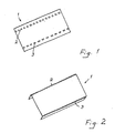
- the method according to the invention means that you make folding/bending notches 2,3 in a workpiece 1 of plate or band shape consisting of a material with a high tensile limit and preferably above 1000 N/mm 2 and which is intended to be further shaped from its original, substantially plane state.
- the yield point of the matrial is reduced by heating to a value, which is substantially lower than the yield point of adjacent base material-
- the workpiece 1 can then subjected to following bending operations.
- the workpiece 1 When the workpiece 1 then has been folded or bended along the heat treated zones 2,3, depending on the direction of the heat treated zones 2;3, which can be straight, curved, formed as a circle segment or extending along an optional curve, the workpiece 1 will bend out of the plane and the entire workpiece 1 then assumes a two- or three-dimensional shape and/or extension.
- a plane or pre-shaped metallic plate workpiece which is intended to be further shaped and which has a tensile limit, preferably above 1000 N/mm 2 the shape of which can be varied and where you have heated one or more narrow elongated zones to a temperature, so that the properties of the material are changed and you achieve a real reduction of the tensile limit of the material along said zones.
- the heat treatment of said zones may take place one- or two-sides, with the aid of a light arc, gas flame, reduction heating, laser, IR, visible or invisible light of all its sorts, hot shoes, induction, etc.
- All machining of the workpiece according to the invention takes place in a machine with the aid of any of the above said heating methods and which delivers the final workpiece, which then is to be shaped.
- the bending radie, to be utilized when shaping the workpiece is determined by the width of the zone that is heat treated. You may vary the width of the zone in its longitudinal direction, which makes possible that the radie of one and the same bending or angle can be varied in the length of the bending. By controlling the heating a variation in the reduction of the tensile limit can be achieved and the tensile limit can also be varied in the direction of the thickness of the plate.
- the heating method of the folding notches or zones in question can take place with the aid of any of the above enumerated methods.
- the pattern that the heat treated folding notches or zones form on the plane or preshaped plate workpiece controls the final shape.
- the workpiece according to the invention is constituted by a metallic material suitable for the object, preferably a thin walI, ultra-high strength stainless material.
Landscapes
- Engineering & Computer Science (AREA)
- Mechanical Engineering (AREA)
- Bending Of Plates, Rods, And Pipes (AREA)
- Magnetic Heads (AREA)
- Transition And Organic Metals Composition Catalysts For Addition Polymerization (AREA)
- Polishing Bodies And Polishing Tools (AREA)
- Nonmetal Cutting Devices (AREA)
- Control Of Cutting Processes (AREA)
Abstract
Description
- Fig. 1
- shows a plane workpiece, which is provided with bending notches according to the invention to accomplish a two-dimensional shape of the final shaped product,
- Fig. 2
- shows the workpiece in fig. 1, after that it has been shaped to the pre-determined shape along the bending notches,
- Fig. 3
- shows another plane workpiece, which is provided with bending notches according to the invention to accomplish a three-dimensional shape of the finally shaped product and
- Fig. 4
- shows the workpiece in Fig. 3, after that it has been shaped to a pre-determined shape along the bending notches.
Claims (8)
- A method of controlled shaping of a metal workpiece, preferably in the form of plates or bands, said metal workpiece is constituted by an ultra-high strength material, having a tensile limit exceeding 1000 N/mm2, and is intended to be further shaped, characterized in that along predetermined folding notches or zones (2,3) across the workpiece (1) when this is in a substantially plane state, said tensile limit of the material is reduced by heating to a tensile limit, which is substantially lower than that of adjacent base material, whereafter the workpiece (1), not until it has got cold, is subjected to subsequent bending, folding or shaping operations to provide a two- or three-dimensional shape and/or extension of the workpiece (1) along the treated folding notches or zones (2,3).
- A method according to claim 1, characterized in that the width of the heat treated zone (2; 3) on the workpiece (1) in question is adapted to a predetermined bending radius.
- A method according to claim 1, characterized in that the width of the heat treated zone (2;3) on the workpiece (1) is varied in the longitudinal direction of the workpiece.
- A method according to claim 1, characterized in that the heating is controlled in response to the desired, varying reduction of the tensile limit of the workpiece (1) and also in response to the thickness of the workpiece (1).
- A method according to claim 1, characterized in that the workpiece (1) is constituted by a thin wall, ultra-high strength metallic material.
- A method according to claim 1, characterized in that the final shape of the workpiece (1) is determined by the pattern that the heat treated notches/zones (2,3) form on the base workpiece.
- A workpiece of metal, preferably in the form of plates or bands, which is constituted by an ultra-high strength material having a tensile limit above 1000 N/mm2 and which is intended to be further shaped, characterized in that the workpiece (1) is constituted by a material, having a tensile limit which is reduced by heating to a tensile limit, which is substantially lower than that of adjacent base material, when the workpiece is cold, along predetermined folding notches or zones (2,3) across the workpiece (1) making possible an easy shaping of the workpiece to a desired two- or three-dimensional shape and/or extension in or along the treated folding notches or zones (2,3).
- A cold workpiece according to claim 7, characterized in that it along the predetermined folding notches or zones (2,3) has been heated on one or two sides by a light arc, gas flame, reduction heating, laser, IR, hot shoes, induction or the like.
Applications Claiming Priority (3)
| Application Number | Priority Date | Filing Date | Title |
|---|---|---|---|
| SE0000570 | 2000-02-22 | ||
| SE0000570A SE0000570L (en) | 2000-02-22 | 2000-02-22 | Subject-controlled shaping |
| PCT/SE2001/000392 WO2001062406A1 (en) | 2000-02-22 | 2001-02-22 | Blank guided forming |
Publications (3)
| Publication Number | Publication Date |
|---|---|
| EP1265718A1 EP1265718A1 (en) | 2002-12-18 |
| EP1265718B1 true EP1265718B1 (en) | 2005-12-28 |
| EP1265718B8 EP1265718B8 (en) | 2006-03-22 |
Family
ID=20278538
Family Applications (1)
| Application Number | Title | Priority Date | Filing Date |
|---|---|---|---|
| EP01908549A Revoked EP1265718B8 (en) | 2000-02-22 | 2001-02-22 | Blank guided forming |
Country Status (9)
| Country | Link |
|---|---|
| US (1) | US6868708B2 (en) |
| EP (1) | EP1265718B8 (en) |
| JP (1) | JP2003523285A (en) |
| AT (1) | ATE314163T1 (en) |
| AU (1) | AU2001236292A1 (en) |
| DE (1) | DE60116270T2 (en) |
| ES (1) | ES2256203T3 (en) |
| SE (2) | SE0000570L (en) |
| WO (1) | WO2001062406A1 (en) |
Families Citing this family (20)
| Publication number | Priority date | Publication date | Assignee | Title |
|---|---|---|---|---|
| CA2601585A1 (en) | 2005-03-17 | 2006-09-28 | Industrial Origami, Llc | Precision-folded, high strength, fatigue-resistant structures and sheet therefor |
| KR20070119047A (en) * | 2005-03-25 | 2007-12-18 | 인더스트리얼 오리가미, 엘엘씨. | Three-dimensional structure formed by precision fold technology and method of forming the |
| US7231800B2 (en) * | 2005-06-09 | 2007-06-19 | Hewlett-Packard Deveopment Company, L.P. | Method for fabricating an exterior part of a camera |
| DE102005051403B3 (en) * | 2005-10-25 | 2007-03-15 | Benteler Automobiltechnik Gmbh | B-column manufacturing method for motor vehicle, involves inserting mold in sectional zone of plate before or during heat formation, and cutting sectional zone after heat formation in mold |
| TW200833434A (en) * | 2006-09-04 | 2008-08-16 | Ind Origami Inc | Apparatus for forming large-radii curved surfaces and small-radii creases in sheet material |
| JP2010508150A (en) | 2006-10-26 | 2010-03-18 | インダストリアル オリガミ インコーポレイテッド | Method for forming planar sheet material into a three-dimensional structure |
| CN101652597A (en) | 2007-02-09 | 2010-02-17 | 奥里加米工业股份有限公司 | Load-carrying 3D structures |
| US20090205387A1 (en) * | 2008-02-16 | 2009-08-20 | Industrial Origami, Inc. | System for low-force roll folding and methods thereof |
| DE102008044523B4 (en) * | 2008-09-15 | 2011-06-16 | Thyssenkrupp Steel Europe Ag | Warmumformprofile |
| WO2010093710A1 (en) * | 2009-02-10 | 2010-08-19 | Industrial Origami, Inc. | Sheet of material with bend-controlling structures and method |
| JP5515566B2 (en) * | 2009-09-29 | 2014-06-11 | Jfeスチール株式会社 | Bent member forming method, bent member and bent member manufacturing method |
| DE102010011368B4 (en) | 2010-03-12 | 2014-03-20 | Benteler Automobiltechnik Gmbh | Process for the production of press-hardened molded components |
| US8624467B2 (en) * | 2010-05-18 | 2014-01-07 | Mindray Medical Sweden Ab | Methods, systems, and devices for mechanical motion amplification |
| DE102011080824A1 (en) * | 2011-08-11 | 2013-02-14 | Mahle International Gmbh | Plate heat exchanger |
| JP2013202645A (en) * | 2012-03-28 | 2013-10-07 | Japan Transport Engineering Co | Method of working metallic material |
| US8936164B2 (en) * | 2012-07-06 | 2015-01-20 | Industrial Origami, Inc. | Solar panel rack |
| JP6086980B2 (en) | 2013-05-31 | 2017-03-01 | 日立オートモティブシステムズ株式会社 | Disc brake |
| CN103658265A (en) * | 2013-11-28 | 2014-03-26 | 浙江鸿峰铝业有限公司 | Method for manufacturing back steel plate with curvature |
| JP7207283B2 (en) * | 2019-01-25 | 2023-01-18 | トヨタ自動車株式会社 | Forming method of steel plate |
| EP3685933B1 (en) | 2019-01-25 | 2021-09-08 | Toyota Jidosha Kabushiki Kaisha | Method for processing steel plate |
Family Cites Families (21)
| Publication number | Priority date | Publication date | Assignee | Title |
|---|---|---|---|---|
| US2813049A (en) * | 1953-01-09 | 1957-11-12 | Jr Edward M Maccutcheon | Method for preventing rupture of metal structures |
| US3790744A (en) * | 1971-07-19 | 1974-02-05 | American Can Co | Method of forming a line of weakness in a multilayer laminate |
| GB1363257A (en) * | 1971-11-04 | 1974-08-14 | Isc Alloys Ltd | Working of alloy sheet material |
| US4120187A (en) * | 1977-05-24 | 1978-10-17 | General Dynamics Corporation | Forming curved segments from metal plates |
| US5228324A (en) * | 1987-11-26 | 1993-07-20 | Polska Akademia Nauk-Instytut Podstawowych Problemow Techniki | Method of bending metal objects |
| US5058408A (en) * | 1990-01-30 | 1991-10-22 | Aluminum Company Of America | Method for partially annealing the sidewall of a container |
| DE4228528A1 (en) | 1991-08-29 | 1993-03-04 | Okuma Machinery Works Ltd | METHOD AND DEVICE FOR METAL SHEET PROCESSING |
| JPH05177366A (en) * | 1991-12-26 | 1993-07-20 | Okuma Mach Works Ltd | Sheet metal working method |
| EP0575646A1 (en) * | 1992-06-22 | 1993-12-29 | Aliteco Ag | A method and a device for forming various workpieces |
| US5719374A (en) * | 1993-03-25 | 1998-02-17 | Centrum Laserowych Technologii Metali Politechniki Swietokrzyskiej W Kielcach I Polskiej Akademii Nauk | Method of bending metal objects with an energy beam |
| SE503417C2 (en) * | 1994-09-21 | 1996-06-10 | Electrolux Ab | Method and apparatus for forming objects by superplastic molding |
| DE19620196A1 (en) * | 1996-05-20 | 1997-11-27 | Audi Ag | Process for forming a flat metal workpiece |
| DE19653543A1 (en) * | 1996-12-20 | 1998-06-25 | Audi Ag | Process for producing a sheet metal part by deep drawing |
| AT407615B (en) * | 1997-07-02 | 2001-05-25 | Inst Spanlose Fertigung Und Ho | METHOD FOR BENDING WITH LASER SUPPORT |
| DE19853365A1 (en) * | 1998-11-19 | 2000-05-25 | Schuler Pressen Gmbh & Co | Method and device for forming |
| DE19853366B4 (en) * | 1998-11-19 | 2007-07-19 | Schuler Pressen Gmbh & Co. Kg | Apparatus and method for forming |
| US6349586B1 (en) * | 1999-02-23 | 2002-02-26 | Ball Corporation | Apparatus and method for annealing container side wall edge for necking |
| US6412325B1 (en) * | 1999-03-23 | 2002-07-02 | 3 Dimensional Services | Method for phototyping parts from sheet metal |
| WO2001005549A2 (en) * | 1999-07-19 | 2001-01-25 | The Regents Of The University Of California | Contour forming of metals by laser peening |
| DE10042197B4 (en) * | 2000-08-28 | 2005-04-07 | Schuler Held Lasertechnik Gmbh & Co. Kg | Laser stretch-stretching processing device for sheet metal parts and methods |
| JP2002260358A (en) * | 2001-02-28 | 2002-09-13 | Tdk Corp | Method and apparatus for adjusting load of suspension |
-
2000
- 2000-02-22 SE SE0000570A patent/SE0000570L/en not_active IP Right Cessation
- 2000-02-22 SE SE516374D patent/SE516374C2/en not_active IP Right Cessation
-
2001
- 2001-02-22 AT AT01908549T patent/ATE314163T1/en not_active IP Right Cessation
- 2001-02-22 ES ES01908549T patent/ES2256203T3/en not_active Expired - Lifetime
- 2001-02-22 JP JP2001561457A patent/JP2003523285A/en active Pending
- 2001-02-22 WO PCT/SE2001/000392 patent/WO2001062406A1/en not_active Ceased
- 2001-02-22 EP EP01908549A patent/EP1265718B8/en not_active Revoked
- 2001-02-22 DE DE60116270T patent/DE60116270T2/en not_active Revoked
- 2001-02-22 US US10/204,926 patent/US6868708B2/en not_active Expired - Fee Related
- 2001-02-22 AU AU2001236292A patent/AU2001236292A1/en not_active Abandoned
Also Published As
| Publication number | Publication date |
|---|---|
| US6868708B2 (en) | 2005-03-22 |
| DE60116270D1 (en) | 2006-02-02 |
| ATE314163T1 (en) | 2006-01-15 |
| SE0000570D0 (en) | 2000-02-22 |
| ES2256203T3 (en) | 2006-07-16 |
| DE60116270T2 (en) | 2006-08-24 |
| WO2001062406A1 (en) | 2001-08-30 |
| EP1265718A1 (en) | 2002-12-18 |
| US20030029216A1 (en) | 2003-02-13 |
| SE516374C2 (en) | 2002-01-08 |
| SE0000570L (en) | 2001-08-23 |
| AU2001236292A1 (en) | 2001-09-03 |
| EP1265718B8 (en) | 2006-03-22 |
| JP2003523285A (en) | 2003-08-05 |
Similar Documents
| Publication | Publication Date | Title |
|---|---|---|
| US6868708B2 (en) | Blank guided forming | |
| CA2610378C (en) | Method for producing a metallic component comprising adjoining portions having differing material properties | |
| KR101148379B1 (en) | Stir forming apparatus and method | |
| CA2688043C (en) | Integrated die trim and method | |
| US10226809B2 (en) | Method for producing a shaped sheet metal part having wall thicknesses differing from each other by region, and axle subframe | |
| CN105363864B (en) | Thermoforming apparatus and method for producing press-quenched formed parts from steel sheets | |
| GB2505048A (en) | Hot shaping die for manufacture of steel shaped parts | |
| CN107980067A (en) | Method and system for heat treatment of sheet metal | |
| JP2003523285A5 (en) | ||
| KR101825427B1 (en) | Method for manufacturing vehicle body parts | |
| US4649607A (en) | Apparatus for making expanded metal | |
| US20180363079A1 (en) | Method and device for heat treating a metal component | |
| EP1332233B1 (en) | Proceeding when producing pieces of metal materials capable of being hardened, a production process and a production line | |
| US5890388A (en) | Method and apparatus for forming structural members | |
| SU1708565A1 (en) | Method of thermal and mechanical treatment of welded joints | |
| KR101738985B1 (en) | Hot formed steel part for vehicles and the method for manufacturing the same | |
| EP0589104B1 (en) | Method of producing tubing | |
| US11904373B2 (en) | Modification of a deep-drawing sheet blank for electric resistance heating | |
| JP3157988B2 (en) | Angle material manufacturing method | |
| JP2025538100A (en) | Process for heat treating a portion of steel and assembly for forming a steel plate | |
| RU2743047C1 (en) | Method for optimized production of a component with at least one formed auxiliary element | |
| JP2019214770A (en) | Surface hardening treatment method for metal work | |
| UA76666C2 (en) | Method of bending of lengthy articles |
Legal Events
| Date | Code | Title | Description |
|---|---|---|---|
| PUAI | Public reference made under article 153(3) epc to a published international application that has entered the european phase |
Free format text: ORIGINAL CODE: 0009012 |
|
| 17P | Request for examination filed |
Effective date: 20020827 |
|
| AK | Designated contracting states |
Kind code of ref document: A1 Designated state(s): AT BE CH CY DE DK ES FI FR GB GR IE IT LI LU MC NL PT SE TR |
|
| AX | Request for extension of the european patent |
Free format text: AL;LT;LV;MK;RO;SI |
|
| 17Q | First examination report despatched |
Effective date: 20040628 |
|
| GRAP | Despatch of communication of intention to grant a patent |
Free format text: ORIGINAL CODE: EPIDOSNIGR1 |
|
| GRAS | Grant fee paid |
Free format text: ORIGINAL CODE: EPIDOSNIGR3 |
|
| GRAA | (expected) grant |
Free format text: ORIGINAL CODE: 0009210 |
|
| AK | Designated contracting states |
Kind code of ref document: B1 Designated state(s): AT BE CH CY DE DK ES FI FR GB GR IE IT LI LU MC NL PT SE TR |
|
| PG25 | Lapsed in a contracting state [announced via postgrant information from national office to epo] |
Ref country code: NL Free format text: LAPSE BECAUSE OF FAILURE TO SUBMIT A TRANSLATION OF THE DESCRIPTION OR TO PAY THE FEE WITHIN THE PRESCRIBED TIME-LIMIT Effective date: 20051228 Ref country code: CH Free format text: LAPSE BECAUSE OF FAILURE TO SUBMIT A TRANSLATION OF THE DESCRIPTION OR TO PAY THE FEE WITHIN THE PRESCRIBED TIME-LIMIT Effective date: 20051228 Ref country code: BE Free format text: LAPSE BECAUSE OF FAILURE TO SUBMIT A TRANSLATION OF THE DESCRIPTION OR TO PAY THE FEE WITHIN THE PRESCRIBED TIME-LIMIT Effective date: 20051228 Ref country code: LI Free format text: LAPSE BECAUSE OF FAILURE TO SUBMIT A TRANSLATION OF THE DESCRIPTION OR TO PAY THE FEE WITHIN THE PRESCRIBED TIME-LIMIT Effective date: 20051228 Ref country code: AT Free format text: LAPSE BECAUSE OF FAILURE TO SUBMIT A TRANSLATION OF THE DESCRIPTION OR TO PAY THE FEE WITHIN THE PRESCRIBED TIME-LIMIT Effective date: 20051228 Ref country code: FI Free format text: LAPSE BECAUSE OF FAILURE TO SUBMIT A TRANSLATION OF THE DESCRIPTION OR TO PAY THE FEE WITHIN THE PRESCRIBED TIME-LIMIT Effective date: 20051228 |
|
| REG | Reference to a national code |
Ref country code: GB Ref legal event code: FG4D |
|
| REG | Reference to a national code |
Ref country code: CH Ref legal event code: EP |
|
| REG | Reference to a national code |
Ref country code: IE Ref legal event code: FG4D |
|
| REF | Corresponds to: |
Ref document number: 60116270 Country of ref document: DE Date of ref document: 20060202 Kind code of ref document: P |
|
| RAP2 | Party data changed (patent owner data changed or rights of a patent transferred) |
Owner name: OUTOKUMPU STAINLESS AB |
|
| PG25 | Lapsed in a contracting state [announced via postgrant information from national office to epo] |
Ref country code: IE Free format text: LAPSE BECAUSE OF NON-PAYMENT OF DUE FEES Effective date: 20060222 |
|
| PG25 | Lapsed in a contracting state [announced via postgrant information from national office to epo] |
Ref country code: LU Free format text: LAPSE BECAUSE OF NON-PAYMENT OF DUE FEES Effective date: 20060228 Ref country code: MC Free format text: LAPSE BECAUSE OF NON-PAYMENT OF DUE FEES Effective date: 20060228 |
|
| PGFP | Annual fee paid to national office [announced via postgrant information from national office to epo] |
Ref country code: IT Payment date: 20060228 Year of fee payment: 6 |
|
| PG25 | Lapsed in a contracting state [announced via postgrant information from national office to epo] |
Ref country code: DK Free format text: LAPSE BECAUSE OF FAILURE TO SUBMIT A TRANSLATION OF THE DESCRIPTION OR TO PAY THE FEE WITHIN THE PRESCRIBED TIME-LIMIT Effective date: 20060328 Ref country code: GR Free format text: LAPSE BECAUSE OF FAILURE TO SUBMIT A TRANSLATION OF THE DESCRIPTION OR TO PAY THE FEE WITHIN THE PRESCRIBED TIME-LIMIT Effective date: 20060328 |
|
| REG | Reference to a national code |
Ref country code: SE Ref legal event code: TRGR |
|
| NLT2 | Nl: modifications (of names), taken from the european patent patent bulletin |
Owner name: OUTOKUMPU STAINLESS AB Effective date: 20060201 |
|
| PLBI | Opposition filed |
Free format text: ORIGINAL CODE: 0009260 |
|
| PG25 | Lapsed in a contracting state [announced via postgrant information from national office to epo] |
Ref country code: PT Free format text: LAPSE BECAUSE OF FAILURE TO SUBMIT A TRANSLATION OF THE DESCRIPTION OR TO PAY THE FEE WITHIN THE PRESCRIBED TIME-LIMIT Effective date: 20060529 |
|
| NLV1 | Nl: lapsed or annulled due to failure to fulfill the requirements of art. 29p and 29m of the patents act | ||
| 26 | Opposition filed |
Opponent name: SSAB TUNNPLAT AB Effective date: 20060403 |
|
| REG | Reference to a national code |
Ref country code: CH Ref legal event code: PL |
|
| REG | Reference to a national code |
Ref country code: ES Ref legal event code: FG2A Ref document number: 2256203 Country of ref document: ES Kind code of ref document: T3 |
|
| ET | Fr: translation filed | ||
| PLAX | Notice of opposition and request to file observation + time limit sent |
Free format text: ORIGINAL CODE: EPIDOSNOBS2 |
|
| REG | Reference to a national code |
Ref country code: IE Ref legal event code: MM4A |
|
| PGFP | Annual fee paid to national office [announced via postgrant information from national office to epo] |
Ref country code: GB Payment date: 20070115 Year of fee payment: 7 |
|
| PGFP | Annual fee paid to national office [announced via postgrant information from national office to epo] |
Ref country code: SE Payment date: 20070117 Year of fee payment: 7 |
|
| PGFP | Annual fee paid to national office [announced via postgrant information from national office to epo] |
Ref country code: DE Payment date: 20070118 Year of fee payment: 7 |
|
| PGFP | Annual fee paid to national office [announced via postgrant information from national office to epo] |
Ref country code: ES Payment date: 20070206 Year of fee payment: 7 |
|
| RDAF | Communication despatched that patent is revoked |
Free format text: ORIGINAL CODE: EPIDOSNREV1 |
|
| RDAG | Patent revoked |
Free format text: ORIGINAL CODE: 0009271 |
|
| STAA | Information on the status of an ep patent application or granted ep patent |
Free format text: STATUS: PATENT REVOKED |
|
| 27W | Patent revoked |
Effective date: 20071115 |
|
| GBPR | Gb: patent revoked under art. 102 of the ep convention designating the uk as contracting state |
Free format text: 20071115 |
|
| PGFP | Annual fee paid to national office [announced via postgrant information from national office to epo] |
Ref country code: FR Payment date: 20070111 Year of fee payment: 7 |
|
| PG25 | Lapsed in a contracting state [announced via postgrant information from national office to epo] |
Ref country code: TR Free format text: LAPSE BECAUSE OF FAILURE TO SUBMIT A TRANSLATION OF THE DESCRIPTION OR TO PAY THE FEE WITHIN THE PRESCRIBED TIME-LIMIT Effective date: 20051228 |
|
| REG | Reference to a national code |
Ref country code: SE Ref legal event code: ECNC |
|
| PG25 | Lapsed in a contracting state [announced via postgrant information from national office to epo] |
Ref country code: CY Free format text: LAPSE BECAUSE OF FAILURE TO SUBMIT A TRANSLATION OF THE DESCRIPTION OR TO PAY THE FEE WITHIN THE PRESCRIBED TIME-LIMIT Effective date: 20051228 |
|
| PG25 | Lapsed in a contracting state [announced via postgrant information from national office to epo] |
Ref country code: IT Free format text: LAPSE BECAUSE OF NON-PAYMENT OF DUE FEES Effective date: 20070222 |