EP1265717B1 - Method and device for hot rolling thin strip - Google Patents
Method and device for hot rolling thin strip Download PDFInfo
- Publication number
- EP1265717B1 EP1265717B1 EP00981075A EP00981075A EP1265717B1 EP 1265717 B1 EP1265717 B1 EP 1265717B1 EP 00981075 A EP00981075 A EP 00981075A EP 00981075 A EP00981075 A EP 00981075A EP 1265717 B1 EP1265717 B1 EP 1265717B1
- Authority
- EP
- European Patent Office
- Prior art keywords
- strip
- roll
- work rolls
- nip
- guide
- Prior art date
- Legal status (The legal status is an assumption and is not a legal conclusion. Google has not performed a legal analysis and makes no representation as to the accuracy of the status listed.)
- Expired - Lifetime
Links
- 238000005098 hot rolling Methods 0.000 title claims abstract description 16
- 238000000034 method Methods 0.000 title claims description 9
- 238000005096 rolling process Methods 0.000 claims abstract description 17
- 229910000831 Steel Inorganic materials 0.000 claims abstract description 11
- 230000007547 defect Effects 0.000 claims abstract description 11
- 239000010959 steel Substances 0.000 claims abstract description 11
- 230000009467 reduction Effects 0.000 claims description 15
- 229910001208 Crucible steel Inorganic materials 0.000 claims description 2
- 238000009749 continuous casting Methods 0.000 claims description 2
- 238000002788 crimping Methods 0.000 abstract description 7
- 238000009434 installation Methods 0.000 description 6
- 238000005266 casting Methods 0.000 description 2
- 239000000463 material Substances 0.000 description 2
- 238000005097 cold rolling Methods 0.000 description 1
- 230000006835 compression Effects 0.000 description 1
- 238000007906 compression Methods 0.000 description 1
- 238000011161 development Methods 0.000 description 1
- 230000018109 developmental process Effects 0.000 description 1
- 238000007493 shaping process Methods 0.000 description 1
Images

Classifications
-
- B—PERFORMING OPERATIONS; TRANSPORTING
- B21—MECHANICAL METAL-WORKING WITHOUT ESSENTIALLY REMOVING MATERIAL; PUNCHING METAL
- B21B—ROLLING OF METAL
- B21B1/00—Metal-rolling methods or mills for making semi-finished products of solid or profiled cross-section; Sequence of operations in milling trains; Layout of rolling-mill plant, e.g. grouping of stands; Succession of passes or of sectional pass alternations
- B21B1/46—Metal-rolling methods or mills for making semi-finished products of solid or profiled cross-section; Sequence of operations in milling trains; Layout of rolling-mill plant, e.g. grouping of stands; Succession of passes or of sectional pass alternations for rolling metal immediately subsequent to continuous casting
-
- B—PERFORMING OPERATIONS; TRANSPORTING
- B21—MECHANICAL METAL-WORKING WITHOUT ESSENTIALLY REMOVING MATERIAL; PUNCHING METAL
- B21B—ROLLING OF METAL
- B21B37/00—Control devices or methods specially adapted for metal-rolling mills or the work produced thereby
- B21B37/28—Control of flatness or profile during rolling of strip, sheets or plates
-
- B—PERFORMING OPERATIONS; TRANSPORTING
- B21—MECHANICAL METAL-WORKING WITHOUT ESSENTIALLY REMOVING MATERIAL; PUNCHING METAL
- B21B—ROLLING OF METAL
- B21B1/00—Metal-rolling methods or mills for making semi-finished products of solid or profiled cross-section; Sequence of operations in milling trains; Layout of rolling-mill plant, e.g. grouping of stands; Succession of passes or of sectional pass alternations
- B21B1/46—Metal-rolling methods or mills for making semi-finished products of solid or profiled cross-section; Sequence of operations in milling trains; Layout of rolling-mill plant, e.g. grouping of stands; Succession of passes or of sectional pass alternations for rolling metal immediately subsequent to continuous casting
- B21B1/463—Metal-rolling methods or mills for making semi-finished products of solid or profiled cross-section; Sequence of operations in milling trains; Layout of rolling-mill plant, e.g. grouping of stands; Succession of passes or of sectional pass alternations for rolling metal immediately subsequent to continuous casting in a continuous process, i.e. the cast not being cut before rolling
-
- B—PERFORMING OPERATIONS; TRANSPORTING
- B21—MECHANICAL METAL-WORKING WITHOUT ESSENTIALLY REMOVING MATERIAL; PUNCHING METAL
- B21B—ROLLING OF METAL
- B21B1/00—Metal-rolling methods or mills for making semi-finished products of solid or profiled cross-section; Sequence of operations in milling trains; Layout of rolling-mill plant, e.g. grouping of stands; Succession of passes or of sectional pass alternations
- B21B1/22—Metal-rolling methods or mills for making semi-finished products of solid or profiled cross-section; Sequence of operations in milling trains; Layout of rolling-mill plant, e.g. grouping of stands; Succession of passes or of sectional pass alternations for rolling plates, strips, bands or sheets of indefinite length
- B21B2001/225—Metal-rolling methods or mills for making semi-finished products of solid or profiled cross-section; Sequence of operations in milling trains; Layout of rolling-mill plant, e.g. grouping of stands; Succession of passes or of sectional pass alternations for rolling plates, strips, bands or sheets of indefinite length by hot-rolling
-
- B—PERFORMING OPERATIONS; TRANSPORTING
- B21—MECHANICAL METAL-WORKING WITHOUT ESSENTIALLY REMOVING MATERIAL; PUNCHING METAL
- B21B—ROLLING OF METAL
- B21B15/00—Arrangements for performing additional metal-working operations specially combined with or arranged in, or specially adapted for use in connection with, metal-rolling mills
- B21B2015/0071—Levelling the rolled product
-
- B—PERFORMING OPERATIONS; TRANSPORTING
- B21—MECHANICAL METAL-WORKING WITHOUT ESSENTIALLY REMOVING MATERIAL; PUNCHING METAL
- B21B—ROLLING OF METAL
- B21B39/00—Arrangements for moving, supporting, or positioning work, or controlling its movement, combined with or arranged in, or specially adapted for use in connection with, metal-rolling mills
- B21B39/006—Pinch roll sets
-
- B—PERFORMING OPERATIONS; TRANSPORTING
- B21—MECHANICAL METAL-WORKING WITHOUT ESSENTIALLY REMOVING MATERIAL; PUNCHING METAL
- B21B—ROLLING OF METAL
- B21B39/00—Arrangements for moving, supporting, or positioning work, or controlling its movement, combined with or arranged in, or specially adapted for use in connection with, metal-rolling mills
- B21B39/02—Feeding or supporting work; Braking or tensioning arrangements, e.g. threading arrangements
- B21B39/08—Braking or tensioning arrangements
-
- B—PERFORMING OPERATIONS; TRANSPORTING
- B21—MECHANICAL METAL-WORKING WITHOUT ESSENTIALLY REMOVING MATERIAL; PUNCHING METAL
- B21B—ROLLING OF METAL
- B21B45/00—Devices for surface or other treatment of work, specially combined with or arranged in, or specially adapted for use in connection with, metal-rolling mills
- B21B45/008—Heat shields
-
- Y—GENERAL TAGGING OF NEW TECHNOLOGICAL DEVELOPMENTS; GENERAL TAGGING OF CROSS-SECTIONAL TECHNOLOGIES SPANNING OVER SEVERAL SECTIONS OF THE IPC; TECHNICAL SUBJECTS COVERED BY FORMER USPC CROSS-REFERENCE ART COLLECTIONS [XRACs] AND DIGESTS
- Y02—TECHNOLOGIES OR APPLICATIONS FOR MITIGATION OR ADAPTATION AGAINST CLIMATE CHANGE
- Y02P—CLIMATE CHANGE MITIGATION TECHNOLOGIES IN THE PRODUCTION OR PROCESSING OF GOODS
- Y02P70/00—Climate change mitigation technologies in the production process for final industrial or consumer products
- Y02P70/10—Greenhouse gas [GHG] capture, material saving, heat recovery or other energy efficient measures, e.g. motor control, characterised by manufacturing processes, e.g. for rolling metal or metal working
Definitions
- This invention relates to a method according to claim 1 and to an apparatus according to claim 6 for hot rolling of thin strip. More particularly, it is concerned with in-line hot rolling of thin steel strip produced by a twin roll strip caster. Twin roll strip casters are described in EP-A 0450775, EP-A 0947261 and WO-A 01/96047.
- Buckling of the hot strips arises due to variations in the strip reduction across the width of the strip.
- the centre part of the strip will be subjected to higher percentage reduction than the strip edges depending on incoming strip profile.
- the centre parts of the strip will therefore be subject to lengthwise compression whereas the edges will be subjected to tension. This results in backwards slip of the central portion of the strip relative to the edges.
- the centre of the strip is thus pushed back relative to the edges to create buckling.
- the buckles are then rolled into the strip to create marks on the surface. In extreme cases the strip may completely fold over at the buckles and the folded over material is rolled in to produce severe defects.
- Variations in strip reduction across the strip width can be localised to small parts of the strip width. This can result in localised buckling of the strip.
- the extent of the buckling is related to the size of the difference in reduction across the strip width and the size of the strip width affected by the difference in reduction.
- Buckling of the strip can be reduced by application of strip tension. However it is difficult to apply high tensions to strip exiting a strip caster since little or no tension can be applied to the strip exiting the casting mould.
- the strip may hang in a free loop and be in a low tensioned state prior to passing to an in-line rolling mill.
- the present invention provides a method and apparatus by which buckling defects can be substantially controlled without the need for high strip tension.
- the buckling defects may be controlled and reduced by passing the strip leaving the caster around a guide roll in advance of the work rolls so as to cause the strip to be wrapped on to one of the work rolls in advance of its entry into the nip between the work rolls.
- the wrapping of the steel strip on to the work roll holds and supports the strip against differential backwards slip relative to the edges caused by variation in strip reduction across the width of the strip.
- Strip guide rolls have previously been used in cold rolling mills which carry out multi-stage reductions with high pretensioning of the strip. In these applications, crimping defects can arise if the strip is not flat when entering the work roll bite and an anti-crimping roll may be used simply to flatten the cold strip entering the bite.
- anti-crimping roll of this kind is disclosed in JP (A) 55106619.
- anti-crimping rolls are not used in applications where there is extensive single pass reduction under very low tension and prior to the present invention, use of guide rolls in hot rolling applications has not been contemplated.
- a method of producing thin steel strip of the kind in which the strip is produced by continuous casting in a twin-roll strip caster to a thickness of 5mm or less and is reduced in thickness by reduction in an in-line hot rolling mill as it is produced by the caster by feeding the cast strip through a nip between a pair of work rolls of the rolling mill and applying strip squeezing forces between the work rolls, characterised in that, in order to reduce strip defects arising during hot rolling due to backwards slipping of the central portion of the strip relative to the edges caused by variation in strip reduction across the width of the strip, the strip leaving the caster is passed in advance of the work rolls around a guide roll which causes the strip to be wrapped onto one of the work rolls in advance of its entry into the nip between the work rolls.
- the strip is wrapped around said one work roll through an angle of wrap of at least 10°.
- the angle of wrap may for example be in the range 20° to 45°.
- the work rolls are disposed one above the other.
- said guide roll may be positioned to guide the strip upwardly from a horizontal path to the nip and then downwardly about the upper work roll in advance of the nip.
- the invention also provides a apparatus for producing thin steel strip of the kind comprising a twin roll strip caster operable to continuously cast steel strip to a thickness of 5mm or less and a hot rolling mill installed in-line with the strip caster so as to be operable to reduce the thickness of the strip by hot rolling the strip as it is produced by the caster, said rolling mill comprising a pair of work rolls defining a nip between them to receive the strip, and means to apply squeezing forces between the work rolls, characterised by a guide roll to guide the strip to the nip between the work rolls such that the strip is wrapped onto one of the work rolls in advance of its entry into the nip.
- the work rolls are disposed one above the other and the guide roll is movable from a lowered position in which strip can pass above it in a horizontal path to the nip between the work rolls and a raised operative position in which it lifts the strip above said horizontal path to cause the strip to be wrapped onto the upper work roll in advance of the nip.
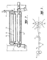
- the drawings illustrate a rolling mill installation to receive thin steel strip 11 produced by a twin roll caster and to reduce the thickness of the strip by in-line hot rolling it as it is produced by the caster.
- the thin steel strip 11 is passed through a pinch roll stand 12 comprising a pair of pinch rolls 13 to which strip gripping forces are applied by a pair of hydraulic cylinder units 14 disposed one to each side of the pinch roll stand.
- the strip 11 After passing through pinch roll stand 12 the strip 11 is supported on a table formed by a succession of rollers 15 across which it passes to a rolling mill 16 comprising a pair of work rolls 17 disposed one above the other and a pair of upper and lower backing rolls 18. Strip reduction forces are applied between the work rolls 17 by means of hydraulic cylinder units (not shown) disposed at the two sides of the rolling mill and acting through the upper backing rolls 18. Between pinch roll stand 12 and rolling mill stand 16, the strip is held within a sealed enclosure 19.
- the installation includes a guide roll 21 located immediately in advance of the rolling mill 16 and mounted on a pair of rocker structures 22 which can be pivoted on horizontal pivot shaft 23 by actuation of a hydraulic cylinder 30 which acts on the rocker structures through a mechanical linkage mechanism 31 so as to enable the guide roll 21 to be raised and lowered.
- the guide roll 21 has a lowered inoperative position (indicated by dotted lines in Figure 1) in which the strip can be passed horizontally directly into the nip 26 between the work rolls 17 of the rolling mill.
- the roll 21 can then be raised by operation of the hydraulic cylinder 30 to lift the strip out of its straight line horizontal path so as to pass around the guide roll and to be wrapped about the upper work roll 17 in advance of the nip 26.
- the guide roll pivot shaft 23 is supported on bearing mounts in the side walls of enclosure 19 and one end that shaft extends through a rotary seal to connect with the linkage mechanism 31 so that the shaft is rotated by the linkage mechanism 31 on operation of hydraulic cylinder 30.
- the effective stroke of hydraulic cylinder 30 can be adjusted by operation of an electric screwjack 32 to set a stop 33 in order to adjust the height of the guide roll 21 in its raised position.
- an upper pass line roll 27 is brought downwardly to engage the strip immediately after one of the table rolls 15.
- Roll 27 is mounted on rocker arms 34 which extend from a pivot shaft 35 connected at one end to a lever arm 36 located outside enclosure 19 and actuable by a hydraulic cylinder 37 to rotate shaft 35 there by to raise and lower the upper pass line roll 27.
- the guide roll is most effective in practice to reduce buckling defects even in very thin strip. Due to the wrapping of the strip around the upper work roll the work roll supports the strip and resists buckling of the strip. The curvature of the strip around the top work roll can also increase the resistance to transverse buckling of the strip in the critical region in advance of the roll nip due to the effectively curved shaping of the strip in that region.
- the strip should be wrapped about the upper work roll through an angle of at least 10° and preferably in the range 20° to 45°.
- the work rolls may have a diameter in the range 400mm to 700mm and the anti-crimp roll may be positioned to raise the strip to a height of between 150mm to 250mm above a horizontal plane through the nip between the work rolls.
Landscapes
- Engineering & Computer Science (AREA)
- Mechanical Engineering (AREA)
- Metal Rolling (AREA)
- Pressure Welding/Diffusion-Bonding (AREA)
- Manufacturing Of Steel Electrode Plates (AREA)
- Continuous Casting (AREA)
Abstract
Description
It has been found that the guide roll is most effective in practice to reduce buckling defects even in very thin strip. Due to the wrapping of the strip around the upper work roll the work roll supports the strip and resists buckling of the strip. The curvature of the strip around the top work roll can also increase the resistance to transverse buckling of the strip in the critical region in advance of the roll nip due to the effectively curved shaping of the strip in that region.
Claims (9)
- A method of producing thin steel strip of the kind in which the strip (11) is produced is produced by continuous casting in a twin-roll strip caster to a thickness of 5mm or less and is reduced in thickness by reduction in an in-line hot rolling mill (16) as it is produced by the caster by feeding the cast strip (11) through a nip between a pair of work rolls (17) of the rolling mill (16) and applying strip squeezing forces between the work rolls, characterised in that, in order to reduce strip defects arising during hot rolling due to backwards slipping of the central portion of the strip (11) relative to the edges caused by variation in strip reduction across the width of the strip, the strip leaving the caster is passed in advance of the work rolls (17) around a guide roll (21) which causes the strip to be wrapped onto one of the work rolls (17) in advance of its entry into the nip (26) between the work rolls (17).
- A method as claimed in claim 1, further characterised in that the strip (11) is wrapped around said one of the work rolls (17) through an angle of wrap of at least 10°.
- A method as claimed in claim 2, further characterised in that the angle of wrap is in the range 20° to 45°.
- A method as claimed in any one of claims 1 to 3, further characterised that the work rolls (17) are disposed one above the other.
- A method as claimed in claim 4, further characterised in that said guide roll (21) is positioned to guide the strip 11 upwardly from a horizontal path to the nip and downwardly about the upper work roll (17) in advance of the nip.
- Apparatus for producing thin steel strip of the kind comprising a twin roll strip caster operable to continuously cast steel strip to a thickness of 5mm or less and a hot rolling mill (16) installed in-line with the strip caster so as to be operable to reduce the thickness of the strip by hot rolling the strip as it is produced by the caster, said rolling mill (16) comprising a pair of work rolls (17) defining a nip (26) between them to receive the strip (11), and means to apply squeezing forces between the work rolls, characterised by a guide roll (21) to guide the strip (16) to the nip (26) between the work rolls (17) such that the strip is wrapped onto one of the work rolls (17) in advance of its entry into the nip (26).
- Apparatus as claimed in claim 6, wherein the guide roll (21) is positionable to guide the strip (11) such that the strip is wrapped onto said one work roll (17) through an angle of wrap of at least 10°.
- Apparatus as claimed in claim 7, wherein the guide roll (21) is positionable to guide the strip (11) such that the strip is wrapped onto said one work roll (17) through an angle of wrap in the range 20° to 45°.
- Apparatus as claimed in any one of claims 6 to 8, wherein the work rolls (17) are disposed one above the other and the guide roll (21) is movable from a lowered position in which strip (11) can pass above it in a horizontal path to the nip (26) between the work rolls and a raised operative position in which it lifts the strip above said horizontal path to cause the strip to be wrapped onto the upper work roll (17) in advance of the nip (26).
Applications Claiming Priority (3)
| Application Number | Priority Date | Filing Date | Title |
|---|---|---|---|
| AUPQ4363A AUPQ436399A0 (en) | 1999-12-01 | 1999-12-01 | Hot rolling thin strip |
| AUPQ436399 | 1999-12-01 | ||
| PCT/AU2000/001477 WO2001039905A1 (en) | 1999-12-01 | 2000-11-30 | Hot rolling thin strip |
Publications (3)
| Publication Number | Publication Date |
|---|---|
| EP1265717A1 EP1265717A1 (en) | 2002-12-18 |
| EP1265717A4 EP1265717A4 (en) | 2003-07-23 |
| EP1265717B1 true EP1265717B1 (en) | 2005-01-12 |
Family
ID=3818505
Family Applications (1)
| Application Number | Title | Priority Date | Filing Date |
|---|---|---|---|
| EP00981075A Expired - Lifetime EP1265717B1 (en) | 1999-12-01 | 2000-11-30 | Method and device for hot rolling thin strip |
Country Status (14)
| Country | Link |
|---|---|
| US (1) | US6745607B2 (en) |
| EP (1) | EP1265717B1 (en) |
| JP (1) | JP4452010B2 (en) |
| KR (1) | KR100710426B1 (en) |
| CN (1) | CN1210116C (en) |
| AT (1) | ATE286788T1 (en) |
| AU (1) | AUPQ436399A0 (en) |
| BR (1) | BR0016002A (en) |
| CA (1) | CA2392825C (en) |
| DE (1) | DE60017469T2 (en) |
| MY (1) | MY125324A (en) |
| RU (1) | RU2257971C2 (en) |
| TW (1) | TW529971B (en) |
| WO (1) | WO2001039905A1 (en) |
Cited By (2)
| Publication number | Priority date | Publication date | Assignee | Title |
|---|---|---|---|---|
| WO2009020619A1 (en) * | 2007-08-06 | 2009-02-12 | H.C. Starck, Inc. | Methods and apparatus for controlling texture of plates and sheets by tilt rolling |
| US8250895B2 (en) | 2007-08-06 | 2012-08-28 | H.C. Starck Inc. | Methods and apparatus for controlling texture of plates and sheets by tilt rolling |
Families Citing this family (19)
| Publication number | Priority date | Publication date | Assignee | Title |
|---|---|---|---|---|
| AUPQ779900A0 (en) | 2000-05-26 | 2000-06-22 | Bhp Steel (Jla) Pty Limited | Hot rolling thin strip |
| US8313374B2 (en) | 2003-02-14 | 2012-11-20 | Wms Gaming Inc. | Gaming machine having improved audio control architecture |
| KR100960387B1 (en) * | 2003-06-13 | 2010-05-28 | 주식회사 포스코 | Under buckle control device for 2 tanks |
| US7741696B2 (en) * | 2004-05-13 | 2010-06-22 | St-Ericsson Sa | Semiconductor integrated circuit including metal mesh structure |
| US7131307B2 (en) * | 2004-06-17 | 2006-11-07 | Outokumpu Oyj | Compact rolling mill and a method of producing a thin strip |
| US9534189B2 (en) * | 2006-05-24 | 2017-01-03 | Nalco Company | Hydraulic fluids and fire-resistant fluids comprising glycerin containing by-products |
| US7207202B1 (en) | 2006-05-30 | 2007-04-24 | Morgan Construction Company | Method of subdividing and decelerating hot rolled long products |
| CN101322976B (en) * | 2008-06-30 | 2010-06-02 | 常熟市双华电子有限公司 | 4-roller cold rolling mill |
| JP5240250B2 (en) * | 2010-01-13 | 2013-07-17 | 富士ゼロックス株式会社 | Cleaning member, charging device, unit for image forming apparatus, process cartridge, and image forming apparatus |
| KR101045611B1 (en) * | 2011-02-17 | 2011-06-30 | 한국엠테크(주) | Anti Crimping Roll Device of Rolling Machine |
| US20120222831A1 (en) * | 2011-03-04 | 2012-09-06 | Nucor Corporation | Method of continuously casting thin strip |
| CN102756013B (en) * | 2011-04-27 | 2014-08-20 | 宝山钢铁股份有限公司 | Improving method and device for warping of cold-rolled strip steel |
| RU2544728C2 (en) * | 2013-04-11 | 2015-03-20 | Федеральное государственное бюджетное образовательное учреждение высшего профессионального образования "Челябинская государственная агроинженерная академия" | Treatment method of metal strap and device for its implementation |
| US9156082B2 (en) | 2013-06-04 | 2015-10-13 | Nucor Corporation | Method of continuously casting thin strip |
| US9412222B2 (en) | 2013-09-20 | 2016-08-09 | Igt | Coordinated gaming machine attract via gaming machine cameras |
| CN104801541A (en) * | 2014-01-23 | 2015-07-29 | 大连理工大学 | Rolling method for preparing high room temperature ductility magnesium alloy panel |
| CN105215061A (en) * | 2015-10-24 | 2016-01-06 | 本钢不锈钢冷轧丹东有限责任公司 | A kind of tension roll assembly |
| RU2701322C1 (en) * | 2019-01-16 | 2019-09-26 | Федеральное государственное бюджетное образовательное учреждение высшего образования "Магнитогорский государственный технический университет им. Г.И. Носова" | Method of producing a thin strip |
| CN111495987A (en) * | 2020-04-30 | 2020-08-07 | 张家港扬子江冷轧板有限公司 | Device for improving hot rolling stability of non-oriented silicon steel and application method thereof |
Family Cites Families (10)
| Publication number | Priority date | Publication date | Assignee | Title |
|---|---|---|---|---|
| JPS55106619A (en) * | 1979-02-09 | 1980-08-15 | Hitachi Ltd | Mill guide device for rolling mill |
| JPS55139102A (en) * | 1979-04-17 | 1980-10-30 | Mitsubishi Heavy Ind Ltd | Rolling method for strip |
| JPS5839001B2 (en) | 1979-06-28 | 1983-08-26 | 石川島播磨重工業株式会社 | Strip winding device for rolling mill rolls |
| SU858955A1 (en) * | 1979-08-17 | 1981-08-30 | за вители А,П. Грудев, А.Д. Размахнин, К. А. Ивано|в В.Г. Шув ков, В.А. Сорокин и Г.В. Фот 5с&. ::п:;;-/7-: | Continuous rolling mill |
| US4291562A (en) * | 1979-09-20 | 1981-09-29 | Orr Howard S | Three roll tension stand |
| JPS5949081B2 (en) * | 1979-10-02 | 1984-11-30 | 古河電気工業株式会社 | Method for improving ingot quality in continuous casting |
| BR8801799A (en) * | 1987-08-26 | 1989-03-21 | Lauener Eng Ag | ARMATION FOR LAMINATION OR LAMINATED FOUNDATION |
| FR2685880B1 (en) * | 1992-01-06 | 1996-07-12 | Clecim Sa | APPARATUS FOR CLEANING A CYLINDRICAL ROLLER, ESPECIALLY A ROLLER ROLLER. |
| RU2058840C1 (en) * | 1994-06-20 | 1996-04-27 | Челябинский государственный технический университет | Strip cold rolling method |
| DE19524729A1 (en) * | 1995-07-07 | 1997-01-16 | Sundwiger Eisen Maschinen | Method and device for rolling strips with a non-uniform thickness and / or length distribution across their width |
-
1999
- 1999-12-01 AU AUPQ4363A patent/AUPQ436399A0/en not_active Abandoned
-
2000
- 2000-11-29 MY MYPI20005573A patent/MY125324A/en unknown
- 2000-11-30 US US10/148,348 patent/US6745607B2/en not_active Expired - Lifetime
- 2000-11-30 AT AT00981075T patent/ATE286788T1/en not_active IP Right Cessation
- 2000-11-30 JP JP2001541629A patent/JP4452010B2/en not_active Expired - Fee Related
- 2000-11-30 RU RU2002117289/02A patent/RU2257971C2/en not_active IP Right Cessation
- 2000-11-30 KR KR1020027006963A patent/KR100710426B1/en not_active Expired - Fee Related
- 2000-11-30 CN CNB008181675A patent/CN1210116C/en not_active Expired - Fee Related
- 2000-11-30 BR BR0016002-4A patent/BR0016002A/en active Search and Examination
- 2000-11-30 WO PCT/AU2000/001477 patent/WO2001039905A1/en not_active Ceased
- 2000-11-30 DE DE60017469T patent/DE60017469T2/en not_active Expired - Lifetime
- 2000-11-30 CA CA002392825A patent/CA2392825C/en not_active Expired - Fee Related
- 2000-11-30 EP EP00981075A patent/EP1265717B1/en not_active Expired - Lifetime
- 2000-12-13 TW TW089125468A patent/TW529971B/en not_active IP Right Cessation
Cited By (6)
| Publication number | Priority date | Publication date | Assignee | Title |
|---|---|---|---|---|
| WO2009020619A1 (en) * | 2007-08-06 | 2009-02-12 | H.C. Starck, Inc. | Methods and apparatus for controlling texture of plates and sheets by tilt rolling |
| US8250895B2 (en) | 2007-08-06 | 2012-08-28 | H.C. Starck Inc. | Methods and apparatus for controlling texture of plates and sheets by tilt rolling |
| KR101365774B1 (en) * | 2007-08-06 | 2014-02-20 | 에이치. 씨. 스타아크 아이앤씨 | Methods and apparatus for controlling texture of plates and sheets by tilt rolling |
| US9095885B2 (en) | 2007-08-06 | 2015-08-04 | H.C. Starck Inc. | Refractory metal plates with improved uniformity of texture |
| EP2998039A1 (en) * | 2007-08-06 | 2016-03-23 | H. C. Starck Inc | Methods and apparatus for controlling texture of plates and sheets by tilt rolling |
| US9767999B2 (en) | 2007-08-06 | 2017-09-19 | H.C. Starck Inc. | Refractory metal plates |
Also Published As
| Publication number | Publication date |
|---|---|
| RU2257971C2 (en) | 2005-08-10 |
| US20030167818A1 (en) | 2003-09-11 |
| BR0016002A (en) | 2002-07-23 |
| DE60017469T2 (en) | 2005-12-22 |
| KR100710426B1 (en) | 2007-04-24 |
| KR20020060770A (en) | 2002-07-18 |
| DE60017469D1 (en) | 2005-02-17 |
| ATE286788T1 (en) | 2005-01-15 |
| EP1265717A4 (en) | 2003-07-23 |
| CN1210116C (en) | 2005-07-13 |
| RU2002117289A (en) | 2004-01-20 |
| EP1265717A1 (en) | 2002-12-18 |
| JP2003515453A (en) | 2003-05-07 |
| TW529971B (en) | 2003-05-01 |
| AUPQ436399A0 (en) | 1999-12-23 |
| WO2001039905A1 (en) | 2001-06-07 |
| CA2392825A1 (en) | 2001-06-07 |
| JP4452010B2 (en) | 2010-04-21 |
| MY125324A (en) | 2006-07-31 |
| US6745607B2 (en) | 2004-06-08 |
| CA2392825C (en) | 2009-10-13 |
| CN1414887A (en) | 2003-04-30 |
Similar Documents
| Publication | Publication Date | Title |
|---|---|---|
| CA2392825C (en) | Hot rolling thin strip | |
| US8365565B2 (en) | System for leveling metal strip | |
| US2332796A (en) | Reduction of elongated bodies | |
| JP4612265B2 (en) | Thin strip hot rolling | |
| CA2463962C (en) | Method and device for the continuous production of a rolled metal strip from a molten metal | |
| US5950476A (en) | Method and apparatus to tension hot strip during coiling | |
| AU784167B2 (en) | Hot rolling thin strip | |
| JPH0797637A (en) | Reel furnace for hot strip | |
| JP2620048B2 (en) | Roll arrangement of gloss machine | |
| KR102904343B1 (en) | System and method for controlling position of anti crimping roll | |
| JP3191469B2 (en) | Width reduction equipment | |
| JPH06210314A (en) | Width reduction press | |
| JPS6013546Y2 (en) | Roller leveler for straightening steel plates | |
| JPS6227285Y2 (en) | ||
| JPS6352702A (en) | Broadside rolling method for continuously cast thin material | |
| JPH04172101A (en) | Slab width reduction method and device | |
| JP2005028397A (en) | Steel strip rolling equipment | |
| JPH074610B2 (en) | Side guide of hot continuous rolling mill | |
| JPH0547281B2 (en) | ||
| JPH11267701A (en) | Hot slab width pressing method | |
| JPH04231157A (en) | Continuous forging of cast strand in continuous casting | |
| JPH0679309A (en) | Corner reduction device | |
| JPH0417902A (en) | Preventing method of meandering of tall end part of rolled stock | |
| JPH02182301A (en) | Method for rolling |
Legal Events
| Date | Code | Title | Description |
|---|---|---|---|
| PUAI | Public reference made under article 153(3) epc to a published international application that has entered the european phase |
Free format text: ORIGINAL CODE: 0009012 |
|
| 17P | Request for examination filed |
Effective date: 20020529 |
|
| AK | Designated contracting states |
Kind code of ref document: A1 Designated state(s): AT BE CH CY DE DK ES FI FR GB GR IE IT LI LU MC NL PT SE TR |
|
| AX | Request for extension of the european patent |
Free format text: AL;LT;LV;MK;RO;SI |
|
| RIC1 | Information provided on ipc code assigned before grant |
Ipc: 7B 21B 1/46 A Ipc: 7B 21B 15/00 B Ipc: 7B 21B 39/02 B |
|
| A4 | Supplementary search report drawn up and despatched |
Effective date: 20030610 |
|
| 17Q | First examination report despatched |
Effective date: 20031219 |
|
| GRAP | Despatch of communication of intention to grant a patent |
Free format text: ORIGINAL CODE: EPIDOSNIGR1 |
|
| RTI1 | Title (correction) |
Free format text: METHOD AND DEVICE FOR HOT ROLLING THIN STRIP |
|
| RIN1 | Information on inventor provided before grant (corrected) |
Inventor name: KATO, HEIJI Inventor name: ZIEGELAAR, JOHN, ALBERT Inventor name: LOPEZ, MICHAEL, ANGEL |
|
| GRAS | Grant fee paid |
Free format text: ORIGINAL CODE: EPIDOSNIGR3 |
|
| GRAA | (expected) grant |
Free format text: ORIGINAL CODE: 0009210 |
|
| AK | Designated contracting states |
Kind code of ref document: B1 Designated state(s): AT BE CH CY DE DK ES FI FR GB GR IE IT LI LU MC NL PT SE TR |
|
| PG25 | Lapsed in a contracting state [announced via postgrant information from national office to epo] |
Ref country code: CH Free format text: LAPSE BECAUSE OF FAILURE TO SUBMIT A TRANSLATION OF THE DESCRIPTION OR TO PAY THE FEE WITHIN THE PRESCRIBED TIME-LIMIT Effective date: 20050112 Ref country code: FI Free format text: LAPSE BECAUSE OF FAILURE TO SUBMIT A TRANSLATION OF THE DESCRIPTION OR TO PAY THE FEE WITHIN THE PRESCRIBED TIME-LIMIT Effective date: 20050112 Ref country code: BE Free format text: LAPSE BECAUSE OF FAILURE TO SUBMIT A TRANSLATION OF THE DESCRIPTION OR TO PAY THE FEE WITHIN THE PRESCRIBED TIME-LIMIT Effective date: 20050112 Ref country code: AT Free format text: LAPSE BECAUSE OF FAILURE TO SUBMIT A TRANSLATION OF THE DESCRIPTION OR TO PAY THE FEE WITHIN THE PRESCRIBED TIME-LIMIT Effective date: 20050112 Ref country code: LI Free format text: LAPSE BECAUSE OF FAILURE TO SUBMIT A TRANSLATION OF THE DESCRIPTION OR TO PAY THE FEE WITHIN THE PRESCRIBED TIME-LIMIT Effective date: 20050112 Ref country code: TR Free format text: LAPSE BECAUSE OF FAILURE TO SUBMIT A TRANSLATION OF THE DESCRIPTION OR TO PAY THE FEE WITHIN THE PRESCRIBED TIME-LIMIT Effective date: 20050112 Ref country code: NL Free format text: LAPSE BECAUSE OF FAILURE TO SUBMIT A TRANSLATION OF THE DESCRIPTION OR TO PAY THE FEE WITHIN THE PRESCRIBED TIME-LIMIT Effective date: 20050112 |
|
| REG | Reference to a national code |
Ref country code: GB Ref legal event code: FG4D |
|
| REG | Reference to a national code |
Ref country code: CH Ref legal event code: EP |
|
| REF | Corresponds to: |
Ref document number: 60017469 Country of ref document: DE Date of ref document: 20050217 Kind code of ref document: P |
|
| REG | Reference to a national code |
Ref country code: IE Ref legal event code: FG4D |
|
| PG25 | Lapsed in a contracting state [announced via postgrant information from national office to epo] |
Ref country code: DK Free format text: LAPSE BECAUSE OF FAILURE TO SUBMIT A TRANSLATION OF THE DESCRIPTION OR TO PAY THE FEE WITHIN THE PRESCRIBED TIME-LIMIT Effective date: 20050412 Ref country code: SE Free format text: LAPSE BECAUSE OF FAILURE TO SUBMIT A TRANSLATION OF THE DESCRIPTION OR TO PAY THE FEE WITHIN THE PRESCRIBED TIME-LIMIT Effective date: 20050412 |
|
| PG25 | Lapsed in a contracting state [announced via postgrant information from national office to epo] |
Ref country code: ES Free format text: LAPSE BECAUSE OF FAILURE TO SUBMIT A TRANSLATION OF THE DESCRIPTION OR TO PAY THE FEE WITHIN THE PRESCRIBED TIME-LIMIT Effective date: 20050423 |
|
| NLV1 | Nl: lapsed or annulled due to failure to fulfill the requirements of art. 29p and 29m of the patents act | ||
| REG | Reference to a national code |
Ref country code: CH Ref legal event code: PL |
|
| PLBE | No opposition filed within time limit |
Free format text: ORIGINAL CODE: 0009261 |
|
| STAA | Information on the status of an ep patent application or granted ep patent |
Free format text: STATUS: NO OPPOSITION FILED WITHIN TIME LIMIT |
|
| PG25 | Lapsed in a contracting state [announced via postgrant information from national office to epo] |
Ref country code: MC Free format text: LAPSE BECAUSE OF NON-PAYMENT OF DUE FEES Effective date: 20051130 Ref country code: IE Free format text: LAPSE BECAUSE OF NON-PAYMENT OF DUE FEES Effective date: 20051130 Ref country code: CY Free format text: LAPSE BECAUSE OF FAILURE TO SUBMIT A TRANSLATION OF THE DESCRIPTION OR TO PAY THE FEE WITHIN THE PRESCRIBED TIME-LIMIT Effective date: 20051130 Ref country code: LU Free format text: LAPSE BECAUSE OF NON-PAYMENT OF DUE FEES Effective date: 20051130 Ref country code: GB Free format text: LAPSE BECAUSE OF NON-PAYMENT OF DUE FEES Effective date: 20051130 |
|
| ET | Fr: translation filed | ||
| 26N | No opposition filed |
Effective date: 20051013 |
|
| GBPC | Gb: european patent ceased through non-payment of renewal fee |
Effective date: 20051130 |
|
| REG | Reference to a national code |
Ref country code: IE Ref legal event code: MM4A |
|
| PG25 | Lapsed in a contracting state [announced via postgrant information from national office to epo] |
Ref country code: PT Free format text: LAPSE BECAUSE OF NON-PAYMENT OF DUE FEES Effective date: 20050612 |
|
| PG25 | Lapsed in a contracting state [announced via postgrant information from national office to epo] |
Ref country code: GR Free format text: LAPSE BECAUSE OF NON-PAYMENT OF DUE FEES Effective date: 20050112 |
|
| PGFP | Annual fee paid to national office [announced via postgrant information from national office to epo] |
Ref country code: FR Payment date: 20131108 Year of fee payment: 14 |
|
| REG | Reference to a national code |
Ref country code: FR Ref legal event code: ST Effective date: 20150731 |
|
| PG25 | Lapsed in a contracting state [announced via postgrant information from national office to epo] |
Ref country code: FR Free format text: LAPSE BECAUSE OF NON-PAYMENT OF DUE FEES Effective date: 20141201 |
|
| PGFP | Annual fee paid to national office [announced via postgrant information from national office to epo] |
Ref country code: DE Payment date: 20161125 Year of fee payment: 17 |
|
| PGFP | Annual fee paid to national office [announced via postgrant information from national office to epo] |
Ref country code: IT Payment date: 20161103 Year of fee payment: 17 |
|
| REG | Reference to a national code |
Ref country code: DE Ref legal event code: R119 Ref document number: 60017469 Country of ref document: DE |
|
| PG25 | Lapsed in a contracting state [announced via postgrant information from national office to epo] |
Ref country code: IT Free format text: LAPSE BECAUSE OF NON-PAYMENT OF DUE FEES Effective date: 20171130 Ref country code: DE Free format text: LAPSE BECAUSE OF NON-PAYMENT OF DUE FEES Effective date: 20180602 |