EP1265376A2 - Method for multiple antenna transmission - Google Patents
Method for multiple antenna transmission Download PDFInfo
- Publication number
- EP1265376A2 EP1265376A2 EP01309540A EP01309540A EP1265376A2 EP 1265376 A2 EP1265376 A2 EP 1265376A2 EP 01309540 A EP01309540 A EP 01309540A EP 01309540 A EP01309540 A EP 01309540A EP 1265376 A2 EP1265376 A2 EP 1265376A2
- Authority
- EP
- European Patent Office
- Prior art keywords
- beamforming
- degree
- difference
- transmitter
- channel
- Prior art date
- Legal status (The legal status is an assumption and is not a legal conclusion. Google has not performed a legal analysis and makes no representation as to the accuracy of the status listed.)
- Granted
Links
- 238000000034 method Methods 0.000 title claims abstract description 48
- 230000005540 biological transmission Effects 0.000 title description 22
- 238000004891 communication Methods 0.000 abstract description 15
- 238000013459 approach Methods 0.000 abstract description 5
- 230000008901 benefit Effects 0.000 abstract description 4
- 230000008859 change Effects 0.000 abstract description 2
- 239000011159 matrix material Substances 0.000 description 30
- 230000009466 transformation Effects 0.000 description 9
- 230000002441 reversible effect Effects 0.000 description 8
- 238000005259 measurement Methods 0.000 description 6
- 238000012545 processing Methods 0.000 description 6
- 239000013598 vector Substances 0.000 description 6
- 230000003044 adaptive effect Effects 0.000 description 4
- 238000005562 fading Methods 0.000 description 3
- 230000002123 temporal effect Effects 0.000 description 3
- 238000003491 array Methods 0.000 description 2
- 230000015556 catabolic process Effects 0.000 description 2
- 238000006731 degradation reaction Methods 0.000 description 2
- 238000013461 design Methods 0.000 description 2
- 238000005516 engineering process Methods 0.000 description 2
- 230000007480 spreading Effects 0.000 description 2
- 238000004458 analytical method Methods 0.000 description 1
- 230000009286 beneficial effect Effects 0.000 description 1
- 230000001413 cellular effect Effects 0.000 description 1
- 238000010586 diagram Methods 0.000 description 1
- 238000013507 mapping Methods 0.000 description 1
- 238000010295 mobile communication Methods 0.000 description 1
- 238000012986 modification Methods 0.000 description 1
- 230000004048 modification Effects 0.000 description 1
- 238000005457 optimization Methods 0.000 description 1
- 230000008569 process Effects 0.000 description 1
- 238000013139 quantization Methods 0.000 description 1
- 230000009467 reduction Effects 0.000 description 1
- 238000001228 spectrum Methods 0.000 description 1
- 230000003068 static effect Effects 0.000 description 1
- 230000007704 transition Effects 0.000 description 1
- 239000002699 waste material Substances 0.000 description 1
Images

Classifications
-
- H—ELECTRICITY
- H04—ELECTRIC COMMUNICATION TECHNIQUE
- H04B—TRANSMISSION
- H04B7/00—Radio transmission systems, i.e. using radiation field
- H04B7/02—Diversity systems; Multi-antenna system, i.e. transmission or reception using multiple antennas
- H04B7/04—Diversity systems; Multi-antenna system, i.e. transmission or reception using multiple antennas using two or more spaced independent antennas
- H04B7/06—Diversity systems; Multi-antenna system, i.e. transmission or reception using multiple antennas using two or more spaced independent antennas at the transmitting station
- H04B7/0613—Diversity systems; Multi-antenna system, i.e. transmission or reception using multiple antennas using two or more spaced independent antennas at the transmitting station using simultaneous transmission
- H04B7/0615—Diversity systems; Multi-antenna system, i.e. transmission or reception using multiple antennas using two or more spaced independent antennas at the transmitting station using simultaneous transmission of weighted versions of same signal
- H04B7/0619—Diversity systems; Multi-antenna system, i.e. transmission or reception using multiple antennas using two or more spaced independent antennas at the transmitting station using simultaneous transmission of weighted versions of same signal using feedback from receiving side
- H04B7/0621—Feedback content
- H04B7/0634—Antenna weights or vector/matrix coefficients
-
- H—ELECTRICITY
- H04—ELECTRIC COMMUNICATION TECHNIQUE
- H04B—TRANSMISSION
- H04B7/00—Radio transmission systems, i.e. using radiation field
- H04B7/02—Diversity systems; Multi-antenna system, i.e. transmission or reception using multiple antennas
- H04B7/04—Diversity systems; Multi-antenna system, i.e. transmission or reception using multiple antennas using two or more spaced independent antennas
- H04B7/06—Diversity systems; Multi-antenna system, i.e. transmission or reception using multiple antennas using two or more spaced independent antennas at the transmitting station
- H04B7/0613—Diversity systems; Multi-antenna system, i.e. transmission or reception using multiple antennas using two or more spaced independent antennas at the transmitting station using simultaneous transmission
- H04B7/0615—Diversity systems; Multi-antenna system, i.e. transmission or reception using multiple antennas using two or more spaced independent antennas at the transmitting station using simultaneous transmission of weighted versions of same signal
- H04B7/0619—Diversity systems; Multi-antenna system, i.e. transmission or reception using multiple antennas using two or more spaced independent antennas at the transmitting station using simultaneous transmission of weighted versions of same signal using feedback from receiving side
- H04B7/0652—Feedback error handling
- H04B7/0656—Feedback error handling at the transmitter, e.g. error detection at base station
-
- H—ELECTRICITY
- H04—ELECTRIC COMMUNICATION TECHNIQUE
- H04L—TRANSMISSION OF DIGITAL INFORMATION, e.g. TELEGRAPHIC COMMUNICATION
- H04L1/00—Arrangements for detecting or preventing errors in the information received
- H04L1/0001—Systems modifying transmission characteristics according to link quality, e.g. power backoff
-
- H—ELECTRICITY
- H04—ELECTRIC COMMUNICATION TECHNIQUE
- H04L—TRANSMISSION OF DIGITAL INFORMATION, e.g. TELEGRAPHIC COMMUNICATION
- H04L1/00—Arrangements for detecting or preventing errors in the information received
- H04L1/02—Arrangements for detecting or preventing errors in the information received by diversity reception
- H04L1/06—Arrangements for detecting or preventing errors in the information received by diversity reception using space diversity
- H04L1/0618—Space-time coding
-
- H—ELECTRICITY
- H04—ELECTRIC COMMUNICATION TECHNIQUE
- H04B—TRANSMISSION
- H04B7/00—Radio transmission systems, i.e. using radiation field
- H04B7/02—Diversity systems; Multi-antenna system, i.e. transmission or reception using multiple antennas
- H04B7/04—Diversity systems; Multi-antenna system, i.e. transmission or reception using multiple antennas using two or more spaced independent antennas
- H04B7/06—Diversity systems; Multi-antenna system, i.e. transmission or reception using multiple antennas using two or more spaced independent antennas at the transmitting station
- H04B7/0613—Diversity systems; Multi-antenna system, i.e. transmission or reception using multiple antennas using two or more spaced independent antennas at the transmitting station using simultaneous transmission
- H04B7/0615—Diversity systems; Multi-antenna system, i.e. transmission or reception using multiple antennas using two or more spaced independent antennas at the transmitting station using simultaneous transmission of weighted versions of same signal
- H04B7/0617—Diversity systems; Multi-antenna system, i.e. transmission or reception using multiple antennas using two or more spaced independent antennas at the transmitting station using simultaneous transmission of weighted versions of same signal for beam forming
-
- H—ELECTRICITY
- H04—ELECTRIC COMMUNICATION TECHNIQUE
- H04B—TRANSMISSION
- H04B7/00—Radio transmission systems, i.e. using radiation field
- H04B7/02—Diversity systems; Multi-antenna system, i.e. transmission or reception using multiple antennas
- H04B7/04—Diversity systems; Multi-antenna system, i.e. transmission or reception using multiple antennas using two or more spaced independent antennas
- H04B7/06—Diversity systems; Multi-antenna system, i.e. transmission or reception using multiple antennas using two or more spaced independent antennas at the transmitting station
- H04B7/0686—Hybrid systems, i.e. switching and simultaneous transmission
- H04B7/0689—Hybrid systems, i.e. switching and simultaneous transmission using different transmission schemes, at least one of them being a diversity transmission scheme
Abstract
Description
- Related subject matter is disclosed in the following application assigned to the same assignee hereof: U.S. Patent Application entitled "Method For Multiple Antenna Transmission Using Partial Channel Knowledge", Serial No. , filed .
- This invention relates to wireless communication systems and more particularly to a method for effective wireless communication in the presence of fading and/or other degradations.
- The capacity and data rate of existing code division multiple access (CDMA) systems can be increased by using multiple antennas at the transmitter. The need to provide increased data rates to a large number of users is an especially urgent problem in both the downlink (base-to-mobile) and the uplink (mobile-to-base) in third generation (3G) wideband CDMA systems. Antenna arrays have been often proposed as a means to improve performance in both links of CDMA systems. In the uplink, an antenna array can be employed at the base station (BS) to provide array gain, interference reduction, and diversity gain. (See "Space-time processing for wireless communications," by A. Paulraj and C. Papadias, IEEE Signal Processing Magazine, Vol. 14, pp. 49-83, Nov. 1997.) This can, in turn, provide improved range, quality, and capacity in the reverse link of the system.
- Since BSs can accommodate the electronics, power consumption, and size of antenna arrays, receive diversity techniques are easily implemented. However, similar improvements on the downlink seem to be harder to obtain. The physical demands of antenna-array processing units make the use of multiple antennas at the mobile handset problematic. The small size of handheld units limits both the spatial resolution of the array (because of the small number of elements), as well as the diversity gain (because the elements are close to one another). It therefore seems more feasible to perform forward-link spatial processing at the BS transmitter.
- One possible approach for antenna-array transmit processing is by beamforming which provides array gain at the subscriber unit. In these schemes, the transmitter typically operates in "closed-loop." i.e., it uses channel information that is fed to it by the receiver through the reverse link in order to shape beams in the forward link (base-to-mobile). The success of transmit beamforming depends on the quality of the channel estimates, the feedback channel, the mapping between the two links, and the dynamics of the signal and interference. Closed-loop techniques typically suffer from reduced reverse link capacity because of the extra channel information that is transmitted.
- Another approach employs transmit diversity or orthogonal space-time coding (STC) at the base station with the goal of providing diversity gain to the mobile subscriber. Transmit diversity can be simpler to implement because it can operate in an open-loop, that is, without channel knowledge at the transmitter. This mode of operation is particularly appealing when the mobile speed is high enough to make channel estimation and tracking too difficult. Moreover, open-loop techniques do not penalize the reverse link capacity as closed-loop techniques do. These arguments suggest that multiple-antenna open-loop transmit diversity is a practical way to improve the performance of current systems.
- Some open-loop transmit diversity techniques for the CDMA forward link are disclosed in "A comparison of base station transmit diversity methods for third generation cellular standards," by K. Rohani, M. Harrison and K. Kuchi, in Vehicular Technology Conference, 1999 IEEE 49th, Volume 1, 1999, pages 351-355; "Performance analysis of CDMA transmit diversity methods," by L. M. A. Jalloul, K. Rohani, K. Kuchi and J. Chen, Vehicular Technology Conference, 1999, VTC 1999, Fall, IEEE VTS 50th, Volume 3, pages 1326-1330; and in "Diversity for the direct-sequence spread spectrum system using multiple transmit antennas," by V. Weerackody, AT&T Tech. Memo., 1993. In Rohani et al, the spatial diversity inherent in the channel is not fully exploited. This drawback can be compensated when the mobile travels quickly since the receiver gains diversity through temporal fluctuations in the channel (exploited through coding and interleaving). However, when the mobile is stuck in a deep fade on a slow-fading channel, any temporal diversity advantage is lost. Since many 3G wireless data users may be either static or moving at low (pedestrian) speeds, dependence on methods that require temporal diversity, wherever possible, should be reduced. In Weerackody, full spatial diversity is achieved with two transmitter antennas, at the cost, however, of doubling the resources used (either a 100% increase in bandwidth or number of required spreading codes per user). These extra resources limit the overall efficiency of the system.
- With closed-loop beamforming, the channel characteristics are measured and the gain and phase of the signals applied to each element in an antenna array are modified to create an antenna pattern that maximizes the power delivered to the mobile station. A disadvantage of this method is the need for constant measurement and feedback of the channel characteristics and the subsequent recalculation of the adaptive array weights used to modify signals for each antenna element. The time needed to measure and compute the weights limits the speed at which the antenna pattern may be modified to compensate for a changing channel. When a mobile station travels at a higher speed, the channel changes at a rate that is higher than the rate of compensation in the adaptive antenna array. Thus, the feedback loop in the adaptive array or beamforming technique cannot keep up with a quickly changing channel between the, base station and a high-speed mobile station.
- From the above, it becomes apparent that beamforming is desirable when the mobile station is moving into low speeds and orthogonal or space time transmit diversity (STTD) or variations thereof is desirable when the mobile station is moving at high speeds.
- Therefore, it is apparent that there is a need for an improved method of transmitting and receiving a traffic channel using technique from both beamforming and orthogonal transmit diversity.
- There is disclosed a duplex communication system having multiple antennae at the forward link transmitter. One method of transmitting a stream of information symbols from the antennae is by beamforming. With beamforming the transmitter typically operates in closed loop and uses channel information from the receiver to change beams in the forward link. Another approach employs orthogonal coding. Orthogonal coding can be simpler to implement because it can operate in an open loop system that is without channel knowledge at the transmitter. Each has its advantages and disadvantages. What is here disclosed is a method which is an alternative to using only beamforming or orthogonal coding. The signals transmitted from at least two antennae are by beamforming or othogonal coding; or by beamforming in combination with orthogonal coding in a proportion that is determined by a reference value which is related to the differences between the signals from the antennae. The reference value can be related to the amplitude or phase of the signals and it can be either measured or estimated
- The features, aspects and advantages of the present invention will become better understood with regard to the following description, appended claims, and accompanying drawings where:
- FIG. 1 is a block diagram of structure in accordance with the principles of the invention; and
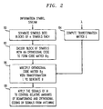
- FIG. 2 is a flowchart illustrating the process of producing antenna element signals in accordance with the principles of the invention.
-
- Beamforming and orthogonal space-time coding (such as space time transmit diversity (STTD) or a variant of STTD) are two methods being studied for transmission using, multiple antennas due to the potentially significant diversity and/or array gains that can be obtained. With beamforming, the signals transmitted by the different antennae differ only by a complex scaling factor, designed such that the signals add constructively at the intended receiver. With orthogonal space-time coding, the signals transmitted by the different antennae are orthogonal, in order to allow their independent demodulation.
- Beamforming and orthogonal coding are representative of two very different methods used for multiple antenna transmission. Beamforming relies completely on correct channel knowledge at the transmitter whereas orthogonal coding ignores any channel information the transmitter may have. In practice, the transmitter often has some instantaneous or average knowledge of the channel, in which case both these strategies are sub-optimal. A better transmission strategy as is here disclosed for the first time is to combine both orthogonal coding and beamforming in a proportion that is best suited for a particular transmission scenario.
- The new method here disclosed, which is an alternative to using only beamforming or orthogonal coding, is to combine beamforming with orthogonal coding in a proportion that depends on the amount of correct channel knowledge at the transmitter. To achieve this desired result, there is here disclosed a family of space-time block codes, for transmitting with two or more transmit antennas, that generate variations of the correlation between the signals transmitted by the different transmit antennas. Disclosed here are methods to encode and decode the signals, and the method to choose the appropriate correlations between the signals.
- Beamforming can be of two kinds: open-loop and closed-loop. In closed loop, which is also called closed-loop transmit diversity or maximal ratio transmission, there is a feedback channel from the receiver to the transmitter that provides instantaneous channel information to the multiple antenna transmitter. The channel information available to the transmitter may be corrupted due to channel estimation error, quantization errors, feedback errors and feedback delay (doppler). Use of pure beamforming in closed-loop systems (as is the usual practice) when channel information is not accurate can severely degrade performance. Such degradation is seen, for instance, in closed-loop systems at high mobile speeds. Pure orthogonal coding, which does not require channel knowledge at the transmitter, is never used in closed loop since that would waste available channel information.
- In open loop, there is no feedback from the receiver to the transmitter. Pure beamforming can be used with the help of spatial information gathered from the reverse link in a duplex system (e.g., for beamforming, angle of arrival measurement or channel correlation measurement from the reverse link is used). If the channels from all the transmit antennas are not well-correlated, beamforming provides little gain over orthogonal coding. For low channel correlations, orthogonal coding can even outperform open-loop beamforming.
- Both beamforming and orthogonal coding are instances of the general technique of space-time coding. In each of the above cases, it is clear that a space-time code that combines beamforming and orthogonal coding in an appropriate proportion will outperform each. To achieve this, there is here disclosed a new space-time block code that allows variation of the signal correlation matrix, which is comprised of the correlations between the signals transmitted by the different antennas. If the correlation between the signals transmitted from different antennae is chosen to be zero, it corresponds to orthogonal coding. If the magnitude of the normalized correlation between the signals is chosen to be 1, then it corresponds to pure beamforming. This allows the transmission to gracefully transition between beamforming and orthogonal coding by varying the desired correlation matrix, based on the amount of reliable channel knowledge the transmitter has at any time. Embodiments of the encoder and decoder here disclosed are modifications of an STTD encoder and decoder, respectively.
- In the reference "Combining transmit beamforming and orthogonal space-time coding by utilizing side information," by G. Jongren et al., in IEEE Sensor Array and Multichannel Signal Processing Workshop, pp. 153-157, 2000, there is proposed a scheme to combine beamforming and orthogonal space-time block codes using a different approach than that disclosed in this invention. In the Jongren et al reference, the code is parameterized by a complex matrix that minimizes pair-wise error probability of the code, and is computed using computationally intensive convex optimization via interior point methods. In contrast, in this invention, the block coding scheme is parameterized by one or more correlation coefficients that are determined using a look-up table from simple measurements made on the channel, as described in the description that follows. Also, the Jongren et al reference requires the complex matrix to be made known to the receiver, which is not required by the scheme proposed here.
- The description below is applied to a wireless digital communications system wherein the transmitter transmits a sequence of complex-valued information symbols via N transmit antennas. The information symbols represent voice, data or any other form of information that is required to be communicated to the wireless receiver. The signals transmitted from the N antennas are transformed by transmission channels that exist between the transmit antennas and the receiver. The transmission strategy of this invention is to encode the stream of information symbols to be transmitted into N streams of encoded symbols that are transmitted by the respective antenna elements. Such encoding is generally known as space-time coding, and the present invention specifies a particular encoding and decoding method that enables effective communication to take place when the transmitter has imperfect knowledge of the transmission channel.
- Referring to FIG. 1, there is illustrated a
wireless communication system 8 which can be used to implement an embodiment of the method of the invention having two transmit antennas (N=2). Thewireless communication system 8 includesbase transmitter 10 which transmits signals viaantennas 15, 18 tosubscriber unit 20. It is to be noted that, in FIG. 1, only the forward link of the communications system is shown where the system may also include a reverse link when there is duplex operation. A reverse link may also be required to provide a feedback loop for data and commands for operating the forward link in an adaptive array mode. - Referring to FIG. 2, in
step 80, the separate symbols of the stream of serial data oninput line 9 is formed into blocks of n symbols at the front end of space-time encoder 12. Thereafter, each block of symbols is encoded with an orthogonal code to form code matrix B0 in step 82 (see relationship (9)). Instep 84, the correlation coefficient λ is used to compute the transformation matrix L. It is to be noted that a single correlation coefficient λ will normally be used when there are more than two antennas. Instep 86 the orthogonal code matrix B0 is multiplied with the transformation L to obtain B. L is any matrix which satisfies the relationship - Stated in words, Φ is the desired correlation matrix and is equal to the conjugate transpose of L multiplied by L. In
step 88, the signals of B are applied to different antennae in space and time. - The
base transmitter 10 includestraffic channel 9 which is typically a serial data stream source of user data grouped into blocks of symbols each containing two symbols such as, for example, voice signals or data signals such as facsimile data, documents, software and the like. - The
traffic channel 8 is coupled to space-time encoder 12. The space-time encoder is coupled to receive complex-valued weights w1,w2,...,wN, which are shown in FIG. 1 for N=2 as w1 and w2. The beamformer weights are normalized to satisfy the equation - One or more correlation coefficients are fed to the space-
time encoder 12. In the embodiment with two transmit antennas (N=2), depicted in FIG. 1, there is a single correlation coefficient (λ) that is fed to the space-time encoder 12. The space-time encoder modifies and converts thetraffic channel 9 into N parallel traffic channels which are amplified by 22 and transmitted by the N transmit antennas, FIG. 1 shows the two output channels of the encoder, 18 and 20, when N=2. - The operation of the space-
time encoder 12 is now described. The encoder first encodes a block of M symbols to generate an orthogonal code matrix, whose column vectors are orthogonal to each other. A transformation matrix L is also generated where L is any solution of the equation LHL = Φ, where Φ is the desired correlation matrix of the multiple antenna signals with N rows and N columns. Stated differently, the transformation matrix L is a matrix such that, when the conjugate transpose of L is multiplied by L a desired correlation matrix Φ is generated. The element in the ith row and jth column of the correlation matrix Φ is the desired correlation of the signal transmitted by the ith antenna with the signal transmitted by the jth antenna. Multiplication of the matrix
- This procedure is better explained by describing the embodiment shown in FIG. 1 for N=2 transmit antennas. In this embodiment, the block length M is also equal to 2, and the orthogonal code

- The signal correlation matrix Φ is defined in terms of the correlation coefficient λ and beamformer weights w1 and w2 asThe final code matrix is designed as
 where L is the transformation matrix, which is any of the several possible solutions to the equation LHL = Φ. Any of these solutions can be used in designing the transformation matrix L. One such solution is given by

- For this embodiment of the transformation matrix L, the space-
time encoder 12 applies the signals to the two antennas in the two time intervals according to Table 1. The same encoding procedure is applied to the next block of two symbols, and so forth.Time 1 Time 2 Antenna 1 Antenna 2 - A different solution of the equation LHL = Φ yields a different relationship for L and consequently a space-time code that is different from the embodiment described above. An example of such a code is when L is the matrix square root solution, which yields a matrix L such that LH = L and is given byThis choice of L results in an encoder that applies the signals given in Table 2. These or other solutions of LHL = Φ can be used to design the encoder.

Time 1 Time 2 Antenna 1 Antenna 2 - The transmission scheme described above combines the strategies of beamforming and orthogonal coding. The code correlation coefficient λ is a coefficient that can be used by the transmitter to control the relative amounts of beamforming and orthogonal coding that are applied. When λ = 0, then the above embodiment of the transmission scheme with n=2 is similar to orthogonal coding using a modified Alamouti code. (See "A simple transmitter diversity scheme for wireless communications," by S. Alamouti, IEEE Journal on Selected Areas in Communications, pp. 1451-1458, October 1998; and "Transmitter diversity technique for wireless communications," U.S. Patent No. 6,185,258B1, by S. Alamouti and Tarokh. When λ =1, then the transmission scheme is similar to beamforming. Smaller values of the code correlation coefficient λ means that the transmission scheme includes both beamforming and orthogonal coding but is weighted toward orthogonal coding, and larger values of λ means that the transmission scheme includes both beamforming and orthogonal coding but is weighted toward beamforming. A large value of λ should be chosen when confidence is high at the transmitter on the correctness of the beamformer weights (W1 and W2 in the embodiment described above). The beamformer weights in turn depend on the knowledge that the transmitter has about the channel. A small value of λ should be chosen when there is little confidence at the transmitter about the correctness of the beamformer weights. For instance, in a closed loop transmit diversity system in mobile communications, λ could be made to be close to 1 when the mobile speed is low and there is reliable feedback of beamforming weights from the mobile receiver to the transmitter. At high mobile speeds when the feedback information is not reliable, λ can be made to be close to 0 so that orthogonal coding is implemented, which does not rely on feedback information. The code correlation coefficient can be optimally selected for any given communications scenario. An example of optimal design of λ is to minimize the probability of symbol or bit error at the receiver subject to a constraint on the transmit power. Another possible method of selecting an optimal λ is to minimize the transmit power subject to a constraint on the probability of error at the receiver.
- The
correlation parameter selector 14 of Fig. 1 determines the value of λ in an open-loop downlink system having at least two antennae. Initially, measurements of the uplink channel are made at the downlink multiple antenna transmitter using one of the known channel estimation schemes such as, for example, the pilot signals on the uplink. The measurements obtained are used to determine the correlation coefficient ρ between the channels received by the two antennae. The transmitter then selects a value of λ from a look up table. The look up table contains a list of the optimal values of λ for each value of the channel correlation coefficient ρ and is created and stored at the transmitter prior to the intended communication. The table can be designed to minimize bit or frame error rate for a given power constraint, or to minimize transmit power to achieve a bit or frame error rate requirement. - The encoded symbols are transmitted over the transmit antennas after multiplication with spreading code (if any) and frequency up-shifting by a carrier signal in 22. Assuming frequency non-selective fading channels between the transmit 24, 26 and receive 28 antennae, the signal received from a particular transmitter antenna is the signal transmitted by the antenna multiplied by a complex channel gain. For example, where N=2, the channel gains from the first and second transmitter antennae are denoted as h1 and h2, respectively. The block of encoded symbols at times 1 and 2, as described above, are received, after despreading as baseband signal vector r, where

- In the above relationship, h = [h1 h2]T and is the channel gain vector (which includes transmitted signal amplitude), n = [n1 n2]T and is the noise vector, and B0 is the orthogonal code matrix described above.
- Equation (7) for the received signal can be rearranged and written aswhere L is the transformation matrix applied at the transmitter, as described above. It is clear from the above model for the received signal that, to the receiver, the received signal appears to be coming from a multiple antenna transmitter that transmits orthogonal signals using the orthogonal hλ. Therefore, the receiver that is used to demodulate signals transmitted using the orthogonal code B0 can also be used to demodulate the signals transmitted using the proposed space time code, by replacing the true channel estimates with estimates of the virtual channel. Since the embodiment shown in Figure 1 uses the STTD orthogonal code, the

receiver 30 is comprised of theSTTD decoder 24 in conjunction with avirtual channel estimator 23 which computes estimates of the virtual channel hλ from the received signal. - In one embodiment of the
virtual channel estimator 23, the dedicated pilot symbols, which are symbols known at the receiver that are embedded into the transmitted information symbols and are also encoded using the same code, are used. If the dedicated pilot symbols are encoded this way, the known method of estimating the channel using a pilot for the STTD code directly yields the required estimate of the virtual channel vector. - Another embodiment of 23 to estimate the virtual channel is to estimate the true channel h using any of the methods commonly used for channel estimation, and estimate the code coefficient λ, and use these two estimates to compute an estimate of the virtual channel by using the relation hλ = Lh. In this embodiment, the true channel estimation can be reliably performed using the common pilot symbols that are not encoded with the proposed code. The value of λ can either be explicitly signalled to the receiver by the transmitter via the forward data link, or can be estimated at the receiver by using, for example, the dedicated pilot on the downlink. Estimation of λ at the receiver can be performed using the same look-up table method used in the
correlation coefficient selector 14, along with estimation of the channel coefficients at the receiver, both in open and closed loop. The computation of λ in this embodiment is therefore performed in a manner identical to the selection of λ at the transmitter by 14, except that no adjustment of time delay needs to be made at the receiver in closed loop. - The proposed transmission technique can also be used in conjunction with multiple antennae at the receiver, in a manner similar to the multiple antenna reception of orthogonal coded signals.
- Having a control on the amount of beamforming and orthogonal coding is useful in the special case of scheduled transmission for high speed data. In scheduled transmissions, the transmitter transmits a burst of data at a high data rate during the times when it estimates that the channel gain is large. It is beneficial in this case to perform more beamforming than orthogonal coding. Therefore, one method to improve scheduled transmission is to select a larger value of λ during these bursts of high data rate transmission than the λ that would be chosen for non-scheduled transmission.
- While various embodiments of the invention have been described, it should be apparent that variations and alternative embodiments can be implemented in accordance with the invention. It is to be understood, therefore, that the invention is not to be in any way limited except in accordance with the spirit of the appended claims and their equivalents.
Claims (10)
- A method of transmitting signals from at least two antennae comprising the steps of:detemining a degree of difference between received signals from at least two antennae; andusing the degree of difference to select between orthogonal coding andbeamforming for transmitting signals using the at least two antennae.
- The method of Claim 1, wherein the step of determining a degree of difference between the received signals comprises determining a degree of amplitude difference.
- The method of Claim 1, wherein the step of determining a degree of difference between the received signals comprises determining a degree of phase difference.
- The method of Claims 1 or 2 or 3, wherein the step of determining a degree of difference comprises determining a degree of correlation between received signals.
- The method of Claims 1 or 2 or 3 or 4, wherein the step of using the degree of difference comprises using the degree of difference to select a proportion of orthogonal coding relative to a proportion beamforming of the transmitting signal.
- The method of Claims 1 or 2 or 3 or 4 or 5, wherein the degree of difference varies between a first level and a second level, the first level results in selecting beamforming for transmitting and the second level results in selecting orthogonal coding for transmitting.
- The method of Claims 1 or 2 or 3 or 4 or 5, wherein the degree of difference varies between a first level and a second level, the degree of difference between the first and second levels results in selecting both beamforming and orthogonal coding for transmitting.
- The method of Claims 1 or 2 or 3 or 4 or 5, wherein the degree of difference varies between a first level and a second level, the degree of difference results in transmitting more beamforming than orthogonal coding if the degree of difference is closer to the first level.
- The method of Claims 1 or 2 or 3 or 4 or 5, wherein the degree of difference varies between a first level and a second level, the degree of difference results in transmitting more orthogonal coding than beamforming if the degree of difference is closer to the second level.
- The method of Claim 1 or 2 or 3 or 4 or 5, wherein the degree of difference varies between a first level and a second level, the degree of difference relative to the first and second levels determines the amount of beamforming relative to orthogonal coding used for transmitting.
Applications Claiming Priority (2)
| Application Number | Priority Date | Filing Date | Title |
|---|---|---|---|
| US09/873,706 US7499499B2 (en) | 2001-06-04 | 2001-06-04 | Method for multiple antenna transmission |
| US873706 | 2001-06-04 |
Publications (3)
| Publication Number | Publication Date |
|---|---|
| EP1265376A2 true EP1265376A2 (en) | 2002-12-11 |
| EP1265376A3 EP1265376A3 (en) | 2003-12-17 |
| EP1265376B1 EP1265376B1 (en) | 2005-01-19 |
Family
ID=25362168
Family Applications (1)
| Application Number | Title | Priority Date | Filing Date |
|---|---|---|---|
| EP01309540A Expired - Lifetime EP1265376B1 (en) | 2001-06-04 | 2001-11-12 | Method for multiple antenna transmission |
Country Status (4)
| Country | Link |
|---|---|
| US (1) | US7499499B2 (en) |
| EP (1) | EP1265376B1 (en) |
| JP (1) | JP2003069461A (en) |
| DE (1) | DE60108481T2 (en) |
Cited By (8)
| Publication number | Priority date | Publication date | Assignee | Title |
|---|---|---|---|---|
| EP1367760A2 (en) * | 2002-05-27 | 2003-12-03 | Nokia Corporation | Transmit/receive diversity wireless communication |
| WO2004056029A2 (en) * | 2002-12-16 | 2004-07-01 | Nortel Networks Limited | Communication system with uplink space-time coding via coordinated mobile terminals |
| EP1634387A2 (en) * | 2003-06-09 | 2006-03-15 | Cognio, Inc. | Compensation techniques for group delay effects in transmit beamforming |
| WO2007094786A1 (en) * | 2006-02-16 | 2007-08-23 | Lucent Technologies Inc. | Method of multiple-antenna communication having improved utilization of channel correlations |
| EP1851891A2 (en) * | 2004-11-30 | 2007-11-07 | The Regents of the University of California | Method and apparatus for an adaptive multiple-input multiple-output (mimo) wireless communications systems |
| WO2010059780A2 (en) * | 2008-11-19 | 2010-05-27 | Harris Corporation | Code division multiple access based contingency transmission |
| US7773685B2 (en) | 2002-05-27 | 2010-08-10 | Nokia Corporation | Transmitting and receiving methods |
| US8477864B2 (en) * | 2008-08-14 | 2013-07-02 | Alcatel Lucent | Method of multiple-antenna communication having improved utilization of channel correlations |
Families Citing this family (14)
| Publication number | Priority date | Publication date | Assignee | Title |
|---|---|---|---|---|
| KR100615888B1 (en) * | 2001-08-25 | 2006-08-25 | 삼성전자주식회사 | Mobile communication apparatus and method including antenna array |
| US7103325B1 (en) * | 2002-04-05 | 2006-09-05 | Nortel Networks Limited | Adaptive modulation and coding |
| US7010055B2 (en) * | 2002-06-27 | 2006-03-07 | Motorola, Inc. | System implementing closed loop transmit diversity and method thereof |
| US7039369B2 (en) * | 2003-10-31 | 2006-05-02 | Mitsubishi Electric Research Laboratories, Inc. | Transmit diversity gain for wireless communications networks |
| US7680212B2 (en) * | 2004-08-17 | 2010-03-16 | The Board Of Trustees Of The Leland Stanford Junior University | Linear precoding for multi-input systems based on channel estimate and channel statistics |
| CN101023602B (en) * | 2004-09-17 | 2012-12-19 | 株式会社Ntt都科摩 | Mobile communication method, mobile station and base station |
| WO2006068413A1 (en) * | 2004-12-21 | 2006-06-29 | Electronics And Telecommunications Research Institute | Method for selecting switched beam using pilot signal and system thereof |
| US7894402B2 (en) * | 2005-04-15 | 2011-02-22 | Alcatel-Lucent Usa Inc. | High rate packet data spatial division multiple access (SDMA) |
| CN1870461B (en) * | 2005-05-24 | 2011-06-01 | 都科摩(北京)通信技术研究中心有限公司 | MIMO system based on random emitting beam formed and its user scheduling method |
| JP4708910B2 (en) * | 2005-08-09 | 2011-06-22 | 株式会社エヌ・ティ・ティ・ドコモ | Mobile communication system control method, control apparatus, and mobile communication system |
| US7787819B2 (en) * | 2006-08-25 | 2010-08-31 | Space Systems / Loral, Inc. | Ground-based beamforming for satellite communications systems |
| US8514693B2 (en) * | 2008-07-11 | 2013-08-20 | Alcatel Lucent | Broadcast and multicast in single frequency networks using othrogonal space-time codes |
| CN102571173B (en) * | 2010-12-30 | 2014-08-13 | 联芯科技有限公司 | Method for terminal to select transmission antennae in open loop mode, device and mobile terminal |
| US8891689B2 (en) * | 2012-03-23 | 2014-11-18 | Mediatek Singapore Pte. Ltd. | Demodulating data streams |
Citations (2)
| Publication number | Priority date | Publication date | Assignee | Title |
|---|---|---|---|---|
| EP1073212A2 (en) * | 1999-05-28 | 2001-01-31 | Texas Instruments Incorporated | Wireless system with transmitter with multiple antennas and combining open loop and closed loop transmit diversity |
| WO2001069800A2 (en) * | 2000-03-14 | 2001-09-20 | Telefonaktiebolaget Lm Ericsson (Publ) | Robust utilization of feedback information in space-time coding |
Family Cites Families (10)
| Publication number | Priority date | Publication date | Assignee | Title |
|---|---|---|---|---|
| US6173014B1 (en) * | 1994-08-02 | 2001-01-09 | Telefonaktiebolaget Lm Ericsson | Method of and apparatus for interference rejection combining and downlink beamforming in a cellular radio communications system |
| US6167286A (en) * | 1997-06-05 | 2000-12-26 | Nortel Networks Corporation | Multi-beam antenna system for cellular radio base stations |
| US6185258B1 (en) * | 1997-09-16 | 2001-02-06 | At&T Wireless Services Inc. | Transmitter diversity technique for wireless communications |
| US6178196B1 (en) * | 1997-10-06 | 2001-01-23 | At&T Corp. | Combined interference cancellation and maximum likelihood decoding of space-time block codes |
| US6088408A (en) * | 1998-11-06 | 2000-07-11 | At & T Corp. | Decoding for generalized orthogonal designs for space-time codes for wireless communication |
| US6154485A (en) * | 1998-10-19 | 2000-11-28 | Motorola, Inc. | Receiver in a wireless communications system for receiving signals having combined orthogonal transmit diversity and adaptive array techniques |
| US6587515B1 (en) * | 1999-02-10 | 2003-07-01 | Hamid Jafarkhani | Differential transmitter diversity technique for wireless communications |
| ES2224667T3 (en) * | 1999-05-19 | 2005-03-01 | Nokia Corporation | METHOD AND SYSTEM OF DIVERSITY OF TRANSMISSION. |
| US6546026B1 (en) * | 1999-06-17 | 2003-04-08 | Lucent Technologies Inc. | Multi-diversity synchronization technique for improving synchronization performance in wireless applications over fading channels |
| US6317410B1 (en) * | 1999-09-13 | 2001-11-13 | Lucent Technologies Inc. | Receiver architecture employing space time spreading and orthogonal transmit diversity techniques |
-
2001
- 2001-06-04 US US09/873,706 patent/US7499499B2/en active Active
- 2001-11-12 DE DE60108481T patent/DE60108481T2/en not_active Expired - Lifetime
- 2001-11-12 EP EP01309540A patent/EP1265376B1/en not_active Expired - Lifetime
-
2002
- 2002-06-04 JP JP2002162231A patent/JP2003069461A/en active Pending
Patent Citations (2)
| Publication number | Priority date | Publication date | Assignee | Title |
|---|---|---|---|---|
| EP1073212A2 (en) * | 1999-05-28 | 2001-01-31 | Texas Instruments Incorporated | Wireless system with transmitter with multiple antennas and combining open loop and closed loop transmit diversity |
| WO2001069800A2 (en) * | 2000-03-14 | 2001-09-20 | Telefonaktiebolaget Lm Ericsson (Publ) | Robust utilization of feedback information in space-time coding |
Non-Patent Citations (1)
| Title |
|---|
| JOENGREN G ET AL: "UTILIZING QUANTIZED FEEDBACK INFORMATION IN ORTHOGONAL SPACE-TIME BLOCK CODING" GLOBECOM'00. 2000 IEEE GLOBAL TELECOMMUNICATIONS CONFERENCE. SAN FRANCISCO, CA, NOV. 27 - DEC. 1, 2000, IEEE GLOBAL TELECOMMUNICATIONS CONFERENCE, NEW YORK, NY: IEEE, US, vol. 2 OF 4, 27 November 2000 (2000-11-27), pages 995-999, XP001017234 ISBN: 0-7803-6452-X * |
Cited By (20)
| Publication number | Priority date | Publication date | Assignee | Title |
|---|---|---|---|---|
| EP1367760A2 (en) * | 2002-05-27 | 2003-12-03 | Nokia Corporation | Transmit/receive diversity wireless communication |
| EP1367760A3 (en) * | 2002-05-27 | 2004-04-14 | Nokia Corporation | Transmit/receive diversity wireless communication |
| US7773685B2 (en) | 2002-05-27 | 2010-08-10 | Nokia Corporation | Transmitting and receiving methods |
| US7508798B2 (en) | 2002-12-16 | 2009-03-24 | Nortel Networks Limited | Virtual mimo communication system |
| WO2004056029A3 (en) * | 2002-12-16 | 2004-08-26 | Nortel Networks Ltd | Communication system with uplink space-time coding via coordinated mobile terminals |
| EP1890415A2 (en) * | 2002-12-16 | 2008-02-20 | Nortel Networks Limited | Communication System with Uplink Space-Time Coding via Coordinated Mobile Terminals |
| EP1890415A3 (en) * | 2002-12-16 | 2008-08-20 | Nortel Networks Limited | Communication System with Uplink Space-Time Coding via Coordinated Mobile Terminals |
| EP2365656A1 (en) * | 2002-12-16 | 2011-09-14 | Nortel Networks Limited | Virtual MIMO communication system |
| WO2004056029A2 (en) * | 2002-12-16 | 2004-07-01 | Nortel Networks Limited | Communication system with uplink space-time coding via coordinated mobile terminals |
| KR101033104B1 (en) * | 2002-12-16 | 2011-05-06 | 노오텔 네트웍스 리미티드 | Communication system with uplink space-time coding via coordinated mobile terminals |
| EP2363969A1 (en) * | 2002-12-16 | 2011-09-07 | Nortel Networks Limited | Communication system with uplink space-time coding via coordinated mobile terminals |
| EP1634387A2 (en) * | 2003-06-09 | 2006-03-15 | Cognio, Inc. | Compensation techniques for group delay effects in transmit beamforming |
| EP1634387A4 (en) * | 2003-06-09 | 2011-11-02 | Ipr Licensing Inc | Compensation techniques for group delay effects in transmit beamforming |
| EP1851891A2 (en) * | 2004-11-30 | 2007-11-07 | The Regents of the University of California | Method and apparatus for an adaptive multiple-input multiple-output (mimo) wireless communications systems |
| EP1851891A4 (en) * | 2004-11-30 | 2012-08-08 | Univ California | Method and apparatus for an adaptive multiple-input multiple-output (mimo) wireless communications systems |
| WO2007094786A1 (en) * | 2006-02-16 | 2007-08-23 | Lucent Technologies Inc. | Method of multiple-antenna communication having improved utilization of channel correlations |
| US8477864B2 (en) * | 2008-08-14 | 2013-07-02 | Alcatel Lucent | Method of multiple-antenna communication having improved utilization of channel correlations |
| WO2010059780A3 (en) * | 2008-11-19 | 2010-07-08 | Harris Corporation | Code division multiple access based contingency transmission |
| US8169886B2 (en) | 2008-11-19 | 2012-05-01 | Harris Corporation | Code division multiple access based contingency transmission |
| WO2010059780A2 (en) * | 2008-11-19 | 2010-05-27 | Harris Corporation | Code division multiple access based contingency transmission |
Also Published As
| Publication number | Publication date |
|---|---|
| US20020186779A1 (en) | 2002-12-12 |
| EP1265376A3 (en) | 2003-12-17 |
| DE60108481T2 (en) | 2006-01-12 |
| EP1265376B1 (en) | 2005-01-19 |
| DE60108481D1 (en) | 2005-02-24 |
| JP2003069461A (en) | 2003-03-07 |
| US7499499B2 (en) | 2009-03-03 |
Similar Documents
| Publication | Publication Date | Title |
|---|---|---|
| US8675772B2 (en) | Method for multiple antenna transmission using partial channel knowledge | |
| EP1265376B1 (en) | Method for multiple antenna transmission | |
| JP4574258B2 (en) | Method and apparatus for transmitting signal compensated for channel fluctuation in multi-antenna mobile communication system | |
| CN100375419C (en) | Dynamic power control for space time diversity transmit antenna pairs | |
| EP1366579B1 (en) | Method for controlling the weighting of a data signal in the at least two antenna elements of a radio connection unit, module and communications system | |
| US7697625B2 (en) | Method and system for transmitting and receiving data streams | |
| USRE42681E1 (en) | Wireless system with transmitter having multiple transmit antennas and combining open loop and closed loop transmit diversities | |
| US6892059B1 (en) | Closed-loop transmitting antenna diversity method, base station apparatus and mobile station apparatus therefor, in a next generation mobile telecommunications system | |
| US7447270B1 (en) | Method for controlling the data signal weighting in multi-element transceivers and corresponding devices and telecommunications network | |
| US8059771B2 (en) | Method and system for transmitting and receiving data streams | |
| US20050213682A1 (en) | Apparatus and method for transmitting and receiving data in a mobile communication system using an array antenna | |
| KR101045454B1 (en) | Wireless communication system using multiantenna transmission technique, and multi-user scheduler applied thereto | |
| US8009754B2 (en) | Wireless communication method, radio receiving apparatus, radio transmitting apparatus, and wireless communication system | |
| US20040032910A1 (en) | MIMO systems with STTD encoding and dynamic power allocation | |
| US20020000948A1 (en) | Semi-blind transmit antenna array device using feedback information and method thereof in a mobile communication system | |
| KR20050120441A (en) | Transmission diversity apparatus and method using multiple antenna in a mobile communication system | |
| US20080089432A1 (en) | Apparatus and method for beamforming in a multiple-input multiple-output system | |
| EP1289169B1 (en) | Mobile communication apparatus including antenna array and mobile communication method | |
| JP4485530B2 (en) | Method and apparatus for wireless communication | |
| Catreux et al. | Enhanced capacity using transmit diversity and smart antennas |
Legal Events
| Date | Code | Title | Description |
|---|---|---|---|
| PUAI | Public reference made under article 153(3) epc to a published international application that has entered the european phase |
Free format text: ORIGINAL CODE: 0009012 |
|
| 17P | Request for examination filed |
Effective date: 20011121 |
|
| AK | Designated contracting states |
Kind code of ref document: A2 Designated state(s): AT BE CH CY DE DK ES FI FR GB GR IE IT LI LU MC NL PT SE TR |
|
| AX | Request for extension of the european patent |
Free format text: AL;LT;LV;MK;RO;SI |
|
| PUAL | Search report despatched |
Free format text: ORIGINAL CODE: 0009013 |
|
| AK | Designated contracting states |
Kind code of ref document: A3 Designated state(s): AT BE CH CY DE DK ES FI FR GB GR IE IT LI LU MC NL PT SE TR |
|
| AX | Request for extension of the european patent |
Extension state: AL LT LV MK RO SI |
|
| RIC1 | Information provided on ipc code assigned before grant |
Ipc: 7H 04B 7/06 A Ipc: 7H 04L 1/06 B Ipc: 7H 04L 1/00 B |
|
| 17Q | First examination report despatched |
Effective date: 20040223 |
|
| GRAP | Despatch of communication of intention to grant a patent |
Free format text: ORIGINAL CODE: EPIDOSNIGR1 |
|
| AKX | Designation fees paid |
Designated state(s): DE FR GB IT |
|
| GRAS | Grant fee paid |
Free format text: ORIGINAL CODE: EPIDOSNIGR3 |
|
| GRAA | (expected) grant |
Free format text: ORIGINAL CODE: 0009210 |
|
| AK | Designated contracting states |
Kind code of ref document: B1 Designated state(s): DE FR GB IT |
|
| PG25 | Lapsed in a contracting state [announced via postgrant information from national office to epo] |
Ref country code: IT Free format text: LAPSE BECAUSE OF FAILURE TO SUBMIT A TRANSLATION OF THE DESCRIPTION OR TO PAY THE FEE WITHIN THE PRESCRIBED TIME-LIMIT;WARNING: LAPSES OF ITALIAN PATENTS WITH EFFECTIVE DATE BEFORE 2007 MAY HAVE OCCURRED AT ANY TIME BEFORE 2007. THE CORRECT EFFECTIVE DATE MAY BE DIFFERENT FROM THE ONE RECORDED. Effective date: 20050119 |
|
| REG | Reference to a national code |
Ref country code: GB Ref legal event code: FG4D |
|
| REG | Reference to a national code |
Ref country code: IE Ref legal event code: FG4D |
|
| REF | Corresponds to: |
Ref document number: 60108481 Country of ref document: DE Date of ref document: 20050224 Kind code of ref document: P |
|
| PLBE | No opposition filed within time limit |
Free format text: ORIGINAL CODE: 0009261 |
|
| STAA | Information on the status of an ep patent application or granted ep patent |
Free format text: STATUS: NO OPPOSITION FILED WITHIN TIME LIMIT |
|
| ET | Fr: translation filed | ||
| 26N | No opposition filed |
Effective date: 20051020 |
|
| REG | Reference to a national code |
Ref country code: FR Ref legal event code: CD Owner name: ALCATEL-LUCENT USA INC. Effective date: 20131122 |
|
| REG | Reference to a national code |
Ref country code: FR Ref legal event code: GC Effective date: 20140410 |
|
| REG | Reference to a national code |
Ref country code: FR Ref legal event code: RG Effective date: 20141015 |
|
| REG | Reference to a national code |
Ref country code: FR Ref legal event code: PLFP Year of fee payment: 15 |
|
| REG | Reference to a national code |
Ref country code: FR Ref legal event code: PLFP Year of fee payment: 16 |
|
| PGFP | Annual fee paid to national office [announced via postgrant information from national office to epo] |
Ref country code: GB Payment date: 20161122 Year of fee payment: 16 |
|
| REG | Reference to a national code |
Ref country code: FR Ref legal event code: PLFP Year of fee payment: 17 |
|
| GBPC | Gb: european patent ceased through non-payment of renewal fee |
Effective date: 20171112 |
|
| PGFP | Annual fee paid to national office [announced via postgrant information from national office to epo] |
Ref country code: DE Payment date: 20180601 Year of fee payment: 17 |
|
| PGFP | Annual fee paid to national office [announced via postgrant information from national office to epo] |
Ref country code: FR Payment date: 20180530 Year of fee payment: 17 |
|
| PG25 | Lapsed in a contracting state [announced via postgrant information from national office to epo] |
Ref country code: GB Free format text: LAPSE BECAUSE OF NON-PAYMENT OF DUE FEES Effective date: 20171112 |
|
| REG | Reference to a national code |
Ref country code: DE Ref legal event code: R119 Ref document number: 60108481 Country of ref document: DE |
|
| PG25 | Lapsed in a contracting state [announced via postgrant information from national office to epo] |
Ref country code: DE Free format text: LAPSE BECAUSE OF NON-PAYMENT OF DUE FEES Effective date: 20190601 Ref country code: FR Free format text: LAPSE BECAUSE OF NON-PAYMENT OF DUE FEES Effective date: 20181130 |
|
| REG | Reference to a national code |
Ref country code: DE Ref legal event code: R081 Ref document number: 60108481 Country of ref document: DE Owner name: WSOU INVESTMENTS, LLC, LOS ANGELES, US Free format text: FORMER OWNER: LUCENT TECHNOLOGIES INC., MURRAY HILL, N.J., US |