EP1265357A1 - Driver circuit - Google Patents
Driver circuit Download PDFInfo
- Publication number
- EP1265357A1 EP1265357A1 EP01305015A EP01305015A EP1265357A1 EP 1265357 A1 EP1265357 A1 EP 1265357A1 EP 01305015 A EP01305015 A EP 01305015A EP 01305015 A EP01305015 A EP 01305015A EP 1265357 A1 EP1265357 A1 EP 1265357A1
- Authority
- EP
- European Patent Office
- Prior art keywords
- transistor
- coupled
- driver circuit
- impedance
- resonances
- Prior art date
- Legal status (The legal status is an assumption and is not a legal conclusion. Google has not performed a legal analysis and makes no representation as to the accuracy of the status listed.)
- Granted
Links
- 230000000694 effects Effects 0.000 claims abstract description 19
- 238000000034 method Methods 0.000 claims description 10
- 230000000116 mitigating effect Effects 0.000 claims description 7
- 238000001914 filtration Methods 0.000 claims description 6
- 230000008878 coupling Effects 0.000 claims description 2
- 238000010168 coupling process Methods 0.000 claims description 2
- 238000005859 coupling reaction Methods 0.000 claims description 2
- 230000001939 inductive effect Effects 0.000 claims description 2
- 238000010586 diagram Methods 0.000 description 12
- 230000004044 response Effects 0.000 description 10
- 239000003990 capacitor Substances 0.000 description 8
- 238000004519 manufacturing process Methods 0.000 description 2
- 230000002411 adverse Effects 0.000 description 1
- 230000000903 blocking effect Effects 0.000 description 1
- 238000012986 modification Methods 0.000 description 1
- 230000004048 modification Effects 0.000 description 1
- 230000003287 optical effect Effects 0.000 description 1
Images


Classifications
-
- H—ELECTRICITY
- H01—ELECTRIC ELEMENTS
- H01S—DEVICES USING THE PROCESS OF LIGHT AMPLIFICATION BY STIMULATED EMISSION OF RADIATION [LASER] TO AMPLIFY OR GENERATE LIGHT; DEVICES USING STIMULATED EMISSION OF ELECTROMAGNETIC RADIATION IN WAVE RANGES OTHER THAN OPTICAL
- H01S5/00—Semiconductor lasers
- H01S5/04—Processes or apparatus for excitation, e.g. pumping, e.g. by electron beams
- H01S5/042—Electrical excitation ; Circuits therefor
Definitions
- the invention relates, in general, to driver circuits and more particularly to laser driver circuits, such as those used in telecommunications applications, especially, for high speed optical communications.
- a laser driver circuit is used for modulating the light output of a laser diode at high frequencies in accordance with data applied to the driver circuit.
- the laser driver circuit is usually based on a balanced differential pair with a differential data input being applied to the differential pair.
- a first aspect of the present invention provides a driver circuit comprising a first transistor having a first current electrode coupled to a current source, a second current electrode and a control electrode coupled to a first input terminal, a low impedance load having a first terminal coupled to the second current electrode of the first transistor and a second terminal coupled to a supply rail, and an impedance element coupled to the control electrode of the first transistor to provide AC feedback thereto.
- the first transistor forms part of a differential pair in which a second transistor has a first current electrode coupled to the current source, a second current electrode coupled to a resistive element and a control electrode coupled to a second input terminal, the first and second input terminals being differential inputs for receiving differential data signals.
- the impedance element preferably has a first terminal coupled to the control electrode of the first transistor and a second terminal coupled to the second current electrode of one of the first or second transistors.
- the driver circuit further comprises a second impedance element having a first terminal coupled to the control electrode of the second transistor and a second terminal coupled to the second current electrode of the second transistor.
- the impedance element comprises a differential amplifier having an input coupled to the second current electrode of one of the first or second transistors and a first and second differential outputs, the first differential output being coupled to the control electrode of the first transistor and the second differential output being coupled to the control electrode of the second transistor.
- the impedance element comprises a resistive element and a capacitive element coupled in series between the second current electrode of the first transistor and the control electrode of the first transistor.
- the impedance element can include an inductive element.
- the low impedance load is a laser diode.
- a method of mitigating for the effects of resonances in a driver circuit having a high impedance source and a low impedance load comprising coupling an impedance feedback path between an input to the low impedance load and an input to the high impedance source.
- the low impedance load is a laser diode.
- the high impedance source is preferably a first transistor forming part of a differential pair.
- the impedance feedback path is a resistive element and a capacitive element coupled in series.
- the values of the resistive element and the capacitive element can be chosen so as to provide a low pass filtering effect having a cut-off frequency less than a lowest frequency of any substantial resonances present.
- the values of the resistive element and the capacitive element can be chosen so as to provide a filtering effect reducing output power including any resonances present but maintaining a high bandwidth.
- FIG.1 shows a known laser driver circuit 100, essentially having a differential pair configuration.
- a resistor 104 is coupled to a positive supply voltage rail 102. Also coupled to the supply voltage rail 102 is a laser diode 106.
- the resistor 104 is connected in series with a collector electrode of a first transistor 108.
- An emitter electrode of the first transistor 108 is coupled to a current source 112.
- an emitter electrode of a second transistor 110 is coupled to the current source 112.
- a first signal input lead 116 is coupled to a base electrode of the first transistor 108 and a second signal input lead 118 is coupled to a base electrode of the second transistor 110.
- a high frequency input data signal is applied to the second signal input lead 118 and an inverse input data signal is applied to the first signal input lead 116.
- the first transistor 108 and the second transistor 110 are matched.
- the resistor 104 functions as a means of power dissipation and approximate load matching.
- an impedance mismatch occurs because the sources of the laser driver circuit 100 are first transistor 108 and second transistor 110 of approximate resistance 1k ⁇ , whereas the loads of the circuit are laser diode 106 having equivalent AC resistance of approximately 5 ⁇ and resistor 104 having resistance of typically 30 ⁇ .
- FIG.2 An example frequency response curve for the laser driver circuit 100 of FIG.1 is illustrated in FIG.2. At relatively lower frequencies the output response 200 maintains a constant value 202 with respect to the input frequency. At high frequencies, resonances 204 are evident which would have a substantial effect on an output signal.
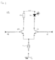
- FIG.3 A circuit diagram of a first embodiment of the present invention is illustrated in FIG.3.
- the structure of the circuit diagram 300 is the same as that of the circuit diagram shown in FIG.1, with identical features to those of FIG.1 having the same reference numerals as those of FIG.1, but with the prefix "3" instead of the prefix "1".
- resistor 104 in FIG.1 is resistor 304 in FIG.3.
- a feedback impedance 320 is coupled between the collector electrode of the second transistor 310 and the second signal input lead 318.
- the feedback impedance 320 generally comprises a resistor and a capacitor.
- the addition of the feedback impedance 320 acts to feed back the reflected signals from the laser diode 306 and transistor 310 into the second signal input lead 318.
- the magnitude of the resistor and the capacitor within feedback impedance 320 affect the frequency response of the circuit.
- the feedback impedance 320 can mitigate the resonances.
- an optional feedback impedance 322 (indicated by a dotted line in FIG.3) is coupled between the collector electrode of the first transistor 308 and the first signal input lead 316.
- the optional feedback impedance 322 generally comprising a resistor and a capacitor, assists in maintaining the laser driver circuit 300 in a balanced state.
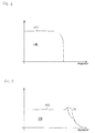
- FIG.4 An example frequency response curve of the laser driver circuit 300 of FIG.3 is illustrated in FIG.4 and in FIG.5.
- the frequency response curve 400 of FIG. 4 results when the resistor and the capacitor of the feedback impedance 320 have relatively low values (for example 600 ⁇ and 5pF, respectively).
- the resistor and capacitor serve to provide a low pass filter with a cut-off frequency determined to be just lower than the resonance frequency.
- the output 400 maintains a constant value 402.
- the output 400 is however cut-off before the very high frequency range (and associated resonances) are reached. Thus, although the bandwidth is reduced, the output power is maintained at lower frequencies.
- the frequency response curve 500 of FIG. 5 results when the resistor and the capacitor of the feedback impedance 320 have relatively high values (for example 2k ⁇ and 20pF, respectively). Again, at lower frequencies the output 500 maintains a constant value 502. However, the output power is somewhat reduced at lower frequencies due to the effect of the feedback impedance. This filtering effect also causes the resonances to be substantially reduced, as shown at resonance peaks 504.
- the feedback impedance would have a very high value capacitor and a low value resistor to provide essentially DC blocking with a flat frequency response.
- the realisation of a very high value capacitor within an integrated circuit causes manufacturing difficulties.
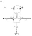
- FIG.6 A circuit diagram of a second embodiment of the present invention is illustrated in FIG.6.
- the structure of the circuit diagram 600 is the same as that of the circuit diagram shown in FIG.1, with identical features to those of FIG.1 having the same reference numerals as those of FIG.1, but with the prefix "6" instead of the prefix "1".
- resistor 104 in FIG.1 is resistor 604 in FIG.6.
- a differential amplifier 620 is coupled between the collector electrode of the second transistor 610 and the base electrode of both the first transistor 608 and the second transistor 610.
- the addition of the differential amplifier 620 acts to feed back the output driving signal from transistor 610 into the first and second signal input leads 616, 618, and has a similar effect to the feedback impedance 320 in FIG.3.
- the alternative implementation has the same effect as the first implementation described.
- the present invention provides a system which minimises or removes resonances in a driver circuit
- the invention is simple to implement and relatively cheap to realise.
- the present invention is generally applicable to differential amplifiers and is particularly applicable to laser driver devices.
- the present invention is applicable to any differential pair suffering, or potentially suffering, from resonance effects.
- the above description has been given by way of example only and that a person skilled in the art can make modifications and improvements without departing from the scope of the present invention.
- the feedback impedance could include an inductance, which would provide a tuned filtering effect to remove just the resonance frequencies.
- inductors it is difficult to realise inductors on a chip.
Landscapes
- Physics & Mathematics (AREA)
- Condensed Matter Physics & Semiconductors (AREA)
- General Physics & Mathematics (AREA)
- Electromagnetism (AREA)
- Optics & Photonics (AREA)
- Semiconductor Lasers (AREA)
Abstract
Description
- The invention relates, in general, to driver circuits and more particularly to laser driver circuits, such as those used in telecommunications applications, especially, for high speed optical communications.
- A laser driver circuit is used for modulating the light output of a laser diode at high frequencies in accordance with data applied to the driver circuit. The laser driver circuit is usually based on a balanced differential pair with a differential data input being applied to the differential pair.
- However, various features associated with laser driver circuits lead to resonances which are problematic. For example, the impedance mismatch between the laser driver output and a laser, especially coupled with reactive elements between them, can cause resonances. Resonances modify signals within a circuit, and may distort the output signal of the laser.
- In order to attempt to overcome the resonance problems, several methods are employed by prior art devices. For example, it is known to use resistors in series to attempt to dampen the resonances, but passive resistive components are lossy and often cannot be used due to limited voltage headroom in the laser driver circuit. Alternatively, it is known to use reactive components or tuning stubs to match input and output impedances and reduce the resonances, but the reactive components or tuning stubs must be of a very high quality, which increases the cost of manufacture, and finely tuned, which limits the range of operating frequencies.
- Therefore, it is desirable to remove, or at least reduce, resonances in a driver circuit without adversely affecting the output of the driver circuit.
- Accordingly, a first aspect of the present invention provides a driver circuit comprising a first transistor having a first current electrode coupled to a current source, a second current electrode and a control electrode coupled to a first input terminal, a low impedance load having a first terminal coupled to the second current electrode of the first transistor and a second terminal coupled to a supply rail, and an impedance element coupled to the control electrode of the first transistor to provide AC feedback thereto.
- Preferably, the first transistor forms part of a differential pair in which a second transistor has a first current electrode coupled to the current source, a second current electrode coupled to a resistive element and a control electrode coupled to a second input terminal, the first and second input terminals being differential inputs for receiving differential data signals.
- The impedance element preferably has a first terminal coupled to the control electrode of the first transistor and a second terminal coupled to the second current electrode of one of the first or second transistors. In a preferred embodiment, the driver circuit further comprises a second impedance element having a first terminal coupled to the control electrode of the second transistor and a second terminal coupled to the second current electrode of the second transistor.
- In one embodiment, the impedance element comprises a differential amplifier having an input coupled to the second current electrode of one of the first or second transistors and a first and second differential outputs, the first differential output being coupled to the control electrode of the first transistor and the second differential output being coupled to the control electrode of the second transistor.
- Alternatively, the impedance element comprises a resistive element and a capacitive element coupled in series between the second current electrode of the first transistor and the control electrode of the first transistor.
- The impedance element can include an inductive element.
- Preferably, the low impedance load is a laser diode.
- According to a second aspect of the present invention, there is provided a method of mitigating for the effects of resonances in a driver circuit having a high impedance source and a low impedance load, the method comprising coupling an impedance feedback path between an input to the low impedance load and an input to the high impedance source.
- Preferably, the low impedance load is a laser diode.
- The high impedance source is preferably a first transistor forming part of a differential pair.
- In a preferred embodiment, the impedance feedback path is a resistive element and a capacitive element coupled in series.
- The values of the resistive element and the capacitive element can be chosen so as to provide a low pass filtering effect having a cut-off frequency less than a lowest frequency of any substantial resonances present.
- Alternatively, the values of the resistive element and the capacitive element can be chosen so as to provide a filtering effect reducing output power including any resonances present but maintaining a high bandwidth.
- Exemplary embodiments of the present invention will now be described with reference to the accompanying drawings, of which:
- FIG.1 is a circuit diagram of a prior art laser driver circuit;
- FIG.2 shows an example frequency response of the prior art laser driver circuit of FIG.1;
- FIG.3 is a circuit diagram of a laser driver circuit constituting a first embodiment of the present invention;
- FIG.4 shows an example frequency response of the laser driver circuit of FIG.3 with one set of component values;
- FIG.5 shows an example frequency response of the laser driver circuit of FIG.3 with a second set of component values; and
- FIG.6 is a circuit diagram of a laser driver circuit constituting a second embodiment of the present invention.
-
- Thus, FIG.1 shows a known
laser driver circuit 100, essentially having a differential pair configuration. Aresistor 104 is coupled to a positivesupply voltage rail 102. Also coupled to thesupply voltage rail 102 is alaser diode 106. Theresistor 104 is connected in series with a collector electrode of afirst transistor 108. An emitter electrode of thefirst transistor 108 is coupled to acurrent source 112. In a symmetrical manner, an emitter electrode of asecond transistor 110 is coupled to thecurrent source 112. A firstsignal input lead 116 is coupled to a base electrode of thefirst transistor 108 and a secondsignal input lead 118 is coupled to a base electrode of thesecond transistor 110. - In operation, a high frequency input data signal is applied to the second
signal input lead 118 and an inverse input data signal is applied to the firstsignal input lead 116. Thefirst transistor 108 and thesecond transistor 110 are matched. Furthermore, theresistor 104 functions as a means of power dissipation and approximate load matching. Generally, an impedance mismatch occurs because the sources of thelaser driver circuit 100 arefirst transistor 108 andsecond transistor 110 of approximate resistance 1kΩ, whereas the loads of the circuit arelaser diode 106 having equivalent AC resistance of approximately 5Ω andresistor 104 having resistance of typically 30Ω. - An example frequency response curve for the
laser driver circuit 100 of FIG.1 is illustrated in FIG.2. At relatively lower frequencies theoutput response 200 maintains aconstant value 202 with respect to the input frequency. At high frequencies,resonances 204 are evident which would have a substantial effect on an output signal. - A circuit diagram of a first embodiment of the present invention is illustrated in FIG.3. In this case, the structure of the circuit diagram 300 is the same as that of the circuit diagram shown in FIG.1, with identical features to those of FIG.1 having the same reference numerals as those of FIG.1, but with the prefix "3" instead of the prefix "1". Thus, for example,
resistor 104 in FIG.1 isresistor 304 in FIG.3. In circuit diagram 300 a feedback impedance 320 is coupled between the collector electrode of thesecond transistor 310 and the secondsignal input lead 318. The feedback impedance 320 generally comprises a resistor and a capacitor. - In operation, the addition of the feedback impedance 320 acts to feed back the reflected signals from the
laser diode 306 andtransistor 310 into the secondsignal input lead 318. The magnitude of the resistor and the capacitor within feedback impedance 320 affect the frequency response of the circuit. Thus, the feedback impedance 320 can mitigate the resonances. - Furthermore, in circuit diagram 300 an optional feedback impedance 322 (indicated by a dotted line in FIG.3) is coupled between the collector electrode of the
first transistor 308 and the firstsignal input lead 316. Theoptional feedback impedance 322, generally comprising a resistor and a capacitor, assists in maintaining thelaser driver circuit 300 in a balanced state. - An example frequency response curve of the
laser driver circuit 300 of FIG.3 is illustrated in FIG.4 and in FIG.5. Thefrequency response curve 400 of FIG. 4 results when the resistor and the capacitor of the feedback impedance 320 have relatively low values (for example 600Ω and 5pF, respectively). In this case, the resistor and capacitor serve to provide a low pass filter with a cut-off frequency determined to be just lower than the resonance frequency. At lower frequencies theoutput 400 maintains aconstant value 402. Theoutput 400 is however cut-off before the very high frequency range (and associated resonances) are reached. Thus, although the bandwidth is reduced, the output power is maintained at lower frequencies. - The
frequency response curve 500 of FIG. 5 results when the resistor and the capacitor of the feedback impedance 320 have relatively high values (for example 2kΩ and 20pF, respectively). Again, at lower frequencies theoutput 500 maintains aconstant value 502. However, the output power is somewhat reduced at lower frequencies due to the effect of the feedback impedance. This filtering effect also causes the resonances to be substantially reduced, as shown at resonance peaks 504. - Ideally, the feedback impedance would have a very high value capacitor and a low value resistor to provide essentially DC blocking with a flat frequency response. However, the realisation of a very high value capacitor within an integrated circuit causes manufacturing difficulties.
- A circuit diagram of a second embodiment of the present invention is illustrated in FIG.6. In this case, the structure of the circuit diagram 600 is the same as that of the circuit diagram shown in FIG.1, with identical features to those of FIG.1 having the same reference numerals as those of FIG.1, but with the prefix "6" instead of the prefix "1". Thus, for example,
resistor 104 in FIG.1 isresistor 604 in FIG.6. In circuit diagram 600 a differential amplifier 620 is coupled between the collector electrode of the second transistor 610 and the base electrode of both thefirst transistor 608 and the second transistor 610. - In operation, the addition of the differential amplifier 620 acts to feed back the output driving signal from transistor 610 into the first and second signal input leads 616, 618, and has a similar effect to the feedback impedance 320 in FIG.3.
- In operation, the alternative implementation has the same effect as the first implementation described.
- Advantageously, the present invention provides a system which minimises or removes resonances in a driver circuit Also, the invention is simple to implement and relatively cheap to realise.
- The present invention is generally applicable to differential amplifiers and is particularly applicable to laser driver devices.
- Whilst the invention has been described above in respect of several particular embodiments and implementations of a laser driver circuit, it will be appreciated that the present invention is applicable to any differential pair suffering, or potentially suffering, from resonance effects. Furthermore, it will be appreciated that the above description has been given by way of example only and that a person skilled in the art can make modifications and improvements without departing from the scope of the present invention. For example, it should be apparent that the feedback impedance could include an inductance, which would provide a tuned filtering effect to remove just the resonance frequencies. However, it is difficult to realise inductors on a chip.
Claims (14)
- A driver circuit (300) comprising a first transistor (310) having a first current electrode coupled to a current source (312), a second current electrode and a control electrode coupled to a first input terminal, a low impedance load (306) having a first terminal coupled to the second current electrode of the first transistor (310) and a second terminal coupled to a supply rail (302), and an impedance element (320) coupled to the control electrode of the first transistor (310) to provide AC feedback thereto.
- A driver circuit (300) according to claim 1, wherein the first transistor (310) forms part of a differential pair in which a second transistor (308) has a first current electrode coupled to the current source (312), a second current electrode coupled to a resistive element (304) and a control electrode coupled to a second input terminal, the first and second input terminals being differential inputs for receiving differential data signals.
- A driver circuit according to claim 2, wherein the impedance element (320) has a first terminal coupled to the control electrode of the first transistor and a second terminal coupled to the second current electrode of one of the first or second transistors.
- A driver circuit according to either claim 2 to claim 3, further comprising a second impedance element (322) having a first terminal coupled to the control electrode of the second transistor (308) and a second terminal coupled to the second current electrode of the second transistor (308).
- A driver circuit according to claim 3, wherein the impedance element comprises a differential amplifier (620) having an input coupled to the second current electrode of the first transistor and first and second differential outputs, the first differential output being coupled to the control electrode of the first transistor (610) and the second differential output being coupled to the control electrode of the second transistor (608).
- A driver circuit according to any one of claims 1 to 4, wherein the impedance element (320) comprises a resistive element and a capacitive element coupled in series between the second current electrode of the first transistor (310) and the control electrode of the first transistor (310).
- A driver circuit according to any one of claims 1 to 4, wherein the impedance element (320) includes an inductive element.
- A driver circuit according to any preceding claim, wherein the low impedance load (306) is a laser diode.
- A method of mitigating for the effects of resonances in a driver circuit (300) having a high impedance source and a low impedance load, the method comprising coupling an impedance feedback path between an input to the low impedance load (306) and an input to the high impedance source (310).
- A method of mitigating for the effects of resonances in a driver circuit (300) according to claim 9, wherein the low impedance load (306) is a laser diode.
- A method of mitigating for the effects of resonances in a driver circuit (300) according to claim 10, wherein the high impedance source is a first transistor (310) forming part of a differential pair.
- A method of mitigating for the effects of resonances in a driver circuit (300) according to claim 11, wherein the impedance feedback path includes a resistive element and a capacitive element coupled in series.
- A method of mitigating for the effects of resonances in a driver circuit (300) according to claim 12, wherein the values of the resistive element and the capacitive element are chosen so as to provide a low pass filtering effect having a cut-off frequency less than a lowest frequency of any substantial resonances present.
- A method of mitigating for the effects of resonances in a driver circuit (300) according to claim 12, wherein the values of the resistive element and the capacitive element are chosen so as to provide a filtering effect reducing output power including any resonances present but maintaining a high bandwidth.
Priority Applications (3)
| Application Number | Priority Date | Filing Date | Title |
|---|---|---|---|
| DE60119907T DE60119907T2 (en) | 2001-06-08 | 2001-06-08 | driver circuit |
| EP01305015A EP1265357B1 (en) | 2001-06-08 | 2001-06-08 | Driver circuit |
| US10/164,556 US6850546B2 (en) | 2001-06-08 | 2002-06-10 | Driver circuit |
Applications Claiming Priority (1)
| Application Number | Priority Date | Filing Date | Title |
|---|---|---|---|
| EP01305015A EP1265357B1 (en) | 2001-06-08 | 2001-06-08 | Driver circuit |
Publications (2)
| Publication Number | Publication Date |
|---|---|
| EP1265357A1 true EP1265357A1 (en) | 2002-12-11 |
| EP1265357B1 EP1265357B1 (en) | 2006-05-24 |
Family
ID=8182016
Family Applications (1)
| Application Number | Title | Priority Date | Filing Date |
|---|---|---|---|
| EP01305015A Expired - Lifetime EP1265357B1 (en) | 2001-06-08 | 2001-06-08 | Driver circuit |
Country Status (3)
| Country | Link |
|---|---|
| US (1) | US6850546B2 (en) |
| EP (1) | EP1265357B1 (en) |
| DE (1) | DE60119907T2 (en) |
Families Citing this family (3)
| Publication number | Priority date | Publication date | Assignee | Title |
|---|---|---|---|---|
| US6738401B2 (en) * | 2001-10-11 | 2004-05-18 | Quantum Bridge Communications, Inc. | High speed switching driver |
| US7006543B2 (en) * | 2002-08-30 | 2006-02-28 | Primarion, Inc. | System and circuit for a multi-channel optoelectronic device driver |
| DE602009000366D1 (en) * | 2008-04-25 | 2010-12-30 | Jds Uniphase Corp | DC coupled drive with active termination |
Citations (5)
| Publication number | Priority date | Publication date | Assignee | Title |
|---|---|---|---|---|
| GB2005101A (en) * | 1977-09-24 | 1979-04-11 | List H | Improvements in or relating to comparator circuit arrangements |
| JPH0290709A (en) * | 1988-09-27 | 1990-03-30 | Nec Corp | Transistor amplifier |
| EP0756362A1 (en) * | 1995-07-28 | 1997-01-29 | Nec Corporation | Voltage controlled laser diode drive circuit |
| US6069523A (en) * | 1998-06-04 | 2000-05-30 | Nortel Networks Corporation | Differential data driver |
| WO2000064045A1 (en) * | 1999-04-16 | 2000-10-26 | Koninklijke Philips Electronics N.V. | Amplifier arrangement |
Family Cites Families (17)
| Publication number | Priority date | Publication date | Assignee | Title |
|---|---|---|---|---|
| US4282495A (en) * | 1979-05-29 | 1981-08-04 | The Singer Company | High efficiency current regulator for ring laser gyroscope |
| US5347388A (en) * | 1989-12-01 | 1994-09-13 | Scientific-Atlanta, Inc. | Push-pull optical receiver having gain control |
| US5224111A (en) * | 1991-07-15 | 1993-06-29 | International Business Machines Corporation | Dual fiber drive system |
| JPH07314775A (en) * | 1994-05-24 | 1995-12-05 | Canon Inc | Device and method for adjusting emitted light amount |
| JPH08204270A (en) * | 1995-01-20 | 1996-08-09 | Brother Ind Ltd | Semiconductor laser drive circuit |
| GB2312346B (en) * | 1996-04-20 | 2000-07-12 | Northern Telecom Ltd | Marshalling in optical tdma systems |
| JP3577392B2 (en) * | 1996-07-25 | 2004-10-13 | アルプス電気株式会社 | Waveform shaping circuit |
| JP3545142B2 (en) * | 1996-11-25 | 2004-07-21 | 三菱電機株式会社 | Differential amplifier |
| US5883910A (en) * | 1997-07-03 | 1999-03-16 | Maxim Integrated Products, Inc. | High speed semiconductor laser driver circuits |
| JPH11208017A (en) * | 1998-01-30 | 1999-08-03 | Canon Inc | Light emitting device drive |
| US5974064A (en) * | 1998-04-14 | 1999-10-26 | Optobahn Corporation | Temperature compensation of laser diodes |
| US6021143A (en) * | 1998-04-21 | 2000-02-01 | Lucent Technologies, Inc. | Dynamic control for laser diode drivers |
| US6285692B1 (en) * | 1998-08-05 | 2001-09-04 | Advantest Corporation | Method and apparatus for driving laser diode |
| US6021144A (en) * | 1999-02-24 | 2000-02-01 | Nvision, Inc. | Automatic power control circuit for a laser driver |
| US7555263B1 (en) * | 1999-10-21 | 2009-06-30 | Broadcom Corporation | Adaptive radio transceiver |
| US6441689B1 (en) * | 2001-01-11 | 2002-08-27 | Nokia Networks Oy | Transistor amplifier providing improved linear and return loss performance characteristics |
| EP1267487A1 (en) * | 2001-06-15 | 2002-12-18 | Contraves Space AG | High frequency amplifier |
-
2001
- 2001-06-08 EP EP01305015A patent/EP1265357B1/en not_active Expired - Lifetime
- 2001-06-08 DE DE60119907T patent/DE60119907T2/en not_active Expired - Lifetime
-
2002
- 2002-06-10 US US10/164,556 patent/US6850546B2/en not_active Expired - Fee Related
Patent Citations (5)
| Publication number | Priority date | Publication date | Assignee | Title |
|---|---|---|---|---|
| GB2005101A (en) * | 1977-09-24 | 1979-04-11 | List H | Improvements in or relating to comparator circuit arrangements |
| JPH0290709A (en) * | 1988-09-27 | 1990-03-30 | Nec Corp | Transistor amplifier |
| EP0756362A1 (en) * | 1995-07-28 | 1997-01-29 | Nec Corporation | Voltage controlled laser diode drive circuit |
| US6069523A (en) * | 1998-06-04 | 2000-05-30 | Nortel Networks Corporation | Differential data driver |
| WO2000064045A1 (en) * | 1999-04-16 | 2000-10-26 | Koninklijke Philips Electronics N.V. | Amplifier arrangement |
Non-Patent Citations (3)
| Title |
|---|
| PATENT ABSTRACTS OF JAPAN vol. 013, no. 230 (E - 764) 26 May 1989 (1989-05-26) * |
| PATENT ABSTRACTS OF JAPAN vol. 014, no. 282 (E - 0942) 19 June 1990 (1990-06-19) * |
| U. TIETZE, CH SCHENK: "Halbleiterschaltubgstechnik", SPRINGER VERLAG, HEIDELBERG-NEW YORK, XP002184235 * |
Also Published As
| Publication number | Publication date |
|---|---|
| US6850546B2 (en) | 2005-02-01 |
| DE60119907T2 (en) | 2006-09-28 |
| DE60119907D1 (en) | 2006-06-29 |
| EP1265357B1 (en) | 2006-05-24 |
| US20020186733A1 (en) | 2002-12-12 |
Similar Documents
| Publication | Publication Date | Title |
|---|---|---|
| US5051706A (en) | High frequency power amplifier circuit | |
| US6653903B2 (en) | Supply voltage decoupling device for HF amplifier circuits | |
| EP1547394B1 (en) | Packaged rf power transistor having rf bypassing/output matching network | |
| EP1289081A1 (en) | Laser driver circuit and method of driving a laser therewith | |
| CA2475520C (en) | Driver circuit | |
| JP2001211034A (en) | Amplifier circuit | |
| EP0767532A1 (en) | Oscillation circuit and oscillation method | |
| JPH09214278A (en) | PIN diode variable attenuator | |
| US7075381B2 (en) | Oscillator circuit and oscillator | |
| CN114079432A (en) | Bias tee circuit and PoC circuit using the same | |
| US7227421B2 (en) | Crystal oscillator circuit | |
| US6850546B2 (en) | Driver circuit | |
| JP3303845B2 (en) | Internal matching output FET | |
| US5834988A (en) | Frequency compensated PIN diode attenuator | |
| EP1261124B1 (en) | A variable gain amplifier stage | |
| US6753716B2 (en) | Balanced load switch | |
| US10027305B1 (en) | Filter including non-magnetic frequency selective limiters | |
| JP2003032050A (en) | Preamplifier circuit | |
| US6229398B1 (en) | Interface device between a broad-band ultrahigh frequency optoelectronic sensor and a load | |
| JPH11234063A (en) | High frequency amplifier | |
| US20050275490A1 (en) | Q enhancement circuit and method | |
| AU703005B2 (en) | Circuit arrangement of an ultra-broadband receiver | |
| JP2555926B2 (en) | Intermediate frequency amplifier circuit | |
| JPH06284090A (en) | Optical receiver | |
| EP1086526B1 (en) | Circuit and its use for reducing distortions and noise of square-wave pulses |
Legal Events
| Date | Code | Title | Description |
|---|---|---|---|
| PUAI | Public reference made under article 153(3) epc to a published international application that has entered the european phase |
Free format text: ORIGINAL CODE: 0009012 |
|
| AK | Designated contracting states |
Kind code of ref document: A1 Designated state(s): AT BE CH CY DE DK ES FI FR GB GR IE IT LI LU MC NL PT SE TR |
|
| AX | Request for extension of the european patent |
Free format text: AL;LT;LV;MK;RO;SI |
|
| 17P | Request for examination filed |
Effective date: 20030611 |
|
| AKX | Designation fees paid |
Designated state(s): DE GB |
|
| 17Q | First examination report despatched |
Effective date: 20050704 |
|
| GRAP | Despatch of communication of intention to grant a patent |
Free format text: ORIGINAL CODE: EPIDOSNIGR1 |
|
| GRAS | Grant fee paid |
Free format text: ORIGINAL CODE: EPIDOSNIGR3 |
|
| GRAA | (expected) grant |
Free format text: ORIGINAL CODE: 0009210 |
|
| AK | Designated contracting states |
Kind code of ref document: B1 Designated state(s): DE GB |
|
| REG | Reference to a national code |
Ref country code: GB Ref legal event code: FG4D |
|
| REF | Corresponds to: |
Ref document number: 60119907 Country of ref document: DE Date of ref document: 20060629 Kind code of ref document: P |
|
| REG | Reference to a national code |
Ref country code: GB Ref legal event code: 732E |
|
| PGFP | Annual fee paid to national office [announced via postgrant information from national office to epo] |
Ref country code: GB Payment date: 20060825 Year of fee payment: 6 |
|
| RAP2 | Party data changed (patent owner data changed or rights of a patent transferred) |
Owner name: AVAGO TECHNOLOGIES FIBER IP (SINGAPORE) PTE. LTD. |
|
| PLBE | No opposition filed within time limit |
Free format text: ORIGINAL CODE: 0009261 |
|
| STAA | Information on the status of an ep patent application or granted ep patent |
Free format text: STATUS: NO OPPOSITION FILED WITHIN TIME LIMIT |
|
| 26N | No opposition filed |
Effective date: 20070227 |
|
| GBPC | Gb: european patent ceased through non-payment of renewal fee |
Effective date: 20070608 |
|
| PG25 | Lapsed in a contracting state [announced via postgrant information from national office to epo] |
Ref country code: GB Free format text: LAPSE BECAUSE OF NON-PAYMENT OF DUE FEES Effective date: 20070608 |
|
| PGFP | Annual fee paid to national office [announced via postgrant information from national office to epo] |
Ref country code: DE Payment date: 20100602 Year of fee payment: 10 |
|
| REG | Reference to a national code |
Ref country code: DE Ref legal event code: R119 Ref document number: 60119907 Country of ref document: DE Effective date: 20120103 |
|
| PG25 | Lapsed in a contracting state [announced via postgrant information from national office to epo] |
Ref country code: DE Free format text: LAPSE BECAUSE OF NON-PAYMENT OF DUE FEES Effective date: 20120103 |