EP1265321A2 - Connector - Google Patents
Connector Download PDFInfo
- Publication number
- EP1265321A2 EP1265321A2 EP02012647A EP02012647A EP1265321A2 EP 1265321 A2 EP1265321 A2 EP 1265321A2 EP 02012647 A EP02012647 A EP 02012647A EP 02012647 A EP02012647 A EP 02012647A EP 1265321 A2 EP1265321 A2 EP 1265321A2
- Authority
- EP
- European Patent Office
- Prior art keywords
- connector
- terminals
- male
- connector members
- members
- Prior art date
- Legal status (The legal status is an assumption and is not a legal conclusion. Google has not performed a legal analysis and makes no representation as to the accuracy of the status listed.)
- Withdrawn
Links
Images



Classifications
-
- H—ELECTRICITY
- H01—ELECTRIC ELEMENTS
- H01R—ELECTRICALLY-CONDUCTIVE CONNECTIONS; STRUCTURAL ASSOCIATIONS OF A PLURALITY OF MUTUALLY-INSULATED ELECTRICAL CONNECTING ELEMENTS; COUPLING DEVICES; CURRENT COLLECTORS
- H01R13/00—Details of coupling devices of the kinds covered by groups H01R12/70 or H01R24/00 - H01R33/00
- H01R13/62—Means for facilitating engagement or disengagement of coupling parts or for holding them in engagement
- H01R13/627—Snap or like fastening
- H01R13/6271—Latching means integral with the housing
- H01R13/6272—Latching means integral with the housing comprising a single latching arm
Definitions
- the present invention relates to a connector to be used in the wire connections of an automobile or the like.
- the connector of this kind is constructed of male and female connector members 1 and 2, as shown in Figs. 9 and 10.
- the male connector member 1 and the female connector member 2 are provided with a male terminal 3 and a female terminal 4, respectively, which confront each other.
- the connector is constructed such that the connector members 1 and 2 are jointed/disjointed to/from each other, when slid in directions to approach/leave each other (or in the longitudinal directions of the terminals), and the terminals 3 and 4 are connected/disconnected.
- the female terminal 4 is provided with an elastic contact 5 made of a leaf spring or the like, and an electrically connected state is established when the male terminal 3 makes elastic contact with the elastic contact 5.
- the connector members 1 and 2 are provided on their outer faces with locking projections 6 and 7, which come into engagement with each other, as shown in Fig. 9, when the connector members 1 and 2 are jointed, to lock the connector members 1 and 2 in the jointed state.
- projections 6 and 7 are engaged/disengaged by enabling at least one of them elastically to protrude freely.
- Numerals 8 and 9 designate electric wires, to which the terminals 3 and 4 are attached, and numerals 1a and 2a designate connector housings of the connector members 1 and 2.
- Fig. 10 shows the state in which the connector members 1 and 2 are slid apart from each other to release the engagement (or lock) of the projections 6 and 7 so that they may be disjointed from each other.
- the connector members 1 and 2 are disjointed by sliding them further from the state of Fig. 10.
- the connector is constructed:
- the disconnection of the terminals 3 and 4 is delayed to cause an arc discharge easily between the terminals when the connector is disjointed with the lines being live.
- This arc discharge may damage the terminals 3 and 4 (e.g., the elastic contact 5 of the female terminal 4) or the like.
- the invention provides a connector capable of preventing the arc discharge at a disconnecting time.
- a connector comprising:male and female connector members enabled to be jointed to and disjointed from each other; male and female terminals adapted to be electrically connected with each other when the connector members are jointed; and lock means for locking the connector members disjointably, the connected states of the terminals are still kept even after the lock means is released to lose its obstruction to the disjoint of the connector members.
- the male and female connector members are provided with seal members adapted to be brought into and out of contact with each other by the sliding motions of the connector members for water-tight sealing/unsealing the connected portions of the male and female terminals, and a sliding stroke S3 necessary for releasing the seal of the seal members is set to satisfy the following relation: S2 > S3.
- the terminals can be disconnected, after the lock is released, in a state without any obstruction to the disjoint by the lock means, so that the disconnection can be quickly made. Therefore, the arc is hardly discharged between the terminals at that terminal disconnecting time. Even under a high voltage, therefore, it is possible to suppress the damage by the arc discharge.
- the aforementioned effects can be attained by setting such relations between the lock means and the connected portions of the terminals that the sliding stroke S2 necessary for the releasing the lock of the lock means is smaller than the sliding stroke S1 necessary for disconnecting the terminals, in the most general connector, as exemplified in the prior art, in which the connector members and the terminals are jointed (or connected) / disjointed by the sliding motions.
- the aforementioned effects can be attained by constructing a water-proof connector for protecting the connected portions of the terminals against water with the seal member such that the connected state of the terminals may be still kept even when the obstruction to the disjoint of the connector by both the lock means and the seal member disappears.
- the first embodiment is applied to a non-water-proof connector.
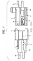
- numeral 11 designates a male connector member
- numeral 12 designates a female connector member.
- These male connector member 11 and female connector member 12 are provided with a male terminal 13 and a female terminal 14, respectively, which confront each other.
- the connector members 11 and 12 are provided with projections 16 and 17 as lock means.
- Numeral 15 designates an elastic contact
- numerals 18, 18, 19 and 19 designate electric wires having the terminals 13 and 14.
- Numeral 11a designates a connector housing of the male connector member 11
- numeral 12a designates a connector housing of the female connector member 12.
- Fig. 1 shows a state before the connector members 11 and 12 are jointed
- Fig. 2 show a state in which the same are jointed. From this jointed state, the connector members 11 and 12 are slid. in the disjointing directions, as shown in Fig. 3, to release the engagement (or lock) of the projections 16 and 17.
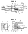
- Fig. 4 shows the state of the instant, at which the terminals 13 and 14 are disconnected.
- this connector is constructed: such that if the sliding stroke necessary for releasing the engagement (or releasing the lock) of the projections 16 and 17 is indicated by S1 (as referred to Fig. 3) and if the sliding stroke necessary for disconnecting the terminals 13 and 14 from each other is indicated by S2 (as referred to Fig. 4), the following relation is set: S1 ⁇ S2; and such that the terminals 13 and 14 are not disconnected from each other before the projections 26 and 27 are unlocked.
- the terminals 13 and 14 can be quickly (or as fast as possible) disconnected in a state without any obstruction to the disjoint by the lock means (i.e., the projections 16 and 17), so that the arc is hardly discharged between the terminals at that terminal disconnecting time. Even under a high voltage, therefore, it is possible to suppress the damage of the terminals or the like, as might otherwise be caused the terminal arc discharge).
- the second embodiment is applied to a water-proof connector.
- Numeral 21 designates a male connector member
- numeral 22 designates a female connector member.
- These male connector member 21 and female connector member 22 are provided with a male terminal 23 and a female terminal 24, respectively, which confront each other.
- the connector members 21 and 22 are provided with projections 26 and 27 as lock means.
- the connector members 21 and 22 are jointed to / disjoined from each other by the sliding motions in the longitudinal directions of the terminals, and the terminals 23 and 24 are connected to / disconnected from each other.
- the projections 26 and 27 are brought into engagement so that the connector members 21 and 22 are locked in the jointed state.
- Numeral 25 designates an elastic contact
- numeral 28 designates one electric wire having the female terminal 24 (although the other electric wire of the female terminal and the electric wires of the male terminal are not shown)
- Numeral 21a designates a connector housing of the male connector member
- numeral 22a designates a connector housing of the female connector member 22.
- this connector is provided as its water-proofing seal member with a cylindrical seal ring 29, which is disposed in the female connector member 22 and made of an elastic material such as rubber, and a cylindrical seal portion 30 which is disposed on the inner face of the male connector member 21.
- a cylindrical seal ring 29 comes into elastic contact with the seal portion 30 with the connector members 21 and 22 being jointed, as shown in Fig. 6, the connector member jointed portions are held water-tight so that the connected terminal portions are sealed water-proof.
- Fig. 7 shows the state in which the connector members 21 and 22 are slid in the disjointing directions from their jointed states to release the engagement (or release the lock) of the projections 26 and 27, and Fig. 8 shows the instant at which the terminals 23 and 24 are disconnected by further sliding the connector members 21 and 22.
- This connector is constructed, like the connector of the first embodiment: such that if the sliding stroke necessary for releasing the engagement (or the lock) of the projections 26 and 27 from each other is indicated by S1 (as referred to Fig. 7), if the sliding stroke necessary for disconnecting the terminals 23 and 24 from each other is indicated by S2 (as referred to Fig. 8) and if the sliding stroke necessary for the seal ring 29 to be separated (or to be unsealed) from the seal portion 30 is indicated by S3 (as referred to Fig.
- the terminals 23 and 24 can be quickly disconnected to suppress the arc discharge.
- the foregoing two embodiments use the lock means for making the locking/unlocking actions by the sliding motions of the connector members 11 and 12, and 21 and 22.
- the lock means may be exemplified by the non-slide type lock means having the structure, in which the connector members being jointed are fastened and fixed by fitting a fastening clamp on the outer circumference of the connector or in which the connectors are locked by screwing a bolt into the connector from the outer circumference of the same.
- the connector may be so modified by using the non-slide type lock means that the terminal disconnecting action is made after the lock is released.
- the terminals can be disconnected when the obstruction of the lock means (and the seal member in Aspect 3) to the disjoint disappears so that the disconnecting action can be quickly made. Therefore, the arc discharge hardly occurs between the terminals at the disconnecting time so that the damage from the arc distance can be suppressed even under a high voltage.
Landscapes
- Connector Housings Or Holding Contact Members (AREA)
- Details Of Connecting Devices For Male And Female Coupling (AREA)
Abstract
Description
| Frequency of Damages when Connector Active line Is Extracted at Voltage of 42 V : | ||||||||||
| Extracting Rate (mm/min) | Current Value (A) | |||||||||
| 1 | 2 | 5 | 10 | 20 | 25 | 30 | 40 | 60 | 80 | |
| 100 | ○ | × | ×× | ×× | ×× | ×× | ×× | |||
| 1000 | ○ | ○ | × | ×× | ||||||
| 2500 | ○ | ○ | ○ | ○ | × | |||||
| 5000 | ○ | ○ | ○ | ○ | × | |||||
| 10000 | ○ | ○ | × | × | ||||||
| 30000 | ○ | |||||||||
| 50000 | ○ | |||||||||
| ○: No Serious Damage after 10 Extractions of Live Wire | ||||||||||
| ×: Damages to Elastic Contact after 10 Extractions of Live Wire | ||||||||||
| X X : Serious Damages |
such that the
such that the
Claims (3)
- A connector comprising:male and female connector members enabled to be jointed to and disjointed from each other;male and female terminals adapted to be electrically connected with each other when said connector members are jointed; andlock means for locking said connector members disjointably, the connected states of said terminals are kept after said lock means is released to lose a obstruction thereof to the disjoint of said connector members.
- The connector according to Claim 1, wherein
the sliding motions in the directions for said male and female connector members to approach and leave each other, comprises:a sliding stroke S1 necessary for releasing the lock of said lock means, and a sliding stroke S2 necessary for disconnecting said terminals are set to satisfy the following relation:(a) jointing/disjointing step of said male and female connector members;(b) connecting/disconnecting step of said terminals;(c) locking/unlocking step of said lock means, and - The connector according to Claim 2, wherein
said male and female connector members comprise seal members adapted to be brought into and out of contact with each other by the sliding motions of said connector members for water-tight sealing/unsealing the connected portions of said male and female terminals, and
a sliding stroke S3 necessary for releasing the seal of said seal members is set to satisfy the following relation:
Applications Claiming Priority (2)
| Application Number | Priority Date | Filing Date | Title |
|---|---|---|---|
| JP2001171948A JP2002367718A (en) | 2001-06-07 | 2001-06-07 | connector |
| JP2001171948 | 2001-06-07 |
Publications (2)
| Publication Number | Publication Date |
|---|---|
| EP1265321A2 true EP1265321A2 (en) | 2002-12-11 |
| EP1265321A3 EP1265321A3 (en) | 2004-12-29 |
Family
ID=19013642
Family Applications (1)
| Application Number | Title | Priority Date | Filing Date |
|---|---|---|---|
| EP02012647A Withdrawn EP1265321A3 (en) | 2001-06-07 | 2002-06-06 | Connector |
Country Status (3)
| Country | Link |
|---|---|
| US (1) | US20030022544A1 (en) |
| EP (1) | EP1265321A3 (en) |
| JP (1) | JP2002367718A (en) |
Families Citing this family (6)
| Publication number | Priority date | Publication date | Assignee | Title |
|---|---|---|---|---|
| EP2302744B1 (en) * | 2009-09-24 | 2012-06-20 | Tyco Electronics France SAS | Electrical socket with supporting element, electrical plug with deformation pocket and plug assembly with at least one socket and one plug as well as a method for connecting a plug and a socket |
| US9142907B2 (en) * | 2013-12-10 | 2015-09-22 | Delphi Technologies, Inc. | Electrical connection system |
| US10211546B2 (en) | 2013-12-10 | 2019-02-19 | Aptiv Technologies Limited | Electrical connection system for shielded wire cable |
| US10109958B2 (en) | 2013-12-10 | 2018-10-23 | Delphi Technologies, Inc. | Electrical connection system for shielded wire cable |
| JP6810894B2 (en) * | 2017-07-14 | 2021-01-13 | 株式会社オートネットワーク技術研究所 | connector |
| US10849620B2 (en) * | 2018-09-14 | 2020-12-01 | Covidien Lp | Connector mechanisms for surgical stapling instruments |
Family Cites Families (8)
| Publication number | Priority date | Publication date | Assignee | Title |
|---|---|---|---|---|
| US3328744A (en) * | 1964-12-14 | 1967-06-27 | Amp Inc | Corona resistant lead and terminal assembly |
| GB1362265A (en) * | 1971-03-12 | 1974-08-07 | Cannon Electric Great Britain | Electrical connectors |
| JP2514994Y2 (en) * | 1991-07-30 | 1996-10-23 | 株式会社ピーエフユー | Stage insertion / extraction type connector |
| JPH0682772U (en) * | 1993-04-30 | 1994-11-25 | 日本航空電子工業株式会社 | Waterproof connector |
| JPH0955257A (en) * | 1995-08-09 | 1997-02-25 | Sumitomo Wiring Syst Ltd | Charging connector |
| US5997333A (en) * | 1996-08-09 | 1999-12-07 | Sumitomo Wiring Systems, Ltd. | Locking device for high-voltage cable connectors |
| JP2001307839A (en) * | 2000-04-17 | 2001-11-02 | Fujikura Ltd | Connector and electrical connection structure |
| JP2002352889A (en) * | 2001-05-22 | 2002-12-06 | Tokai Rika Co Ltd | Connector |
-
2001
- 2001-06-07 JP JP2001171948A patent/JP2002367718A/en active Pending
-
2002
- 2002-06-05 US US10/161,614 patent/US20030022544A1/en not_active Abandoned
- 2002-06-06 EP EP02012647A patent/EP1265321A3/en not_active Withdrawn
Also Published As
| Publication number | Publication date |
|---|---|
| US20030022544A1 (en) | 2003-01-30 |
| EP1265321A3 (en) | 2004-12-29 |
| JP2002367718A (en) | 2002-12-20 |
Similar Documents
| Publication | Publication Date | Title |
|---|---|---|
| US5695368A (en) | Electrical terminal with protected locking lance and a connector therefor | |
| US6953357B2 (en) | Packing and connector equipped with the same | |
| US8992242B2 (en) | Electrical connector assembly | |
| EP0975062A1 (en) | Electrical connector | |
| US6361378B1 (en) | Connector with a side retainer | |
| US20150050826A1 (en) | Waterproof connector | |
| US9673560B2 (en) | Laminated connector | |
| US5779493A (en) | Waterproofing connector | |
| US5980297A (en) | Lock arm deformation prevention construction | |
| KR100881499B1 (en) | Electrical connector assembly and connectors used therein | |
| CN1736004B (en) | Electrical connector with terminal position safety system | |
| JP2858727B2 (en) | Waterproof plug cover for waterproof connector | |
| US5593326A (en) | Electrical connector with secondary latch | |
| US7354287B1 (en) | Shorting connector | |
| WO1995017029A1 (en) | Modular connector assembly | |
| US5791923A (en) | Tab terminal with short circuiting spring member | |
| US20030022544A1 (en) | Connector | |
| US20010018283A1 (en) | Connector sealing structure | |
| JP2805436B2 (en) | Simple waterproof connector | |
| EP0721233A3 (en) | Protected connector assembly having double ended shorting clip | |
| JPH05266941A (en) | Waterproof connector | |
| US6783381B2 (en) | Water-proof connector and connector housing therefor | |
| EP0975061A2 (en) | A watertight connector with inertial locking mechanism | |
| JP2019515455A (en) | HVIL system | |
| US6116953A (en) | Electrical connector having a terminal position assurance device |
Legal Events
| Date | Code | Title | Description |
|---|---|---|---|
| PUAI | Public reference made under article 153(3) epc to a published international application that has entered the european phase |
Free format text: ORIGINAL CODE: 0009012 |
|
| AK | Designated contracting states |
Kind code of ref document: A2 Designated state(s): AT BE CH CY DE DK ES FI FR GB GR IE IT LI LU MC NL PT SE TR |
|
| AX | Request for extension of the european patent |
Free format text: AL;LT;LV;MK;RO;SI |
|
| PUAL | Search report despatched |
Free format text: ORIGINAL CODE: 0009013 |
|
| AK | Designated contracting states |
Kind code of ref document: A3 Designated state(s): AT BE CH CY DE DK ES FI FR GB GR IE IT LI LU MC NL PT SE TR |
|
| AX | Request for extension of the european patent |
Extension state: AL LT LV MK RO SI |
|
| AKX | Designation fees paid | ||
| REG | Reference to a national code |
Ref country code: DE Ref legal event code: 8566 |
|
| STAA | Information on the status of an ep patent application or granted ep patent |
Free format text: STATUS: THE APPLICATION IS DEEMED TO BE WITHDRAWN |
|
| 18D | Application deemed to be withdrawn |
Effective date: 20050630 |