EP1265316A2 - Horn antenna apparatus - Google Patents
Horn antenna apparatus Download PDFInfo
- Publication number
- EP1265316A2 EP1265316A2 EP02010078A EP02010078A EP1265316A2 EP 1265316 A2 EP1265316 A2 EP 1265316A2 EP 02010078 A EP02010078 A EP 02010078A EP 02010078 A EP02010078 A EP 02010078A EP 1265316 A2 EP1265316 A2 EP 1265316A2
- Authority
- EP
- European Patent Office
- Prior art keywords
- intersection
- line
- radio
- axis
- mode
- Prior art date
- Legal status (The legal status is an assumption and is not a legal conclusion. Google has not performed a legal analysis and makes no representation as to the accuracy of the status listed.)
- Withdrawn
Links
Images


Classifications
-
- H—ELECTRICITY
- H01—ELECTRIC ELEMENTS
- H01Q—ANTENNAS, i.e. RADIO AERIALS
- H01Q13/00—Waveguide horns or mouths; Slot antennas; Leaky-waveguide antennas; Equivalent structures causing radiation along the transmission path of a guided wave
- H01Q13/02—Waveguide horns
Definitions
- the present invention relates to a horn antenna apparatus for use in an antenna system for radar, radio communication and so forth and in the primary radiator of such an antenna system and for radiating radio waves into space with desired characteristics.
- Fig. 6 is a sectional view of a dual-mode type horn antenna apparatus among the conventional horn antenna apparatus shown in, for example, the 'Satellite Communication Technology' published by the 'Institute of Electronics, Information and Communication Engineers of Japan' on Nov. 10, 1980.
- reference numeral 1 denotes a radio-wave input portion having a circular inner waveguide diameter
- 3 a tapered waveguide portion
- the waveguide portion 3 is formed such that its inner diameter is increased from the side of the radio-wave input portion 1 toward the aperture portion 2.
- reference numeral 4 denotes a higher-mode generating portion having an inner diameter that changes stepwise or in a tapered manner and used for generating higher-mode radio waves of out of the radio waves fed.
- radio waves having an electric field distribution in a TE11 mode as the basic mode of the circular waveguide are excited.
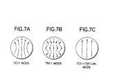
- the electric field distribution in the TE11 mode is shown in Fig. 7A.
- some of the radio waves having the electric field distribution in the TE11 mode in the radio-wave input portion 1 are converted into a higher mode such as a TM11 mode.
- the electric field distribution in the TM11 mode is shown in Fig. 7B.
- the radio waves in the dominant mode and the higher mode propagate through the waveguide portion 3 and reaches the aperture portion 2.
- the inner diameter ⁇ D and the taper angle ⁇ of the inner diameter of the higher-mode generating portion 4 are set at proper values so that the amplitude and phase of the higher mode such as the TM11 mode generated in the higher-mode generating portion 4 may satisfy desired values.
- the aperture distribution of the radio waves in the aperture portion 2 can be made to conform to an electric field distribution shown in Fig. 7C.
- the electric field distribution in the aperture portion shown in Fig. 7C is what is obtained by superposing the electric field distribution in the higher mode such as the TM11 mode on the electric field distribution in the TE11 mode and becomes a rotationally symmetrical electric field distribution without generating cross polarization.
- the quantity (amplitude and phase) of the TM11 Mode and the like generated in the higher-mode generating portion 4 can be set at an ideal value at a predetermined frequency of fo.
- a deviation in the quantity of the higher mode thus generated occurs when the frequency deviates from fo and while the radio wave propagating through the tapered waveguide portion 3, the phase quantity in the higher mode also deviates with respect to the dominant mode.
- the electric field distribution generated in the aperture portion 2 does not become rotationally symmetrical in case where the frequency is thus deviated and the problem is that the cross polarization is generated therein.
- An object of the present invention made to solve the foregoing problems is to provide a horn antenna apparatus which is rotationally symmetrical and generates a desired quantity of higher mode and a smaller quantity of cross polarization over a wide frequency range.
- a horn antenna apparatus including: a radio-wave input portion for receiving radio waves; a waveguide portion for propagating the radio waves received; and an aperture portion for radiating the radio waves propagated by said waveguide portion into space; wherein in said waveguide portion, the inclination of a line of intersection crossing aplane including an axis in the direction of propagating radio waves with respect to said axis is not fixed but continuously varied; and wherein a distance between said line of intersection and said axis increases from the side of said radio-wave input portion toward the side of said aperture portion.
- the distance between said line of intersection and said axis may decrease, in part of said line of intersection, from the side of said radio-wave input portion toward the side of said aperture portion.
- a horn antenna apparatus including: a radio-wave input portion for receiving radio waves; a waveguide portion for propagating the radio waves received; and an aperture portion for radiating the radio waves propagated by said waveguide portion into space; wherein in said waveguide portion, the inclination of a line of intersection crossing a plane including an axis in the direction of propagating radio waves with respect to said axis is not fixed but continuously varied in part of said line of intersection; and wherein the distance between said line of intersection and said axis increases from the side of said radio-wave input portion toward the side of said aperture portion.
- the distance between said line of intersection and said axis may increase, in part of said line of intersection, from the side of said radio-wave input portion toward the side of said aperture portion.
- a horn antenna apparatus including: a radio-wave input portion for receiving radio waves; a waveguide portion for propagating the radio waves received; and an aperture portion for radiating the radio waves propagated by said waveguide portion into space; wherein in said waveguide portion, a line of intersection crossing a plane including an axis in the direction of propagating radio waves includes a plurality of straight lines; and wherein the distance between said line of intersection and said axis increases, in part of said line of intersection, from the side of said radio-wave input portion toward said of said aperture portion.
- Fig. 1 is a sectional view of a horn antenna apparatus according to Embodiment 1 of the invention.
- reference numeral 1 denotes a radio-wave input portion for receiving radio waves, the radio-wave input portion 1 being formed with a circular or rectangular waveguide, a coaxial cable or the like; 2, an aperture portion of a horn antenna for radiating radio waves into space; and 5, a waveguide portion that is circular or elliptic in cross section, the waveguide portion 5 being used for propagating radio waves in the direction of the axis Z (central axis of the waveguide portion 5) shown in Fig. 1.
- this waveguide portion 5 is formed such that an inclination of a line of intersection (line of intersection S of Fig. 1) crossing a plane including the axis Z with respect to the axis Z is not fixed but continuously varied. Further, this line of intersection S is formed so that the distance between the line of intersection S and the axis Z increases from the side of the radio-wave input portion 1 toward that of the aperture portion 2. In other words, the rate of change of the inner diameter of the waveguide portion 5 in the direction of the axis Z is not fixed but continuously varied and has a positive value.
- the line of intersection S is a line segment in which the inner wall of the waveguide portion 5 and the plane including the axis Z cross each other.
- Radio waves are fed into the radio-wave input portion 1 by a waveguide, a coaxial cable or the like.
- radio waves in a TE11 mode are excited. Some of the excited radio waves in the TE11 mode are converted to those in the higher mode in the waveguide portion 5.
- the higher mode is excited (converted from the lower mode to the higher mode) everywhere in the direction of the axis Z of the waveguide portion 5.
- the higher mode such as a TM11 mode and the TE12 mode are successively generated in the direction of the axis Z and reaches the aperture portion 2. It is thus possible to obtain such a horn antenna apparatus that the electric field distribution in the aperture portion 2 is rotationally symmetrical with the generation of a cross polarization component being kept under control over a wide frequency range as shown Fig. 7C by determining the shape of the line of intersection S so that an amplitude and a phase as the generated quantity of higher mode such as the TM11 mode generated in the waveguide portion 5 conform to desired values with respect to each higher mode.
- Fig. 2 is a sectional view of a horn antenna apparatus according to Embodiment 2 of the invention.
- reference numeral 6 denotes a waveguide portion that is circular or elliptic in cross section, the waveguide portion 6 being used for propagating radio waves in the direction of the axis Z (central axis of the waveguide portion 6) shown in Fig. 2.
- this waveguide portion 6 is formed such that an inclination of a line of intersection (line of intersection T of Fig. 2) crossing a plane including the axis Z with respect to the axis Z is not fixed but continuously varied.
- this line of intersection T is formed so that the distance between the line of intersection T and the axis Z decreases, in part of the line of intersection T , from the side of the radio-wave input portion 1 toward that of the aperture portion 2.
- the distance between the line of intersection T and the axis Z decreases in a place A from the side of the radio-wave input portion 1 toward that of the aperture portion 2.
- the rate of change of the inner diameter of the waveguide portion 5 in the direction of the axis Z is not fixed but continuously varied and even has a negative value.
- the waveguide portion 6 has a throttled shape in the place A of Fig. 2.
- the line of intersection T is a line segment in which the inner wall of the waveguide portion 6 and the plane including the axis Z cross each other.
- any portions having like reference numerals in Fig. 1 designate like or corresponding portions in Fig. 1.
- Radio waves are fed into the radio-wave input portion 1 by a waveguide, a coaxial cable or the like.
- radio waves in the TE11 mode are excited. Some of the excited radio waves in the TE11 mode are converted to those in the higher mode in the waveguide portion 6.
- the higher mode is excited (converted from the lower mode to the higher mode) everywhere in the direction of the axis Z of the waveguide portion 6.
- the higher mode such as the TM11 mode and the TE12 mode are successively generated in the direction of the axis Z and reaches the aperture portion 2.
- the electric field distribution in the aperture portion 2 is rotationally symmetrical with the generation of a cross polarization component being kept under control over a wide frequency range as shown Fig. 7C by determining the shape of the line of intersection T so that an amplitude and a phase as the generated quantity of higher mode such as the TM11 mode generated in the waveguide portion 6 conform to desired values.
- the horn antenna apparatus according to Embodiment 2 of the invention has the throttled shaped as described above whereby to obtain a reverse wavefront effect, the whole length of the horn antenna apparatus can be shortened and the electric field distribution in the aperture portion 2 is made rotationally symmetrical with the generation of a cross polarization component being kept under control over a wide frequency range. Further, by providing a plurality of throttled shapes respectively in a plurality of places of the waveguide portion 6, the electric field distribution in the aperture portion 2 is made rotationally symmetrical with the generation of the cross polarization being kept under control in a plurality of frequency bands.
- Fig. 3 is a graph showing an example of power generation in the higher mode in each position from the radio-wave input portion 1 over the aperture portion 2 in the horn antenna apparatus having the waveguide portion formed as in Embodiment 1 or 2.
- the vertical axis refers to the power level generated. As shown in Fig.
- the relation between the tilted angle of the tapered portion (generally called the flare angle of a horn) and the length of the waveguide portion is such that the smaller the tapered tilted angle, the longer the length of the waveguide portion in order to obtain an electric field distribution with a smaller cross polarization component in the aperture portion.
- the horn antenna apparatus so arranged as in Embodiments 1 and 2 that relation is not established, whereby a horn antenna apparatus having the electric field distribution with the smaller cross polarization in the aperture portion is obtainable with a relatively less longer waveguide portion.
- a waveguide portion may be formed with a tapered portion having the line of intersection S or the line of intersection T and a straight line as shown in Fig. 4A or 4B; that is, the line of intersection S or T may be provided in part of the waveguide portion.
- Figs. 4A and 4B are sectional views of horn antenna apparatus according to Embodiment 3 of the invention: in Fig. 4A, a waveguide portion 8 has a tapered portion on the side of the radio-wave input portion 1; and in Fig.
- the waveguide portion 8 has a tapered portion on the side of the aperture portion 2.
- Embodiment 3 of the invention has an effect similar to those described in Embodiments 1 and 2 thereof.
- Fig. 5 is a sectional view of a horn antenna apparatus according to Embodiment 4 of the invention.
- reference numeral 7 denotes a waveguide portion that is circular or elliptic in cross section, the waveguide portion 7 being used for propagating radio waves in the direction of the axis Z (central axis of the waveguide portion 7) shown in Fig. 5.
- This waveguide portion 7 is formed such that a line of intersection (line of intersection U of Fig. 5) crossing a plane including the axis Z is formed with a plurality of straight lines.
- the line of intersection U is formed so that the distance between the line of intersection U and the axis Z decreases, in part of the line of intersection U , from the side of the radio-wave input portion 1 toward that of the aperture portion 2.
- the distance between the line of intersection U and the axis Z decreases in a place B from the side of the radio-wave input portion 1 toward that of the aperture portion 2.
- the waveguide portion 7 has a throttled shape in the place B of Fig. 5.
- the line of intersection U is a line segment in which the inner wall of the waveguide portion 7 and the plane including the axis Z cross each other.
- any portions having like reference numerals in Fig.1 designate like or corresponding portions in Fig. 1.
- the horn antenna apparatus according to Embodiment 4 of the invention has the throttled shaped as described above whereby to obtain a reverse wavefront effect, the whole length of the horn antenna apparatus can be shortened and the electric field distribution in the aperture portion 2 is made rotationally symmetrical with the generation of the cross polarization being kept under control over a wide frequency range as described in Embodiment 2.
- the horn antenna apparatus in the waveguide portion, as the inclination of the line of intersection crossing the plane including the axis in the direction of propagating radio waves is not fixed but continuously varied, the higher mode is excited, whereby it is possible to obtain the horn antenna apparatus having the electric field distribution that is rotationally symmetrical with the smaller cross polarization component over a wide frequency range in its aperture portion.
- the reverse wavefront is generated as the waveguide portion has the throttled shape and the whole length of the horn antenna apparatus can be shortened, whereby it is possible to obtain the horn antenna apparatus having the electric field distribution that is rotationally symmetrical with the smaller cross polarization component over a wide frequency range in its aperture portion.
Landscapes
- Waveguide Aerials (AREA)
- Waveguide Switches, Polarizers, And Phase Shifters (AREA)
Abstract
Description
Fig. 5 is a sectional view of a horn antenna apparatus according to
Claims (5)
- A horn antenna apparatus, comprising:a radio-wave input portion (1) for receiving radio waves;a waveguide portion (5, 6) for propagating the radio waves received; andan aperture portion (2) for radiating the radio waves propagated by the waveguide portion (5, 6) into space;wherein in the waveguide portion (5, 6), the inclination of a line of intersection (S, T) crossing a plane including an axis (Z) in the direction of propagating radio waves with respect to the axis (Z) is not fixed but continuously varied; andwherein a distance between the line of intersection (S, T) and the axis (Z) increases from the side of the radio-wave input portion (1) toward the side of the aperture portion (2).
- The apparatus according to claim 1,
wherein the distance between the line of intersection (S, T) and the axis (Z) decreases, in part of the line of intersection (S, T), from the side of the radio-wave input portion (1) toward the side of the aperture portion (2). - A horn antenna apparatus, comprising:a radio-wave input portion (1) for receiving radio waves;a waveguide portion (5, 6) for propagating the radio waves received; andan aperture portion (2) for radiating the radio waves propagated by the waveguide portion (5, 6) into space;wherein in the waveguide portion (5, 6), the inclination of a line of intersection (S, T) crossing a plane including an axis (Z) in the direction of propagating radio waves with respect to the axis (Z) is not fixed but continuously varied in part of the line of intersection (S, T); andwherein the distance between the line of intersection (S, T) and the axis (Z) increases from the side of the radio-wave input portion (1) toward the side of the aperture portion (2).
- The apparatus according to claim 3,
wherein the distance between the line of intersection (S, T) and the axis (Z) increases, in part of the line of intersection (S, T), from the side of the radio-wave input portion (1) from the side of the aperture portion (2). - A horn antenna apparatus, comprising:a radio-wave input portion (1) for receiving radio waves;a waveguide portion (7) for propagating the radio waves received; andan aperture portion (2) for radiating the radio waves propagated by the waveguide portion (7) into space;wherein in the waveguide portion (7), a line of intersection (U) crossing a plane including an axis (Z) in the direction of propagating radio waves includes a plurality of straight lines (7); andwherein the distance between the line of intersection (U) and the axis (Z) increases, in part of the line of intersection (U), from the side of the radio-wave input portion (1) toward the side of the aperture portion (2).
Applications Claiming Priority (2)
| Application Number | Priority Date | Filing Date | Title |
|---|---|---|---|
| JP2001172557A JP2002368529A (en) | 2001-06-07 | 2001-06-07 | Horn antenna device |
| JP2001172557 | 2001-06-07 |
Publications (2)
| Publication Number | Publication Date |
|---|---|
| EP1265316A2 true EP1265316A2 (en) | 2002-12-11 |
| EP1265316A3 EP1265316A3 (en) | 2003-10-29 |
Family
ID=19014161
Family Applications (1)
| Application Number | Title | Priority Date | Filing Date |
|---|---|---|---|
| EP02010078A Withdrawn EP1265316A3 (en) | 2001-06-07 | 2002-05-06 | Horn antenna apparatus |
Country Status (3)
| Country | Link |
|---|---|
| US (1) | US6642901B2 (en) |
| EP (1) | EP1265316A3 (en) |
| JP (1) | JP2002368529A (en) |
Families Citing this family (10)
| Publication number | Priority date | Publication date | Assignee | Title |
|---|---|---|---|---|
| JP3879548B2 (en) * | 2002-03-20 | 2007-02-14 | 三菱電機株式会社 | Waveguide type demultiplexer |
| US6937202B2 (en) * | 2003-05-20 | 2005-08-30 | Northrop Grumman Corporation | Broadband waveguide horn antenna and method of feeding an antenna structure |
| US7161550B2 (en) | 2004-04-20 | 2007-01-09 | Tdk Corporation | Dual- and quad-ridged horn antenna with improved antenna pattern characteristics |
| US7755557B2 (en) | 2007-10-31 | 2010-07-13 | Raven Antenna Systems Inc. | Cross-polar compensating feed horn and method of manufacture |
| JP4518141B2 (en) | 2007-12-17 | 2010-08-04 | 日本電気株式会社 | Image collation method, image collation apparatus, and image collation program |
| US8026859B2 (en) * | 2008-08-07 | 2011-09-27 | Tdk Corporation | Horn antenna with integrated impedance matching network for improved operating frequency range |
| US8514140B1 (en) * | 2009-04-10 | 2013-08-20 | Lockheed Martin Corporation | Dual-band antenna using high/low efficiency feed horn for optimal radiation patterns |
| KR102125949B1 (en) * | 2015-07-17 | 2020-06-24 | 한국전자통신연구원 | Horn antenna apparatus |
| US20170040709A1 (en) * | 2015-08-04 | 2017-02-09 | Nidec Elesys Corporation | Radar apparatus |
| US10027004B2 (en) * | 2016-07-28 | 2018-07-17 | The Boeing Company | Apparatus including a dielectric material disposed in a waveguide, wherein the dielectric permittivity is lower in a mode combiner portion than in a mode transition portion |
Family Cites Families (4)
| Publication number | Priority date | Publication date | Assignee | Title |
|---|---|---|---|---|
| US3898669A (en) * | 1973-05-15 | 1975-08-05 | Us Air Force | Apparatus for providing higher order mode compensation in horn antennas |
| DE2655436C3 (en) * | 1976-12-07 | 1982-01-28 | Gerhard Prof. Dr.-Ing. 8012 Ottobrunn Flachenecker | A funnel antenna with a multi-section funnel |
| SU1665432A1 (en) * | 1989-01-05 | 1991-07-23 | Институт прикладной физики АН СССР | Transducer of higher circular waveguide modes into mirror beam guide waves |
| US6396453B2 (en) * | 2000-04-20 | 2002-05-28 | Ems Technologies Canada, Ltd. | High performance multimode horn |
-
2001
- 2001-06-07 JP JP2001172557A patent/JP2002368529A/en active Pending
-
2002
- 2002-02-26 US US10/082,114 patent/US6642901B2/en not_active Expired - Fee Related
- 2002-05-06 EP EP02010078A patent/EP1265316A3/en not_active Withdrawn
Also Published As
| Publication number | Publication date |
|---|---|
| EP1265316A3 (en) | 2003-10-29 |
| US6642901B2 (en) | 2003-11-04 |
| JP2002368529A (en) | 2002-12-20 |
| US20020186174A1 (en) | 2002-12-12 |
Similar Documents
| Publication | Publication Date | Title |
|---|---|---|
| US4308932A (en) | Loudspeaker horn | |
| US5642121A (en) | High-gain, waveguide-fed antenna having controllable higher order mode phasing | |
| US20180108996A1 (en) | Integrated single-piece antenna feed and circular polarizer | |
| US6642901B2 (en) | Horn antenna apparatus | |
| US4947181A (en) | Asymmetrical biconical horn antenna | |
| US10297924B2 (en) | Radar antenna unit and radar device | |
| US20170018850A1 (en) | Horn antenna apparatus | |
| US20180241497A1 (en) | Planar electromagnetic wave generation apparatus for concentrating orbital angular momentum and method therefor | |
| KR20180055489A (en) | Corrugated horn antenna for high monopulse tracking capability in wide frequency bandwidth | |
| US5995057A (en) | Dual mode horn reflector antenna | |
| US4903038A (en) | Horn antenna arrangement | |
| JPH0531843B2 (en) | ||
| US20020190911A1 (en) | Multimode horn antenna | |
| JP2003163501A (en) | Curved waveguide element and transmission device comprising curved waveguide element | |
| JP2003188634A (en) | Horn antenna assembly | |
| US6411263B1 (en) | Multi-mode horn | |
| JP4178265B2 (en) | Waveguide horn antenna, antenna device, and radar device | |
| KR101306789B1 (en) | Multi-mode horn antenna with modified aperture and its method of design | |
| JP3816408B2 (en) | Multimode horn antenna | |
| Taylor et al. | Constant directivity circular-arc arrays of dipole elements | |
| JP2020027092A (en) | Probe holding device and antenna pattern measuring device using the same | |
| JPS63144605A (en) | Nondirectional antenna within horizontal plane | |
| JP2922562B2 (en) | Corrugated horn antenna | |
| JP6913586B2 (en) | Antenna device | |
| JPH05199030A (en) | Dual mode horn antenna |
Legal Events
| Date | Code | Title | Description |
|---|---|---|---|
| PUAI | Public reference made under article 153(3) epc to a published international application that has entered the european phase |
Free format text: ORIGINAL CODE: 0009012 |
|
| AK | Designated contracting states |
Kind code of ref document: A2 Designated state(s): AT BE CH CY DE DK ES FI FR GB GR IE IT LI LU MC NL PT SE TR |
|
| AX | Request for extension of the european patent |
Free format text: AL;LT;LV;MK;RO;SI |
|
| PUAL | Search report despatched |
Free format text: ORIGINAL CODE: 0009013 |
|
| AK | Designated contracting states |
Kind code of ref document: A3 Designated state(s): AT BE CH CY DE DK ES FI FR GB GR IE IT LI LU MC NL PT SE TR |
|
| AX | Request for extension of the european patent |
Extension state: AL LT LV MK RO SI |
|
| 17P | Request for examination filed |
Effective date: 20031119 |
|
| AKX | Designation fees paid |
Designated state(s): DE FR |
|
| 17Q | First examination report despatched |
Effective date: 20040621 |
|
| STAA | Information on the status of an ep patent application or granted ep patent |
Free format text: STATUS: THE APPLICATION HAS BEEN WITHDRAWN |
|
| 18W | Application withdrawn |
Effective date: 20050801 |