EP1265307A1 - Polymer cell - Google Patents
Polymer cell Download PDFInfo
- Publication number
- EP1265307A1 EP1265307A1 EP00976340A EP00976340A EP1265307A1 EP 1265307 A1 EP1265307 A1 EP 1265307A1 EP 00976340 A EP00976340 A EP 00976340A EP 00976340 A EP00976340 A EP 00976340A EP 1265307 A1 EP1265307 A1 EP 1265307A1
- Authority
- EP
- European Patent Office
- Prior art keywords
- ion
- electrolyte layer
- negative electrode
- conductive compound
- battery
- Prior art date
- Legal status (The legal status is an assumption and is not a legal conclusion. Google has not performed a legal analysis and makes no representation as to the accuracy of the status listed.)
- Granted
Links
Images


Classifications
-
- H—ELECTRICITY
- H01—ELECTRIC ELEMENTS
- H01M—PROCESSES OR MEANS, e.g. BATTERIES, FOR THE DIRECT CONVERSION OF CHEMICAL ENERGY INTO ELECTRICAL ENERGY
- H01M4/00—Electrodes
- H01M4/02—Electrodes composed of, or comprising, active material
- H01M4/62—Selection of inactive substances as ingredients for active masses, e.g. binders, fillers
- H01M4/621—Binders
-
- H—ELECTRICITY
- H01—ELECTRIC ELEMENTS
- H01M—PROCESSES OR MEANS, e.g. BATTERIES, FOR THE DIRECT CONVERSION OF CHEMICAL ENERGY INTO ELECTRICAL ENERGY
- H01M10/00—Secondary cells; Manufacture thereof
- H01M10/05—Accumulators with non-aqueous electrolyte
- H01M10/058—Construction or manufacture
-
- H—ELECTRICITY
- H01—ELECTRIC ELEMENTS
- H01M—PROCESSES OR MEANS, e.g. BATTERIES, FOR THE DIRECT CONVERSION OF CHEMICAL ENERGY INTO ELECTRICAL ENERGY
- H01M10/00—Secondary cells; Manufacture thereof
- H01M10/05—Accumulators with non-aqueous electrolyte
- H01M10/052—Li-accumulators
-
- H—ELECTRICITY
- H01—ELECTRIC ELEMENTS
- H01M—PROCESSES OR MEANS, e.g. BATTERIES, FOR THE DIRECT CONVERSION OF CHEMICAL ENERGY INTO ELECTRICAL ENERGY
- H01M10/00—Secondary cells; Manufacture thereof
- H01M10/05—Accumulators with non-aqueous electrolyte
- H01M10/056—Accumulators with non-aqueous electrolyte characterised by the materials used as electrolytes, e.g. mixed inorganic/organic electrolytes
- H01M10/0564—Accumulators with non-aqueous electrolyte characterised by the materials used as electrolytes, e.g. mixed inorganic/organic electrolytes the electrolyte being constituted of organic materials only
- H01M10/0565—Polymeric materials, e.g. gel-type or solid-type
-
- H—ELECTRICITY
- H01—ELECTRIC ELEMENTS
- H01M—PROCESSES OR MEANS, e.g. BATTERIES, FOR THE DIRECT CONVERSION OF CHEMICAL ENERGY INTO ELECTRICAL ENERGY
- H01M4/00—Electrodes
- H01M4/02—Electrodes composed of, or comprising, active material
- H01M4/04—Processes of manufacture in general
- H01M4/0402—Methods of deposition of the material
- H01M4/0416—Methods of deposition of the material involving impregnation with a solution, dispersion, paste or dry powder
-
- H—ELECTRICITY
- H01—ELECTRIC ELEMENTS
- H01M—PROCESSES OR MEANS, e.g. BATTERIES, FOR THE DIRECT CONVERSION OF CHEMICAL ENERGY INTO ELECTRICAL ENERGY
- H01M4/00—Electrodes
- H01M4/02—Electrodes composed of, or comprising, active material
- H01M4/36—Selection of substances as active materials, active masses, active liquids
- H01M4/362—Composites
- H01M4/366—Composites as layered products
-
- H—ELECTRICITY
- H01—ELECTRIC ELEMENTS
- H01M—PROCESSES OR MEANS, e.g. BATTERIES, FOR THE DIRECT CONVERSION OF CHEMICAL ENERGY INTO ELECTRICAL ENERGY
- H01M4/00—Electrodes
- H01M4/02—Electrodes composed of, or comprising, active material
- H01M4/36—Selection of substances as active materials, active masses, active liquids
- H01M4/58—Selection of substances as active materials, active masses, active liquids of inorganic compounds other than oxides or hydroxides, e.g. sulfides, selenides, tellurides, halogenides or LiCoFy; of polyanionic structures, e.g. phosphates, silicates or borates
- H01M4/583—Carbonaceous material, e.g. graphite-intercalation compounds or CFx
-
- H—ELECTRICITY
- H01—ELECTRIC ELEMENTS
- H01M—PROCESSES OR MEANS, e.g. BATTERIES, FOR THE DIRECT CONVERSION OF CHEMICAL ENERGY INTO ELECTRICAL ENERGY
- H01M4/00—Electrodes
- H01M4/02—Electrodes composed of, or comprising, active material
- H01M4/62—Selection of inactive substances as ingredients for active masses, e.g. binders, fillers
- H01M4/621—Binders
- H01M4/622—Binders being polymers
-
- H—ELECTRICITY
- H01—ELECTRIC ELEMENTS
- H01M—PROCESSES OR MEANS, e.g. BATTERIES, FOR THE DIRECT CONVERSION OF CHEMICAL ENERGY INTO ELECTRICAL ENERGY
- H01M10/00—Secondary cells; Manufacture thereof
- H01M10/05—Accumulators with non-aqueous electrolyte
- H01M10/052—Li-accumulators
- H01M10/0525—Rocking-chair batteries, i.e. batteries with lithium insertion or intercalation in both electrodes; Lithium-ion batteries
-
- H—ELECTRICITY
- H01—ELECTRIC ELEMENTS
- H01M—PROCESSES OR MEANS, e.g. BATTERIES, FOR THE DIRECT CONVERSION OF CHEMICAL ENERGY INTO ELECTRICAL ENERGY
- H01M2300/00—Electrolytes
- H01M2300/0017—Non-aqueous electrolytes
- H01M2300/0025—Organic electrolyte
- H01M2300/0028—Organic electrolyte characterised by the solvent
- H01M2300/0037—Mixture of solvents
-
- H—ELECTRICITY
- H01—ELECTRIC ELEMENTS
- H01M—PROCESSES OR MEANS, e.g. BATTERIES, FOR THE DIRECT CONVERSION OF CHEMICAL ENERGY INTO ELECTRICAL ENERGY
- H01M2300/00—Electrolytes
- H01M2300/0017—Non-aqueous electrolytes
- H01M2300/0065—Solid electrolytes
- H01M2300/0082—Organic polymers
-
- H—ELECTRICITY
- H01—ELECTRIC ELEMENTS
- H01M—PROCESSES OR MEANS, e.g. BATTERIES, FOR THE DIRECT CONVERSION OF CHEMICAL ENERGY INTO ELECTRICAL ENERGY
- H01M4/00—Electrodes
- H01M4/02—Electrodes composed of, or comprising, active material
- H01M4/04—Processes of manufacture in general
- H01M4/043—Processes of manufacture in general involving compressing or compaction
-
- Y—GENERAL TAGGING OF NEW TECHNOLOGICAL DEVELOPMENTS; GENERAL TAGGING OF CROSS-SECTIONAL TECHNOLOGIES SPANNING OVER SEVERAL SECTIONS OF THE IPC; TECHNICAL SUBJECTS COVERED BY FORMER USPC CROSS-REFERENCE ART COLLECTIONS [XRACs] AND DIGESTS
- Y02—TECHNOLOGIES OR APPLICATIONS FOR MITIGATION OR ADAPTATION AGAINST CLIMATE CHANGE
- Y02E—REDUCTION OF GREENHOUSE GAS [GHG] EMISSIONS, RELATED TO ENERGY GENERATION, TRANSMISSION OR DISTRIBUTION
- Y02E60/00—Enabling technologies; Technologies with a potential or indirect contribution to GHG emissions mitigation
- Y02E60/10—Energy storage using batteries
Definitions
- the present invention relates to a polymer battery, more particularly a polymer battery using an ion-conductive compound which acts reversibly at ambient temperature.
- the polymer battery uses the ion-conductive compound and a negative electrode containing, as an active material, a carbon material formed of graphite particles having amorphous carbon attached to the surface thereof.
- organic electrolytes formed of electrolytic salts dissolved in organic solvents are commonly used.
- the organic electrolytes are liable to leak out of components, generate the elution of electrode materials and volatilize. Therefore, there have been a problem in long-term reliability and a problem of scattering electrolytes during a sealing process.
- J.Electronchm. Soc., Vol.137, 2009 (1990), Japanese Unexamined Patent Publications Nos. HEI 4(1992)-115457, HEI 4(1992)-115458 and HEI 4(1992)-237971 disclose batteries using graphite type carbon materials as negative electrode active materials
- Japanese Unexamined Patent Publications Nos. HEI 4(1992)-368778, HEI 5(1993)-28996 and HEI 5(1993)-114421 disclose batteries using surface-treated graphite type carbon materials as negative electrode active materials.
- the graphite type carbon materials can provide a discharge capacity almost equal to a theoretical capacity in organic electrolytes formed mainly of ethylene carbonate (EC). Since the charge-discharge potential thereof is slightly higher than the lithium dissolution-deposition potential and is extremely flat, it is possible to realize high-capacity secondary batteries with flat battery voltage by producing the batteries using graphite type carbon materials as negative electrode active materials.
- EC ethylene carbonate
- PC propylene carbonate
- a solvent for organic electrolytes is widely used as a solvent for electrolytes of lithium batteries since it has a large potential window, a low coagulation point (-70 °C ) and a high chemical stability.
- ion-conductive polymers having a high ion conductivity have been reported, and are extensively studied as one means for solving the above-mentioned problems.
- ion-conductive polymers presently under study homopolymers and copolymers composed of ethylene oxide as a fundamental unit, which are in the form of straight-chain polymers, crosslinked network polymers or comb-form polymers have been proposed and are almost put in practical use.
- Various batteries using the above-mentioned ion-conductive polymers are described in patent publications and others, which are typified, for example, by U.S. Patent No. 4,303,784 (1981) to Armand et.
- the electrolyte layers also receive compression and relaxation stress. Accordingly, it is also necessary to consider not only the improvement of the ion conductivity but also the improvement of mechanical properties for improving the performance of the ion-conductive polymers.
- the inventors of the present invention have found that the use of graphite particles having amorphous carbon attached to the surface thereof for a negative electrode active material suppresses the decomposition of an ion-conductive compound contained in an ion conductor, further reduces the decline of the mechanical strength of an electrolyte with charge-discharge cycles and improves the performance of a battery using the ion-conductive compound.
- the present invention provides a polymer battery comprising a negative electrode comprising at least a carbon material as an active material, an electrolyte layer, and a positive electrode comprising at least a lithium-containing chalcogenide as an active material, characterized in that the electrolyte layer contains an ion-conductive compound and a polymer fiber, and the carbon material comprises graphite particles having amorphous carbon attached to the surface thereof.
- the present invention provides a polymer battery more excellent in the following points than the prior-art batteries, especially a polymer battery suitable for a small-size, light-weight battery:
- the negative electrode active material is comprised of the graphite particles having amorphous carbon attached to the surface thereof, the electrolyte layer containing the ion-conductive compound can be prevented from decomposing. Thereby the leakage can be eliminated and the long-term reliability can be improved.
- the graphite particles having amorphous carbon attached to the surface thereof can be obtained as follows: A particulate carbon material to be a core (referred to as “core carbon material” or “carbon material to be a core” or simply “core” hereinafter) is dipped in a raw material for a coating carbon material (for example, coal or petroleum heavy oil such as tar, pitch or the like; referred to simply as “heavy oil, etc.” hereinafter), and then, is separated from the heavy oil, etc. At this time, if a specific means is adapted, a carbon material in which the surface of the core is uniformly covered with pitch can be produced. The obtained carbon material is baked to give the above-mentioned graphite particles.
- core carbon material for example, coal or petroleum heavy oil such as tar, pitch or the like; referred to simply as “heavy oil, etc.” hereinafter
- the thus obtained particles of the carbon material of two-layer structure are spherical or ellipsoidal, or in a form approximate thereto, and have a form of carbon crystals whose edges are rounded. Further, measurement by a BET method has clearly shown that the particles after the above-described treatment have a specific surface area smaller than that of the core carbon material before the treatment and that pores, which are related to the specific surface area by the BET method, are closed in some manner.
- pores related to the specific surface area measured by the BET method are filled by adhesion or coating of carbon of the heavy oil, etc., and the specific surface area is 5 m 2 /g of smaller (preferably about 1 to 5 m 2 /g). If the specific surface area is larger than 5 m 2 /g, it is unpreferable because a contact area with the electrolyte becomes larger and side reaction with the ion-conductive compound takes place more easily.
- the carbon material to be the core is used a graphite material of high crystallinity whose average interplanar distance (d 002 ) in plane (002) is 0.335 to 0.340 nm, whose crystalline unit cell thickness (Lc) in a direction of plane (002) is 10 nm or more (more preferably, 40 nm or more) and whose crystalline unit cell thickness (La) in a direction of plane (110) is 10 nm or more (more preferably, 50 nm or more) by X-ray wide-angle diffraction analysis. If (d 002 ) is larger than 0.340 nm and (Lc) and (La) are smaller than 10 nm, it is unpreferable because the carbon material has low crystallinity and the discharge capacity decreases.
- the crystallinity of the amorphous carbon adhering to or coating the surface of the core is lower than the above-mentioned crystallinity of the core.
- the carbon material of the present invention has an absolute specific gravity within the range of 1.50 to 2.26 g/cm 3 . If the absolute specific gravity is lower than 1.50 g/cm 3 , it is not preferable because the filling factor of the negative electrode active material in the battery is low and the energy density is low. If the absolute specific gravity is higher than 2.26 g/cm 3 , the carbon material forms graphite single crystal and become poor in formability as a battery material.
- the electrolyte layer contains an ion-conductive compound, a polymer fiber and optionally a Li salt.
- Acrylates which are the following precursors of ion-conductive compounds are preferred since theircrosslinking reaction degree is high. That is because the reactivity of the acrylates is considered higher in the crosslinking reaction since methyl groups of methacrylates make steric hindrance.
- methyl, ethyl, propyl and the like are mentioned as lower alkyl groups having a carbon number of one or more.
- R 1 ' is a hydrogen atom or a lower alkyl group having a carbon number of one or more
- R 2 ' and R 3 ' are independently a hydrogen atom or a lower alkyl group having a carbon number of one or more
- R 4 ' and R 5 ' are independently a hydrogen atom or a lower alkyl group having a carbon number of one or more
- a 5 is a bivalent residue
- the Li salt is preferably at least one of LiBF 4 , LiPF 6 and LiN(CF 3 SO 2 ) 2 , but is not limited thereto.
- the ion-conductive compound may be used as a gel which contains an organic solvent and the Li salt.
- the organic solvent may be mentioned cyclic carbonates such as propylene carbonate, ethylene carbonate, etc.; cyclic esters such as ⁇ -butyrolactone, etc.; chain esters such as methyl propionate, ethyl propionate, etc.; chain carbonates such as diethyl carbonate, dimethyl carbonate, methylethyl carbonate, etc.; ethers such as tetrahydrofuran and its derivatives, 1,3-dioxane, 1,2-dimethoxyethane, methyl diglyme, etc.; nitriles such as acetonitrile, benzonitrile, etc.; dioxolan and its derivatives; sulfolan and its derivatives, which may be used singly or as a combination of two or more thereof.
- the organic solvent is not limited to these compounds.
- EC ethylene carbonate
- PC propylene carbonate
- GBL ⁇ -butyrolactone
- EMC ethylmethyl carbonate
- DMC dimethyl carbonate
- DEC diethyl carbonate
- the weight ratio of the ion-conductive compound to the organic electrolyte is preferably within the range of 30 : 70 to 2 : 98. If the weight ratio of the ion-conductive compound is higher than 30, the ion conductivity is not sufficient, and if the weight ratio of the ion-conductive compound is lower than 2, sufficient mechanical strength is not obtained.
- the content of EC in the organic electrolyte is 2 to 55 wt% and the content of the Li salt is 3 to 35 wt% because the ion conductivity is satisfactory enough. Further, if the content of EC is 2 to 35 wt%, the decrease of the ion conductivity at low temperatures is reduced.
- the polymer fiber of the electrolyte layer (a fibrous organic compound) has high stability to the organic solvent if it is comprised of at least one of a polypropylene fiber, a polyethylene fiber and a polyester fiber.
- These polymer fibers may form nonwoven textiles having a gas permeability of 1 to 500 sec/cm 3 .
- a gas permeability lower than 1 sec/cm 3 is not preferable because the ion conductivity is not enough, and a gas permeability higher than 500 sec/cm 3 is not preferable because the mechanical strength is not enough and short circuits are liable to occur.
- the gas permeability means a volume of air transmitted per unit time period when air is applied onto 1 cm 2 of nonwoven textile at a pressure of 124.5 Pa in accordance with a Frajour test method described in JIS L1096 6.27.1.
- the weight ratio of the ion-conductive compound to the polymer fiber of the electrolyte layer may suitably be within the range of 91 : 9 to 50 : 50. If the weight ratio of the ion-conductive compound is higher than 91, it is not preferable because the mechanical strength is not enough, and if the ratio is lower than 50, it is not preferable because the ion conductivity is not enough.
- the electrolyte layer may be formed by crosslinking the precursor of the ion-conductive compound, which has been put in either the negative electrode or the positive electrode beforehand, with the precursor of the ion-conductive compound, which has been put in the fibrous organic compound beforehand.
- a crosslinking method may be used a method using energy of light such as an ultraviolet ray, an electron beam, visible light or the like and a thermal method. It is also important to use a polymerization initiator, if necessary. In the crosslinking method using an ultraviolet ray or heat, especially, it is preferable to add several percent or less of the polymerization initiator.
- the polymerization initiators commercially available products may be used such as 2,2-dimethoxy-2-phenylacetophenone (DMPA), benzoyl peroxide (BPO) and the like.
- the wavelength of the ultraviolet ray may suitably be 250 to 360 nm.
- the positive electrode active material may preferably be a lithium-containing chalcogen compound because it already contains a lithium source for lithium intercalation into the negative electrode of carbon, which is necessary for the first charging.
- a lithium-containing metal oxide especially, allows the production of a battery having a high energy density because its charge/discharge potential is high.
- a binder and/or a conductor may be added as appropriate for the purpose of obtaining a uniformly mixed disperse coating liquid (paste) and/or for the purpose of improving characteristics (discharge characteristics and charge/discharge cycle characteristics) of mixed materials for the positive electrode and for the negative electrode.
- the binder may be mentioned a method using, as a coating liquid, a binder solution of a thermoplastic resin and a polymer having rubber elasticity dissolved in a solvent, in which the electrode active material and, if desired, the above-mentioned ion-conductive compound are dispersed.
- binders examples include polymers of acrylonitrile, methacrylonitrile, vinylidene fluoride, vinyl fluoride, chloroprene, vinyl pyrrolidone, vinyl pyridine, styrene and its derivatives, vinylidene chloride, ethylene, propylene, dienes (e.g., cyclopentadiene, 1,3-cyclohexadiene, butadiene, etc.), and copolymers of these compounds.
- dienes e.g., cyclopentadiene, 1,3-cyclohexadiene, butadiene, etc.
- Particular examples include polyacrylonitrile, polyvinylidene fluoride, polyvinyl pyrrolidone, polyethylene, polypropylene, ethylene-propylene-diene terpolymer (EPDM), sulfonated EPDM, styrene-butadiene rubber and the like.
- the conductor may desirably be an electron conductive material that does not hinder battery reaction by the electrodes and does not undergo chemical reaction.
- conductive materials such as artificial graphite, natural graphite (scaly graphite, flaky graphite, etc.), carbon black, acetylene black, Ketchen black, carbon fiber, powdered metals, conductive metal oxides and the like may be mixed in the mixed materials for the positive electrode and for the negative electrode for the purpose of improving the electron conductivity.
- the amount of the binder added is not particularly limited, but may preferably be within the range of 1 to 25 wt% in the electrode.
- the amount of the conductor added is not particularly limited either, but may preferably be within the range of 2 to 15 wt% in the electrode.
- the mixed materials for the positive electrode and for the negative electrode of the present invention may desirably be applied onto a positive electrode collector and a negative electrode collector in a uniform thickness, for example, using means such as roll coating using an applicator roll or the like, a doctor blade method, spin coating, bar coater or the like.
- these means are not limitative ones. In the case where these means are used, it is possible to increase an actual surface area of the electrode active material contacting the electrolyte layer and a current collector. This enables the electrodes to be disposed in a thickness and a shape according to use.
- the battery may be produced either after the method of making present the precursor of the ion-conductive compound of the present invention both in the positive or negative electrode layer and in the electrolyte layer or after the method of making present precursors of the ion-conductive compound in the positive electrode, in the negative electrode and in the electrolyte layer.
- the former method enables either one of two interfaces between the positive electrode layer / the electrolyte layer / the negative electrode layer to be eliminated and the ion conductivity of the battery to be raised. Further, by the former method, it is possible to simultaneously crosslink the precursor of the ion-conductive compound in the polymer fiber and that in one of the mixed materials for the electrodes, and therefore, the production process can be simplified.
- the positive electrode collector are preferred materials such as aluminum, stainless steel, titanium, copper and the like, and for the negative electrode collector, are preferred materials such as stainless steel, iron, nickel, copper. These materials, however, are not limitative ones.
- the collectors may be in the form of foil, mesh, expanded metal, lath, porous substance, resin film coated with an electron conductive material, but their form is not limited thereto.
- the battery may be in the shape of a cylinder, coin, film, card and the like, but its shape is not limited thereto.
- package materials may be mentioned metals, resins and the like.
- an initiator DMPA was used in an amount of 0.1 wt% of the precursors.
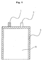
- Fig. 1 and Fig. 2 are schematic views illustrating basic constructions of polymer batteries produced in the present invention.
- a polymer battery 8 is composed mainly of a positive electrode 5, an electrolyte layer 6, a negative electrode 7 and a package 4. Further, reference numeral 1 denotes a terminal of the negative electrode 7, 2 a terminal of the positive electrode 5 and 3 a sealing member of the package 4.
- PVDF Polyvinylidene fluoride
- (d002) was 0.336 nm
- (Lc) was 100 nm
- (La) was 97 nm by X-ray wide-angle diffraction analysis and whose specific surface area was 2 m 2 /g by the BET method.
- NMP N-methyl-2-pyrrolidone
- the polymer fiber contained in the electrolyte layer was a nonwoven textile of polyester having a gas permeability of 380 sec/cm 3 , an area of 10 cm 2 and a thickness of 20 ⁇ m.
- the polymer fiber which formed a composite with the precursors of the ion-conductive compounds was laminated on the negative electrode which formed a composite with the precursors of the ion-conductive compounds.
- the resulting laminate was irradiated from above with an ultraviolet ray of 350 nm wavelength at an intensity of 30 mW/cm 2 for three minutes. At this time, the weight ratio of the ion-conductive compounds to the polymer fiber was 90 : 10.
- the resulting composite of the negative electrode, the polymer fiber and the ion-conductive compounds was bonded to the composite of the positive electrode and the ion-conductive compounds to produce a battery using the ion-conductive compounds.
- the total thickness of these positive electrode layer/electrolyte layer/negative electrode layer was 190 ⁇ m.
- PVDF as a binder 9 wt%, was mixed with artificial graphite particles whose (d002) was 0.337 nm, (Lc) was 100 nm and (La) was 100 nm by X-ray wide-angle diffraction analysis and whose specific surface area was 10 m 2 /g by the BET method.
- NMP was admixed and dissolved to give a paste. The paste was coated onto a rolled copper foil of 20 ⁇ m thickness, dried and pressed to give a negative electrode. The area of this electrode was 9 cm 2 and its thickness was 83 ⁇ m.
- the electrolyte layer and the battery were also made in the same manner as in Example 1.
- the total thickness of the obtained positive electrode layer/electrolyte layer/negative electrode layer was 188 ⁇ m.
- Example 1 and Comparative Example 1 were charged at a constant current of 2.3 mA until they reached a battery voltage of 4.1 V. After they reached 4.1 V, the batteries were charged at the constant current for the total charge time of 12 hours. The batteries were discharged at a constant current of 2.3 mA until they reached a battery voltage of 2.75 V. The cycle characteristics of the batteries were evaluated under these charge/discharge conditions. The results are shown in Fig. 3.
- the battery using the carbon material having the amorphous carbon attached to the surface thereof is excellent in the cycle characteristics since the decomposition of the ion-conductive compound in the electrolyte layer and the destroy of the negative electrode/electrolyte layer interface is suppressed better.
- PVDF as a binder 7 wt%, was mixed with carbon material particles having amorphous carbon attached to the surface thereof whose (d002) was 0.337 nm, (Lc) was 100 nm and (La) was 95 nm by X-ray wide-angle diffraction analysis and whose specific surface area was 5 m 2 /g by the BET method.
- NMP was admixed and dissolved to give a paste. The paste was coated onto an electrolytic copper foil of 18 ⁇ m thickness, dried and pressed to give a negative electrode. The area of this electrode was 9 cm 2 and its thickness was 80 ⁇ m.
- the polymer fiber contained in the electrolyte layer was a nonwoven textile of polypropylene (PP) having a gas permeability of 250 sec/cm 3 , an area of 10 cm 2 and a thickness of 20 ⁇ m.
- PP polypropylene
- An electrolyte was prepared in which 13 wt% of LiPF 6 was dissolved in a mixed solvent of EC and EMC (the EC content : 35 wt%).
- the negative electrode, the positive electrode and the polymer fiber were allowed to stand under reduced pressure for five minutes.
- the above-described mixed solution of the electrolyte and the precursor compound K 4 was poured thereon and allowed to stand for another five minutes.
- the polymer fiber which formed a composite with the precursor of the ion-conductive compound and the electrolyte was laminated on the negative electrode which formed a composite with the precursor of the ion-conductive compound and the electrolyte.
- the resulting laminate was irradiated from above with an ultraviolet ray of 350 nm wavelength at an intensity of 40 mW/cm 2 for three minutes. At this time, the weight ratio of the ion-conductive compound to the polymer fiber was 85 : 15.
- the positive electrode which formed a composite with the precursor of the ion-conductive compound and the electrolyte was irradiated from above with an ultraviolet ray of 350 nm wavelength at an intensity of 40 mW/cm 2 for three minutes.
- the resulting composite of the negative electrode, the polymer fiber and the ion-conductive gel was bonded to the composite of the positive electrode and the ion-conductive gel to produce a battery using the ion-conductive compound.
- the total thickness of these positive electrode layer/electrolyte layer/negative electrode layer was 190 ⁇ m.
- the polymer fiber contained in the electrolyte and the positive electrode the same ones as used in Example 2 were used.
- the negative electrode, the polymer fiber and the positive electrode were separately formed into composites with an ion-conductive gel whose precursor was the same as the precursor compound K 4 in Example 2.
- the composites were bonded to each other to produce a battery using the ion-conductive compound.
- the total thickness of these positive electrode layer/electrolyte layer/negative electrode layer was 195 ⁇ m.
- the polymer fiber was not contained in the electrolyte layer.
- the negative electrode and the positive electrode were separately formed into composites with an ion-conductive gel whose precursor was the same as the precursor compound K 4 in Example 2.
- the negative electrode and the positive electrode having formed the composites with the ion-conductive gel were bonded to each other to produce a battery using the ion-conductive compound.
- the total thickness of these positive electrode layer/electrolyte layer/negative electrode layer was 170 ⁇ m.
- Example 2 and Comparative Examples 2 and 3 were charged at a constant current of 2.3 mA until they reached a battery voltage of 4.1 V. After they reached 4.1 V, the batteries were charged at the constant current for the total charge time of 12 hours. The batteries were discharged at constant currents of 2.3 mA, 5 mA, 10 mA and 20 mA until they reached a battery voltage of 2.75 V. The results of a charge/discharge test under the above conditions are shown in Fig. 4.
- the thickness of the ion-conductive compound layer can be reduced, but the mechanical strength weakens and the battery is liable to short-circuit.
- PVDF as a binder 7 wt%, was mixed with carbon material particles having amorphous carbon attached to the surface thereof whose (d002) was 0.339 nm, (Lc) was 60 nm and (La) was 40 nm by X-ray wide-angle diffraction analysis and whose specific surface area was 5 m 2 /g by the BET method.
- NMP was admixed and dissolved to give a paste. The paste was coated onto an electrolytic copper foil of 18 ⁇ m thickness, dried and pressed to give a negative electrode. The area of this electrode was 9 cm 2 and its thickness was 85 ⁇ m.
- the polymer fiber contained in the electrolyte layer was a nonwoven textile of polyester having a gas permeability of 490 sec/cm 3 , an area of 10 cm 2 and a thickness of 25 ⁇ m.
- An electrolyte was prepared in which 15 wt% of LiN(CF 3 O 2 ) 2 was dissolved in a mixed solvent of EC and DMC (the EC content : 20 wt%).
- the electrolyte was mixed with a precursor of an ion-conductive compound with an average molecular weight of 7500 to 9000 which was the same as the precursor compound K 4 in Example 2 in a weight ratio of 95 : 5.
- the negative electrode, the positive electrode and the polymer fiber were allowed to stand under reduced pressure for two minutes.
- the above-described mixed solution was poured thereon and allowed to stand for another fifteen minutes.
- the polymer fiber which formed a composite with the precursor of the ion-conductive compound and the electrolyte was laminated on the negative electrode which formed a composite with the precursor of the ion-conductive compound and the electrolyte.
- the resulting laminate was irradiated from above with an ultraviolet ray of 360 nm wavelength at an intensity of 40 mW/cm 2 for two minutes. At this time, the weight ratio of the ion-conductive compound to the polymer fiber was 50 : 50.
- the positive electrode which formed a composite with the precursor of the ion-conductive compound and the electrolyte was from above irradiated with an ultraviolet ray of 350 nm wavelength at an intensity of 40 mW/cm 2 for two minutes.
- the resulting composite of the negative electrode, the polymer fiber and the ion-conductive gel was bonded to the composite of the positive electrode and the ion-conductive gel to produce a battery using the ion-conductive compound.
- the total thickness of these positive electrode layer/electrolyte layer/negative electrode layer was 195 ⁇ m.
- a battery was produced in the same manner as in Example 3 except that the gas permeability of a nonwoven textile of polyester in the electrolyte layer was 510 sec/cm 3 and the weight ratio of the ion-conductive compound and the polymer fiber was 97 : 3.
- a battery was produced in the same manner as in Example 3 except that the polymer fiber in the electrolyte layer is a nonwoven textile of PP having a gas permeability of 0.5 sec/cm 3 , an area of 10 cm 2 and a thickness of 20 ⁇ m and the weight ratio of the ion-conductive compound to the polymer fiber was 40 : 60.
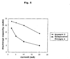
- Example 3 and Comparative Examples 4 and 5 were charged at a constant current of 2.1 mA until they reached a battery voltage of 4.1 V. After they reached 4.1 V, the batteries were charged at the constant voltage for the total charge time of 12 hours. The batteries were discharged at constant currents of 2.1 mA, 5 mA, 10 mA and 20 mA until they reached a battery voltage of 2.75 V. The results of a charge/discharge test under these conditions are shown in Fig. 5.
- PVDF as a binder 7 wt%, was mixed with carbon material particles having amorphous carbon attached to the surface thereof whose (d002) was 0.338 nm, (Lc) was 100 nm and (La) was 100 nm by X-ray wide-angle diffraction analysis and whose specific surface area was 3 m 2 /g by the BET method.
- NMP was admixed and dissolved to give a paste. The paste was coated onto an electrolytic copper foil of 18 ⁇ m thickness, dried and pressed to give a negative electrode. The area of this electrode was 9 cm 2 and its thickness was 83 ⁇ m.
- the polymer fiber contained in the electrolyte layer was a nonwoven textile of PP having a gas permeability of 350 sec/cm 3 , an area of 10 cm 2 and a thickness of 20 ⁇ m.
- An electrolyte was prepared in which 12 wt% of LiBF 4 was dissolved in a mixed solvent of EC and EMC (the EC content : 55 wt%).
- the electrolyte was mixed with a precursor of an ion-conductive compound with an average molecular weight of 7500 to 9000 which was the same as the precursor compound K 4 in Example 2 in a weight ratio of 95 : 5.
- the negative electrode, the positive electrode and the polymer fiber were allowed to stand under reduced pressure for two minutes.
- the above-described mixed solution was poured thereon, and allowed to stand for another fifteen minutes.
- the polymer fiber which formed a composite with the precursor of the ion-conductive compound and the electrolyte was laminated on the negative electrode which formed a composite with the precursor of the ion-conductive compound and the electrolyte.
- the resulting laminate was irradiated from above with an ultraviolet ray of 360 nm wavelength at an intensity of 40 mW/cm 2 for two minutes. At this time, the weight ratio of the ion-conductive compound to the polymer fiber was 75 : 25.
- the positive electrode which formed a composite with the precursor of the ion-conductive compound and the above-described electrolyte was irradiated from above with an ultraviolet ray of 355 nm wavelength at an intensity of 40 mW/cm 2 for two minutes.
- the resulting composite of the negative electrode, the polymer fiber and the ion-conductive gel was bonded to the composite of the positive electrode and the ion-conductive gel to produce a battery using the ion-conductive compound.
- the total thickness of these positive electrode layer/electrolyte layer/negative electrode layer was 185 ⁇ m.
- a battery similar to that of Example 4 was produced except that, in the electrolyte, 14 wt% of LiBF 4 was dissolved in a mixed solvent of EC and GBL (the EC content : 35 wt%).
- a battery similar to that of Example 4 was produced except that, in the electrolyte, 13 wt% of LiBF 4 was dissolved in a mixed solvent of EC and DEC (the EC content : 30 wt%).
- a battery similar to that of Example 4 was produced except that, in the electrolyte, 12 wt% of LiPF 6 was dissolved in a mixed solvent of EC and DMC (the EC content : 60 wt%).
- the batteries of Examples 4 to 7 and Comparative Example 6 were charged at a constant current of 2.0 mA until they reached a battery voltage of 4.1 V. After they reached 4.1 V, the batteries were charged at the constant voltage for the total charge time of 12 hours. The batteries were discharged at constant current of 2.0 mA until they reached a battery voltage of 2.75 V. The initial discharge was carried out at a temperature of 25 °C and the second discharge was carried out at a temperature of - 20 °C-.
- the following tables show the ratio of the second discharge capacity to the first discharge capacity.
- Example 2 0/10 Comparative Example 2 0/10 Comparative Example 3 7/10 Number of Short Circuits at First Charge
- Example 6 0/10 Comparative Example 4 5/10 Comparative Example 5 0/10 First Discharge Capacity (mAh) (Second (-20°C) Discharge Capacity) / (First Discharge Capacity)
- Example 4 23 0.33
- Example 5 22 0.65
- Example 7 22 0.62 Comparative Example 6 23 0.08
- PVDF as a binder, 9 parts by weight, was mixed with 100 parts by weight of carbon material particles comprising graphite particles having amorphous carbon attached to the surface thereof whose (d002) was 0.336 nm, (Lc) was 100 nm and (La) was 97 nm by X-ray wide-angle diffraction analysis and whose specific surface area was 2 m 2 /g by the BET method.
- NMP was admixed and dissolved to give a paste. The paste was coated onto a rolled copper foil of 20 ⁇ m thickness, dried and pressed to give a negative electrode. The area of this electrode was 9 cm 2 and its thickness was 85 ⁇ m.
- the electrolyte was mixed with the following compounds K 5 and K 6 which were precursors of ion-conductive polymers in a weight ratio of 90 : 5 : 5.
- DMPA 1000 ppm was added to prepare a polymerization liquid.
- the above-mentioned negative electrode was allowed to stand under reduced pressure for five minutes and the above-described mixed solution was poured onto the negative electrode, which was then allowed to stand for another 15 minutes.
- the electrolyte was mixed with the compounds K 5 and K 6 which were precursors of ion-conductive polymers in a weight ratio of 90 : 5 : 5.
- DMPA 1000 ppm was added to prepare a polymerization liquid.
- the fibrous organic compound having formed a composite with the precursors of the ion-conductive polymers was laminated on the negative electrode.
- the laminated was irradiated from above with an ultraviolet ray of 365 nm wavelength at an intensity of 30 mW/cm 2 for three minutes.
- the weight ratio of the ion-conductive polymers to the fibrous organic compound was 90 : 10.
- an ion-conductive polymer was formed in a gel state to be integrated with the negative electrode and the fibrous organic compound.
- the thus obtained ion-conductive polymer layer was 20 ⁇ m thick.
- the electrolyte was mixed with the compounds K 5 and K 6 which were precursors of ion-conductive polymers in a weight ratio of 90 : 5 : 5.
- DMPA 1000 ppm was added to prepare a polymerization liquid.
- the above-described positive electrode was allowed to stand under reduced pressure for five minutes.
- the above mixed solution was poured onto the positive electrode, cast and allowed to stand for another five minutes.
- the positive electrode with nothing put on, was irradiated with an ultraviolet ray of 365 nm wavelength at an intensity of 30 mW/cm 2 for three minutes. Thereby an ion-conductive polymer was formed in a gel state to be integrated with the positive electrode.
- the thus obtained ion-conductive polymer layer was 10 ⁇ m thick.
- Example 8 A battery of Example 8 was produced by bonding the (ion-conductive polymer + fibrous organic compound) layer / the negative electrode / the negative electrode collector obtained in b) to the positive electrode collector / the positive electrode / the ion-conductive polymer layer obtained in a). The total thickness of these positive electrode layer / electrolyte layer / negative electrode layer was 190 ⁇ m.
- a battery of Example 9 was produced in the same manner as in Example 8 except that the compound K 6 in Example 8 was replaced with the following compound K 7 .
- the total thickness of the positive electrode layer / electrolyte layer / negative electrode layer was 190 ⁇ m.
- a battery of Example 10 was produced in the same manner as in Example 8 except that the compound K 6 in Example 8 was replaced with the following compound K 8 .
- the total thickness of the positive electrode layer / electrolyte layer / negative electrode layer was 190 ⁇ m.
- the total thickness of the positive electrode layer / electrolyte layer / negative electrode layer was 190 ⁇ m.
- the total thickness of the positive electrode layer / electrolyte layer / negative electrode layer was 190 ⁇ m.
- the batteries of Examples 2, 8 to 11 and Comparative Example 7 were charged at a constant current of 2.3 mA until they reached a battery voltage of 4.1 V. After they reached 4.1 V, the batteries were charged at the constant voltage for the total charge time of 12 hours. The batteries were discharged at a constant current of 2.3 mA and 10 mA until they reached a battery voltage of 2.75 V.
- Fig.5 shows the discharge capacity and the charge/discharge efficiency at the first cycle when the discharge was conducted under the above conditions.
- Example 2 Discharge Capacity Charge/Discharge Efficiency at First Cycle 2.3mA discharge 10mA discharge
- Example 2 24.0 mAh 21.9 mAh 82 %
- Example 8 24.1 mAh 22.4 mAh 83 %
- Example 9 24.2 mAh 22.4 mAh 84 %
- Example 10 24.0 mAh 22.0 mAh 82 %
- Example 11 24.1 mAh 22.3 mAh 84 % Comparative Example 7 15.7 mAh 5.2 mAh 52 %
- a precursor of an ion-conductive polymer constituted of acrylate is more preferable than one constituted of methacrylate.
- the battery in which the carbon material of the present invention and the ion-conductive polymer are combined solves the problem as reported with conventional graphite type carbon materials that the presence only of 10 % PC in the electrolyte induces the decomposition of PC remarkably and renders charge/discharge operation impossible.
- a polymer battery comprising a negative electrode comprising at least a carbon material as an active material, an electrolyte layer and a positive electrode comprising at least a lithium-containing chalcogenide as an active material, wherein the electrolyte layer contains an ion-conductive compound and a polymer fiber, and the carbon material comprises graphite particles having amorphous carbon attached to the surface thereof, it has become possible to suppress the decomposition of the ion-conductive compound caused by charge and discharge, and as a result, to eliminate the short circuit, expansion and leakage of the battery and improve the reliability of the battery.
- the material for positive electrodes of the present invention it has become possible to reduce the amount of the EC component in the ion-conductive compound and produce a battery which can exhibit excellent charge/discharge characteristics at low temperatures.
- the battery when the battery is produced, by including the precursor of the ion-conductive compound beforehand in the above-mentioned negative electrode and positive electrode and crosslinking the precursor with the precursor of the ion-conductive compound in the electrolyte layer, it is possible to reduce the number of interfaces between, the electrodes and the electrolyte.
- the internal resistance of the battery can be reduced, and the battery can be produced to be excellent in high load discharge characteristics and high-speed charge characteristics.
- the electrode and electrolyte can be integrally formed and the productivity of the battery can be improved.
- the precursor of the ion-conductive compound of the present invention is a mono-functional, di-functional or tri-functional acrylate
- the crosslinking reaction shows a high degree of reaction. Accordingly, the precursor does not remain unreacted within the electrode or at the interface, and consequently, side reaction on the electrodes can be suppressed and the battery can be produced to have good cycle characteristics and high reliability.
Landscapes
- Chemical & Material Sciences (AREA)
- Chemical Kinetics & Catalysis (AREA)
- Electrochemistry (AREA)
- General Chemical & Material Sciences (AREA)
- Engineering & Computer Science (AREA)
- Manufacturing & Machinery (AREA)
- Inorganic Chemistry (AREA)
- Composite Materials (AREA)
- Dispersion Chemistry (AREA)
- Physics & Mathematics (AREA)
- General Physics & Mathematics (AREA)
- Condensed Matter Physics & Semiconductors (AREA)
- Secondary Cells (AREA)
- Battery Electrode And Active Subsutance (AREA)
- Carbon And Carbon Compounds (AREA)
Abstract
Description


| Number of Short Circuits at First Charge | |
| Example 2 | 0/10 |
| Comparative Example 2 | 0/10 |
| Comparative Example 3 | 7/10 |
| Number of Short Circuits at First Charge | |
| Example 6 | 0/10 |
| Comparative Example 4 | 5/10 |
| Comparative Example 5 | 0/10 |
| First Discharge Capacity (mAh) | (Second (-20°C) Discharge Capacity) / (First Discharge Capacity) | |
| Example 4 | 23 | 0.33 |
| Example 5 | 22 | 0.65 |
| Example 6 | 23 | 0.50 |
| Example 7 | 22 | 0.62 |
| Comparative Example 6 | 23 | 0.08 |


| Discharge Capacity | Charge/Discharge Efficiency at First Cycle | ||
| 2.3mA discharge | 10mA discharge | ||
| Example 2 | 24.0 mAh | 21.9 mAh | 82 % |
| Example 8 | 24.1 mAh | 22.4 mAh | 83 % |
| Example 9 | 24.2 mAh | 22.4 mAh | 84 % |
| Example 10 | 24.0 mAh | 22.0 mAh | 82 % |
| Example 11 | 24.1 mAh | 22.3 mAh | 84 % |
| Comparative Example 7 | 15.7 mAh | 5.2 mAh | 52 % |
Claims (12)
- A polymer battery comprising:characterized in that the electrolyte layer contains an ion-conductive compound and a polymer fiber, and the carbon material comprises graphite particles having amorphous carbon attached to the surface thereof.a negative electrode comprising at least a carbon material as an active material;an electrolyte layer; anda positive electrode comprising at least a lithium-containing chalcogenide as an active material,
- A polymer battery as set forth in claim 1, characterized in that the negative electrode and the positive electrode contain the same ion-conductive compound as the electrolyte layer contains, the ion-conductive compound in the negative electrode, the positive electrode and the electrolyte layer are formed by crosslinking corresponding precursors, and the crosslinking of the precursor of the ion-conductive compound in the electrolyte layer is carried out together with the crosslinking of the precursor of the ion-conductive compound contained in the negative and/or positive electrode.
- A polymer battery as set forth in claim 2, characterized in that the positive electrode, the negative electrode and the electrolyte layer form a single composite obtained by including the precursor of the ion-conductive compound beforehand in the polymer fiber of the electrolyte layer, the positive electrode and the negative electrode and crosslinking the precursor by applying an ultraviolet ray onto the polymer fiber, the positive electrode and the negative electrode.
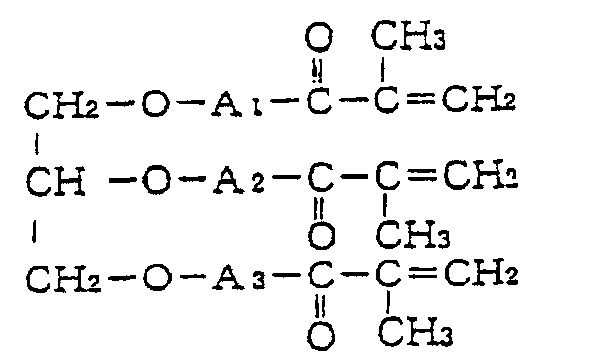
- A polymer battery as set forth in any one of claims 1 to 3, characterized in that the electrolyte layer further comprises a Li salt and the ion-conductive compound is a crosslinked substance obtained by crosslinking at least one of precursors of ion-conductive compounds represented by the following formulae:(wherein R1 is a hydrogen atom or methyl group, A1, A2 and A3 are bivalent residues having at least three ethylene oxide units (EO) or having (an) ethylene oxide unit(s) (EO) and (a) propylene oxide unit(s) (PO), and the numbers of PO and EO satisfy PO/EO = 0 to 5),
 (wherein R2 and R3 are independently a hydrogen atom or methyl group, A4 is a bivalent residue having at least three ethylene oxide units (EO) or having (an) ethylene oxide unit(s) (EO) and (a) propylene oxide unit(s) (PO), and the numbers of PO and EO satisfy PO/EO = 0 to 5),
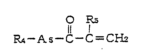
 (wherein R4 and R5 are independently a hydrogen atom or a methyl group, A5 is a bivalent residue having at least three ethylene oxide units (EO) or having (an) ethylene oxide unit(s) (EO) and (a) propylene oxide unit(s) (PO), and the numbers of PO and EO satisfy PO/EO = 0 to 5).
- A polymer battery as set forth in any one of claims 1 to 3, characterized in that the electrolyte layer further comprises a Li salt and the ion-conductive compound is a crosslinked substance obtained by crosslinking at least one of precursors of ion-conductive compounds represented by the following formulae:(wherein R1' is a hydrogen atom or a lower alkyl group having a carbon number of 1 or more, A1, A2 and A3 are bivalent residues having at least three ethylene oxide units (EO) or having (an) ethylene oxide unit(s) (EO) and (a) propylene oxide unit(s) (PO), and the numbers of PO and EO satisfy PO/EO = 0 to 5 and EO + PO ≧ 10),
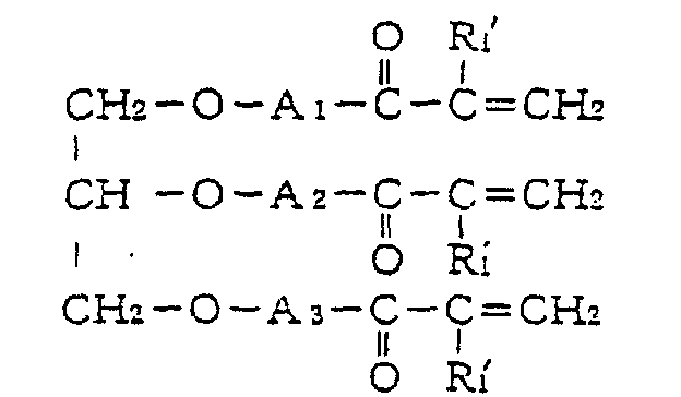 (wherein R2' and R3' are independently a hydrogen atom or a lower alkyl group having a carbon number of 1 or more, A4 is a bivalent residue having at least three ethylene oxide units (EO) or having (an) ethylene oxide unit(s) (EO) and (a) propylene oxide unit(s) (PO), and the numbers of PO and EO satisfy PO/EO = 0 to 5 and EO + PO ≧ 10),
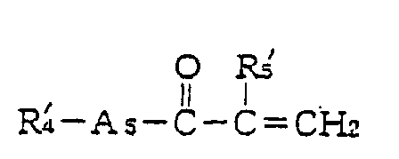
 (wherein R4' and R5' are independently a hydrogen atom or a lower alkyl group having a carbon number of 1 or more, A5 is a bivalent residue having at least three ethylene oxide units (EO) or having (an) ethylene oxide unit(s) (EO) and (a) propylene oxide unit(s) (PO), and the numbers of PO and EO satisfy PO/EO = 0 to 5 and EO + PO ≧ 3).
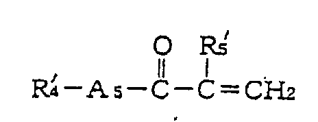
- A polymer battery as set forth in claim 4 or 5, characterized in that the electrolyte layer contains an organic electrolyte in which at least one Li salt selected from LiBF4, LiPF6 and LiN(CF3SO2)2 is dissolved in a mixed organic solvent composed of ethylene carbonate and at least one solvent selected from propylene carbonate, γ-butyrolactone, ethylmethyl carbonate, dimethyl carbonate and diethyl carbonate.
- A polymer battery as set forth in claim 6, characterized in that the weight ratio of the ion-conductive compound to the organic electrolyte is within a range from 30 : 70 to 2 : 98.
- A polymer battery as set forth in claim 6 or 7, characterized in that the content of ethylene carbonate in the organic electrolyte is at least 2 to 55 wt% and the content of the Li salt is at least 3 to 35 wt%.
- A polymer battery as set forth in any one of claims 1 to 8, characterized in that the polymer fiber comprises at least one of polypropylene fiber, polyethylene fiber and polyester fiber.
- A polymer battery as set forth in claim 9, characterized in that the polymer fiber is a nonwoven textile having a gas permeability of 1 to 500 sec/cm3.
- A polymer battery as set forth in any one of claims 1 to 10, characterized in that the weight ratio of the ion-conductive compound to the polymer fiber in the electrolyte layer is within a range from 91 : 1 to 50 : 50.
- A polymer battery as set forth in any one of claims 1 to 11, characterized in that the graphite particles having amorphous carbon attached to the surface thereof have an average interplanar distance (d002) in plane (002) of 0.335 to 0.340 nm, a crystalline unit battery thickness (Lc) in a direction of plane (002) of 10 nm or more (more preferably, 40 nm or more), a crystalline unit battery thickness (La) in a direction of plane (110) is 10 nm or more and a specific surface area of 5 m2/g or less.
Applications Claiming Priority (5)
| Application Number | Priority Date | Filing Date | Title |
|---|---|---|---|
| JP33024599 | 1999-11-19 | ||
| JP33024599 | 1999-11-19 | ||
| JP2000324111A JP4751502B2 (en) | 1999-11-19 | 2000-10-24 | Polymer battery |
| JP2000324111 | 2000-10-24 | ||
| PCT/JP2000/008142 WO2001039315A1 (en) | 1999-11-19 | 2000-11-17 | Polymer cell |
Publications (4)
| Publication Number | Publication Date |
|---|---|
| EP1265307A1 true EP1265307A1 (en) | 2002-12-11 |
| EP1265307A4 EP1265307A4 (en) | 2006-11-29 |
| EP1265307B1 EP1265307B1 (en) | 2008-08-06 |
| EP1265307B9 EP1265307B9 (en) | 2008-12-03 |
Family
ID=26573469
Family Applications (1)
| Application Number | Title | Priority Date | Filing Date |
|---|---|---|---|
| EP00976340A Expired - Lifetime EP1265307B9 (en) | 1999-11-19 | 2000-11-17 | Polymer cell |
Country Status (8)
| Country | Link |
|---|---|
| US (1) | US7311998B1 (en) |
| EP (1) | EP1265307B9 (en) |
| JP (1) | JP4751502B2 (en) |
| KR (1) | KR100462668B1 (en) |
| CN (1) | CN1213501C (en) |
| DE (1) | DE60039789D1 (en) |
| TW (1) | TW494599B (en) |
| WO (1) | WO2001039315A1 (en) |
Cited By (3)
| Publication number | Priority date | Publication date | Assignee | Title |
|---|---|---|---|---|
| EP1329976A4 (en) * | 2000-09-29 | 2007-03-21 | Sharp Kk | Lithium secondary cell |
| EP1652250A4 (en) * | 2003-07-22 | 2007-10-17 | Byd Co Ltd | Improved graphite granules and their method of fabrication |
| EP2792637A4 (en) * | 2011-12-16 | 2015-08-19 | Jfe Chemical Corp | PROCESS FOR PRODUCING AMORPHOUS CARBON PARTICLES, AMORPHOUS CARBON PARTICLES, NEGATIVE ELECTRODE MATERIAL FOR LITHIUM BATTERIES, AND LITHIUM BATTERIES |
Families Citing this family (13)
| Publication number | Priority date | Publication date | Assignee | Title |
|---|---|---|---|---|
| JP3844931B2 (en) * | 2000-02-10 | 2006-11-15 | 東洋炭素株式会社 | Negative electrode and secondary battery |
| JP3976529B2 (en) * | 2001-09-18 | 2007-09-19 | シャープ株式会社 | Lithium polymer secondary battery and manufacturing method thereof |
| JP4336087B2 (en) * | 2002-09-19 | 2009-09-30 | シャープ株式会社 | Lithium polymer battery and manufacturing method thereof |
| JP4381023B2 (en) * | 2003-04-09 | 2009-12-09 | ソニー株式会社 | Secondary battery |
| JP2006339011A (en) * | 2005-06-01 | 2006-12-14 | Hitachi Ltd | Lithium ion secondary battery |
| US20090061321A1 (en) * | 2007-08-31 | 2009-03-05 | Fmc Corporation, Lithium Division | Stabilized lithium metal powder for li-ion application, composition and process |
| US9450246B2 (en) | 2009-10-27 | 2016-09-20 | Hitachi Chemical Company, Ltd. | Carbon particles for negative electrode of lithium ion secondary battery, negative electrode for lithium ion secondary battery, and lithium ion secondary battery |
| KR101463648B1 (en) * | 2011-06-30 | 2014-11-19 | 주식회사 엘지화학 | positive-electrode active material with improved OUTPUT and Lithium secondary battery including them |
| DE102012200862A1 (en) * | 2012-01-23 | 2013-07-25 | Robert Bosch Gmbh | Battery production by spin coating |
| WO2017057123A1 (en) * | 2015-09-30 | 2017-04-06 | Necエナジーデバイス株式会社 | Negative electrode for lithium ion secondary batteries and lithium ion secondary battery |
| JP6876648B2 (en) * | 2018-03-22 | 2021-05-26 | 株式会社東芝 | Rechargeable batteries, battery packs and vehicles |
| JP7262492B2 (en) * | 2021-01-13 | 2023-04-21 | プライムプラネットエナジー&ソリューションズ株式会社 | Negative electrode active material, lithium ion battery, and method for producing negative electrode active material |
| CN119092707B (en) * | 2024-08-26 | 2025-11-25 | 厦门海辰储能科技股份有限公司 | Semi-solid batteries, energy storage devices and electrical equipment |
Family Cites Families (20)
| Publication number | Priority date | Publication date | Assignee | Title |
|---|---|---|---|---|
| FR2442512A1 (en) | 1978-11-22 | 1980-06-20 | Anvar | NEW ELASTOMERIC MATERIALS WITH ION CONDUCTION |
| US4547440A (en) | 1983-04-22 | 1985-10-15 | United Kingdom Atomic Energy Authority | Electrochemical cell |
| GB8412304D0 (en) | 1984-05-14 | 1984-06-20 | Atomic Energy Authority Uk | Composite cathode |
| JP2884746B2 (en) | 1990-09-03 | 1999-04-19 | 松下電器産業株式会社 | Non-aqueous electrolyte secondary battery |
| US5153082A (en) | 1990-09-04 | 1992-10-06 | Bridgestone Corporation | Nonaqueous electrolyte secondary battery |
| JP2643035B2 (en) * | 1991-06-17 | 1997-08-20 | シャープ株式会社 | Carbon negative electrode for non-aqueous secondary battery and method for producing the same |
| US5275750A (en) | 1991-07-18 | 1994-01-04 | Matsushita Electric Industrial Co., Ltd. | Method of manufacturing a solid polymer electrolyte |
| US5268243A (en) * | 1992-01-27 | 1993-12-07 | Dai-Ichi Kogyo Seiyaku Co., Ltd. | Galvanic cell |
| JPH05335005A (en) * | 1992-06-02 | 1993-12-17 | Asahi Chem Ind Co Ltd | Separator |
| DE69514711T2 (en) * | 1994-05-12 | 2000-05-31 | Ube Industries, Ltd. | Porous multilayer film |
| JP3340337B2 (en) | 1997-01-30 | 2002-11-05 | シャープ株式会社 | Non-aqueous secondary battery and method for producing negative electrode active material |
| JPH10208544A (en) * | 1997-01-22 | 1998-08-07 | Ricoh Co Ltd | Polymer solid electrolyte and battery using the same |
| JP3633257B2 (en) * | 1997-02-04 | 2005-03-30 | 三菱化学株式会社 | Lithium ion secondary battery |
| JP3458049B2 (en) * | 1997-04-25 | 2003-10-20 | 株式会社リコー | Ion conductive polymer solid electrolyte and electrochemical device containing the solid electrolyte |
| KR100483126B1 (en) | 1997-05-30 | 2005-04-14 | 마츠시타 덴끼 산교 가부시키가이샤 | Nonaqueous electrolyte secondary battery |
| JP3607470B2 (en) * | 1997-09-12 | 2005-01-05 | 株式会社リコー | Polymer battery |
| EP0903799B1 (en) * | 1997-09-19 | 2003-03-12 | Matsushita Electric Industrial Co., Ltd. | Nonaqueous electrolyte secondary battery and its anode |
| JP4005192B2 (en) | 1997-12-09 | 2007-11-07 | 第一工業製薬株式会社 | Solid battery |
| JPH11238503A (en) * | 1998-02-20 | 1999-08-31 | Yuasa Corp | Nonaqueous electrolyte secondary battery |
| GB9806831D0 (en) | 1998-03-30 | 1998-05-27 | Danionics As | Polymer electrolyte electrochemical cell |
-
2000
- 2000-10-24 JP JP2000324111A patent/JP4751502B2/en not_active Expired - Fee Related
- 2000-11-17 WO PCT/JP2000/008142 patent/WO2001039315A1/en not_active Ceased
- 2000-11-17 EP EP00976340A patent/EP1265307B9/en not_active Expired - Lifetime
- 2000-11-17 DE DE60039789T patent/DE60039789D1/en not_active Expired - Lifetime
- 2000-11-17 KR KR10-2002-7006336A patent/KR100462668B1/en not_active Expired - Fee Related
- 2000-11-17 US US10/130,961 patent/US7311998B1/en not_active Expired - Fee Related
- 2000-11-17 CN CNB008159688A patent/CN1213501C/en not_active Expired - Fee Related
- 2000-11-17 TW TW089124420A patent/TW494599B/en not_active IP Right Cessation
Cited By (3)
| Publication number | Priority date | Publication date | Assignee | Title |
|---|---|---|---|---|
| EP1329976A4 (en) * | 2000-09-29 | 2007-03-21 | Sharp Kk | Lithium secondary cell |
| EP1652250A4 (en) * | 2003-07-22 | 2007-10-17 | Byd Co Ltd | Improved graphite granules and their method of fabrication |
| EP2792637A4 (en) * | 2011-12-16 | 2015-08-19 | Jfe Chemical Corp | PROCESS FOR PRODUCING AMORPHOUS CARBON PARTICLES, AMORPHOUS CARBON PARTICLES, NEGATIVE ELECTRODE MATERIAL FOR LITHIUM BATTERIES, AND LITHIUM BATTERIES |
Also Published As
| Publication number | Publication date |
|---|---|
| JP4751502B2 (en) | 2011-08-17 |
| EP1265307B1 (en) | 2008-08-06 |
| US7311998B1 (en) | 2007-12-25 |
| DE60039789D1 (en) | 2008-09-18 |
| CN1213501C (en) | 2005-08-03 |
| KR20020053861A (en) | 2002-07-05 |
| CN1391708A (en) | 2003-01-15 |
| JP2001210380A (en) | 2001-08-03 |
| EP1265307A4 (en) | 2006-11-29 |
| WO2001039315A1 (en) | 2001-05-31 |
| EP1265307B9 (en) | 2008-12-03 |
| KR100462668B1 (en) | 2004-12-23 |
| TW494599B (en) | 2002-07-11 |
Similar Documents
| Publication | Publication Date | Title |
|---|---|---|
| JP4213687B2 (en) | Nonaqueous electrolyte battery and battery pack | |
| KR100782868B1 (en) | Charging method for charging nonaqueous electrolyte secondary battery | |
| US5744264A (en) | Lithium ion electrochemical cell | |
| CN103050707B (en) | Lithium rechargeable battery | |
| TWI387148B (en) | Anode and secondary battery | |
| JP5070753B2 (en) | battery | |
| KR101749508B1 (en) | Electrode active material for lithium secondary battery, electrode for lithium secondary battery including the same, and lithium secondary battery comprising the same | |
| JPH02265167A (en) | Nonaqueous electrolyte secondary battery | |
| JP3492173B2 (en) | Non-aqueous battery | |
| US20120202115A1 (en) | Anode active material, anode, battery, and method of manufacturing anode | |
| US7311998B1 (en) | Lithium polymer battery with a crosslinked electrolyte | |
| JP5412843B2 (en) | battery | |
| JP2021048135A (en) | Non-aqueous electrolyte for secondary batteries and non-aqueous electrolyte secondary batteries using it | |
| US20130078526A1 (en) | Separator for electrochemical device, method for producing the same, and electrochemical device | |
| JP2009164013A (en) | Negative electrode and battery | |
| US20190131623A1 (en) | Method for charging lithium-ion secondary battery, lithium-ion secondary battery system, and power storage device | |
| KR20080027136A (en) | battery | |
| JP2007258127A (en) | Negative electrode and battery | |
| US20240072252A1 (en) | Positive electrode for secondary battery, and secondary battery | |
| JPH11279785A (en) | Composite carbon material for electrode, its production and nonaqueous electrolytic solution secondary cell using that | |
| JP5082221B2 (en) | Negative electrode for secondary battery and secondary battery | |
| JP2002042874A (en) | Polymer secondary battery | |
| JP2001052742A (en) | Sheet secondary battery | |
| JP7753882B2 (en) | Nonaqueous electrolyte storage element and method for manufacturing same | |
| US20220209372A1 (en) | Battery module |
Legal Events
| Date | Code | Title | Description |
|---|---|---|---|
| PUAI | Public reference made under article 153(3) epc to a published international application that has entered the european phase |
Free format text: ORIGINAL CODE: 0009012 |
|
| 17P | Request for examination filed |
Effective date: 20020619 |
|
| AK | Designated contracting states |
Kind code of ref document: A1 Designated state(s): AT BE CH CY DE DK ES FI FR GB GR IE IT LI LU MC NL PT SE TR |
|
| RAP1 | Party data changed (applicant data changed or rights of an application transferred) |
Owner name: SHARP KABUSHIKI KAISHA Owner name: DAI-ICHI KOGYO SEIYAKU CO., LTD. |
|
| RBV | Designated contracting states (corrected) |
Designated state(s): AT BE CH DE FR GB LI |
|
| A4 | Supplementary search report drawn up and despatched |
Effective date: 20061030 |
|
| 17Q | First examination report despatched |
Effective date: 20070124 |
|
| GRAP | Despatch of communication of intention to grant a patent |
Free format text: ORIGINAL CODE: EPIDOSNIGR1 |
|
| GRAS | Grant fee paid |
Free format text: ORIGINAL CODE: EPIDOSNIGR3 |
|
| GRAA | (expected) grant |
Free format text: ORIGINAL CODE: 0009210 |
|
| RBV | Designated contracting states (corrected) |
Designated state(s): DE FR GB |
|
| AK | Designated contracting states |
Kind code of ref document: B1 Designated state(s): DE FR GB |
|
| REG | Reference to a national code |
Ref country code: GB Ref legal event code: FG4D |
|
| REF | Corresponds to: |
Ref document number: 60039789 Country of ref document: DE Date of ref document: 20080918 Kind code of ref document: P |
|
| PLBE | No opposition filed within time limit |
Free format text: ORIGINAL CODE: 0009261 |
|
| STAA | Information on the status of an ep patent application or granted ep patent |
Free format text: STATUS: NO OPPOSITION FILED WITHIN TIME LIMIT |
|
| 26N | No opposition filed |
Effective date: 20090507 |
|
| PGFP | Annual fee paid to national office [announced via postgrant information from national office to epo] |
Ref country code: DE Payment date: 20141126 Year of fee payment: 15 Ref country code: GB Payment date: 20141112 Year of fee payment: 15 |
|
| PGFP | Annual fee paid to national office [announced via postgrant information from national office to epo] |
Ref country code: FR Payment date: 20141201 Year of fee payment: 15 |
|
| REG | Reference to a national code |
Ref country code: DE Ref legal event code: R119 Ref document number: 60039789 Country of ref document: DE |
|
| GBPC | Gb: european patent ceased through non-payment of renewal fee |
Effective date: 20151117 |
|
| REG | Reference to a national code |
Ref country code: FR Ref legal event code: ST Effective date: 20160729 |
|
| PG25 | Lapsed in a contracting state [announced via postgrant information from national office to epo] |
Ref country code: GB Free format text: LAPSE BECAUSE OF NON-PAYMENT OF DUE FEES Effective date: 20151117 Ref country code: DE Free format text: LAPSE BECAUSE OF NON-PAYMENT OF DUE FEES Effective date: 20160601 |
|
| PG25 | Lapsed in a contracting state [announced via postgrant information from national office to epo] |
Ref country code: FR Free format text: LAPSE BECAUSE OF NON-PAYMENT OF DUE FEES Effective date: 20151130 |