EP1265218A1 - Environment compatible image display system, image processing method and information storing medium - Google Patents
Environment compatible image display system, image processing method and information storing medium Download PDFInfo
- Publication number
- EP1265218A1 EP1265218A1 EP01958567A EP01958567A EP1265218A1 EP 1265218 A1 EP1265218 A1 EP 1265218A1 EP 01958567 A EP01958567 A EP 01958567A EP 01958567 A EP01958567 A EP 01958567A EP 1265218 A1 EP1265218 A1 EP 1265218A1
- Authority
- EP
- European Patent Office
- Prior art keywords
- image
- information
- viewing environment
- brightness
- environment
- Prior art date
- Legal status (The legal status is an assumption and is not a legal conclusion. Google has not performed a legal analysis and makes no representation as to the accuracy of the status listed.)
- Ceased
Links
Images




Classifications
-
- H—ELECTRICITY
- H04—ELECTRIC COMMUNICATION TECHNIQUE
- H04N—PICTORIAL COMMUNICATION, e.g. TELEVISION
- H04N9/00—Details of colour television systems
- H04N9/12—Picture reproducers
- H04N9/31—Projection devices for colour picture display, e.g. using electronic spatial light modulators [ESLM]
- H04N9/3179—Video signal processing therefor
- H04N9/3182—Colour adjustment, e.g. white balance, shading or gamut
-
- G—PHYSICS
- G09—EDUCATION; CRYPTOGRAPHY; DISPLAY; ADVERTISING; SEALS
- G09G—ARRANGEMENTS OR CIRCUITS FOR CONTROL OF INDICATING DEVICES USING STATIC MEANS TO PRESENT VARIABLE INFORMATION
- G09G3/00—Control arrangements or circuits, of interest only in connection with visual indicators other than cathode-ray tubes
- G09G3/001—Control arrangements or circuits, of interest only in connection with visual indicators other than cathode-ray tubes using specific devices not provided for in groups G09G3/02 - G09G3/36, e.g. using an intermediate record carrier such as a film slide; Projection systems; Display of non-alphanumerical information, solely or in combination with alphanumerical information, e.g. digital display on projected diapositive as background
- G09G3/002—Control arrangements or circuits, of interest only in connection with visual indicators other than cathode-ray tubes using specific devices not provided for in groups G09G3/02 - G09G3/36, e.g. using an intermediate record carrier such as a film slide; Projection systems; Display of non-alphanumerical information, solely or in combination with alphanumerical information, e.g. digital display on projected diapositive as background to project the image of a two-dimensional display, such as an array of light emitting or modulating elements or a CRT
-
- G—PHYSICS
- G09—EDUCATION; CRYPTOGRAPHY; DISPLAY; ADVERTISING; SEALS
- G09G—ARRANGEMENTS OR CIRCUITS FOR CONTROL OF INDICATING DEVICES USING STATIC MEANS TO PRESENT VARIABLE INFORMATION
- G09G5/00—Control arrangements or circuits for visual indicators common to cathode-ray tube indicators and other visual indicators
- G09G5/02—Control arrangements or circuits for visual indicators common to cathode-ray tube indicators and other visual indicators characterised by the way in which colour is displayed
-
- G—PHYSICS
- G09—EDUCATION; CRYPTOGRAPHY; DISPLAY; ADVERTISING; SEALS
- G09G—ARRANGEMENTS OR CIRCUITS FOR CONTROL OF INDICATING DEVICES USING STATIC MEANS TO PRESENT VARIABLE INFORMATION
- G09G5/00—Control arrangements or circuits for visual indicators common to cathode-ray tube indicators and other visual indicators
- G09G5/02—Control arrangements or circuits for visual indicators common to cathode-ray tube indicators and other visual indicators characterised by the way in which colour is displayed
- G09G5/06—Control arrangements or circuits for visual indicators common to cathode-ray tube indicators and other visual indicators characterised by the way in which colour is displayed using colour palettes, e.g. look-up tables
-
- H—ELECTRICITY
- H04—ELECTRIC COMMUNICATION TECHNIQUE
- H04N—PICTORIAL COMMUNICATION, e.g. TELEVISION
- H04N17/00—Diagnosis, testing or measuring for television systems or their details
- H04N17/02—Diagnosis, testing or measuring for television systems or their details for colour television signals
-
- H—ELECTRICITY
- H04—ELECTRIC COMMUNICATION TECHNIQUE
- H04N—PICTORIAL COMMUNICATION, e.g. TELEVISION
- H04N5/00—Details of television systems
- H04N5/44—Receiver circuitry for the reception of television signals according to analogue transmission standards
- H04N5/57—Control of contrast or brightness
- H04N5/58—Control of contrast or brightness in dependence upon ambient light
-
- H—ELECTRICITY
- H04—ELECTRIC COMMUNICATION TECHNIQUE
- H04N—PICTORIAL COMMUNICATION, e.g. TELEVISION
- H04N9/00—Details of colour television systems
- H04N9/12—Picture reproducers
- H04N9/31—Projection devices for colour picture display, e.g. using electronic spatial light modulators [ESLM]
-
- H—ELECTRICITY
- H04—ELECTRIC COMMUNICATION TECHNIQUE
- H04N—PICTORIAL COMMUNICATION, e.g. TELEVISION
- H04N9/00—Details of colour television systems
- H04N9/12—Picture reproducers
- H04N9/31—Projection devices for colour picture display, e.g. using electronic spatial light modulators [ESLM]
- H04N9/3191—Testing thereof
- H04N9/3194—Testing thereof including sensor feedback
-
- H—ELECTRICITY
- H04—ELECTRIC COMMUNICATION TECHNIQUE
- H04N—PICTORIAL COMMUNICATION, e.g. TELEVISION
- H04N9/00—Details of colour television systems
- H04N9/64—Circuits for processing colour signals
-
- H—ELECTRICITY
- H04—ELECTRIC COMMUNICATION TECHNIQUE
- H04N—PICTORIAL COMMUNICATION, e.g. TELEVISION
- H04N9/00—Details of colour television systems
- H04N9/64—Circuits for processing colour signals
- H04N9/73—Colour balance circuits, e.g. white balance circuits or colour temperature control
-
- G—PHYSICS
- G09—EDUCATION; CRYPTOGRAPHY; DISPLAY; ADVERTISING; SEALS
- G09G—ARRANGEMENTS OR CIRCUITS FOR CONTROL OF INDICATING DEVICES USING STATIC MEANS TO PRESENT VARIABLE INFORMATION
- G09G2320/00—Control of display operating conditions
- G09G2320/06—Adjustment of display parameters
- G09G2320/0626—Adjustment of display parameters for control of overall brightness
-
- G—PHYSICS
- G09—EDUCATION; CRYPTOGRAPHY; DISPLAY; ADVERTISING; SEALS
- G09G—ARRANGEMENTS OR CIRCUITS FOR CONTROL OF INDICATING DEVICES USING STATIC MEANS TO PRESENT VARIABLE INFORMATION
- G09G2320/00—Control of display operating conditions
- G09G2320/06—Adjustment of display parameters
- G09G2320/0666—Adjustment of display parameters for control of colour parameters, e.g. colour temperature
-
- G—PHYSICS
- G09—EDUCATION; CRYPTOGRAPHY; DISPLAY; ADVERTISING; SEALS
- G09G—ARRANGEMENTS OR CIRCUITS FOR CONTROL OF INDICATING DEVICES USING STATIC MEANS TO PRESENT VARIABLE INFORMATION
- G09G2360/00—Aspects of the architecture of display systems
- G09G2360/14—Detecting light within display terminals, e.g. using a single or a plurality of photosensors
- G09G2360/144—Detecting light within display terminals, e.g. using a single or a plurality of photosensors the light being ambient light
-
- H—ELECTRICITY
- H04—ELECTRIC COMMUNICATION TECHNIQUE
- H04N—PICTORIAL COMMUNICATION, e.g. TELEVISION
- H04N5/00—Details of television systems
- H04N5/44—Receiver circuitry for the reception of television signals according to analogue transmission standards
- H04N5/57—Control of contrast or brightness
Definitions
- the present invention relates to an environment-compliant image display system, an image processing method, and an information storage medium.
- the image appearance can be greatly affected by the type of the screen.
- the reflectivity of such a screen is at least 90%, so an image thereon is seen to be much brighter than on an ordinary screen having a reflectivity on the order of 70%.
- the distance between the screen and the projector will also change the image appearance.
- the present invention was devised in the light of the above-described technical problem and may provide an environment-compliant image display system, image processing method, and information storage medium that make it possible to implement substantially the same image appearance, within a short time.
- FIG. 1 A schematic illustrative view of an image display system in accordance with an example of this embodiment of the present invention is shown in Fig. 1.
- a projector 20 which is a front-projection type display device provided substantially facing a screen 10, projects an image for a predetermined presentation.
- a presenter 30 gives a presentation to an audience, while using a light spot 70 projected from a laser pointer 50 to point at a desired position of an image in an image display region 12, which is a display area on the screen 10.
- the image appearance on the image display region 12 will vary greatly, depending on factors such as the type of the screen 10 and ambient light 80.
- the type of the screen 10 could make it seem to be white with a yellow cast or white with a blue cast.
- differences in the ambient light 80 could make the same white that is displayed by the projector 20 appear to be a bright white or a dull white.
- this projector 20 has become smaller and easier to transport. For that reason, it has become possible for the presenter 30 to perform presentations at a client's location, by way of example, but it is difficult to adjust colors to match the environment at the client' s location and the manual adjustment of colors at the client's location takes too much time.
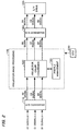
- FIG. 2 A functional block diagram of the image processing section within a conventional projector is shown in Fig. 2.
- This conventional projector inputs an R1 signal, a G1 signal, and a B1 signal (which form RGB signals in analog format, sent from a PC or the like) to an A/D converter section 110, and uses a projector image processing section 100 to perform color conversion on an R2 signal, a G2 signal, and a B2 signal that have been converted into digital form by the A/D converter section 110.
- An R3 signal, a G3 signal, and a B3 signal that have been subjected to the color conversion are input to a D/A converter section 180, and an R4 signal, a G4 signal, and a B4 signal that have been converted into analog form are input to a light valve (L/V) drive section 190, to drive a liquid-crystal light valve and thereby display an image.
- L/V light valve
- the projector image processing section 100 which is controlled by a CPU 200, comprises a projector color conversion section 120 and a profile management section 130.
- the projector color conversion section 120 converts the RGB digital signals (the R2 signal, G2 signal, and B2 signal) from the A/D converter section 110 into RGB digital signals for projector output (the R3 signal, G3 signal, and B3 signal), based on a projector input-output profiles that are managed by the profile management section 130.
- profile in this case refers to characteristic data.
- the conventional projector can only perform color conversion based on input-output profiles that indicate input-output characteristics which are specific to that particular projector, and thus no consideration is paid to the viewing environment in which the image is projected and displayed.
- the color appearance is detected by three factors: light, the reflection or transmission of light by objects, and vision.
- This embodiment of the present invention implements an image display system that can reproduce identical colors, by detecting the viewing environment of light as well as the reflection or transmission of that light by objects, irrespective of the environment in which it is used.
- the image appearance is also affected by the distance between the projector 20 and the screen 10. It is possible to measure the distance between the projector 20 and the screen 10 and correct the image from consideration of that distance, but the provision of a distance measurement means in addition to the image correction means would make the image display system itself much larger.
- images are corrected without having to provide a distance measurement means, by applying an image processing method that is not dependent on the distance between the projector 20 and the screen 10.
- the device is provided with a color light sensor 60 that functions as viewing environment detection means for detecting the viewing environment, as shown in Fig. 1, where viewing environment information from the color light sensor 60 is input to the projector 20.
- the color light sensor 60 measures viewing environment information (more specifically, RGB or XYZ tristimulus values) within the image display region 12 of the screen 10.
- the projector 20 is provided with brightness correction means, for correcting brightness information that is included in the viewing environment information to conform with the brightness of the ideal environment, based on the viewing environment information, if the image brightness in the viewing environment differs from the image brightness in the ideal environment; color difference calculation means for calculating color difference between color information included in the viewing environment information, in which the brightness information has been corrected and color information of an image in the ideal environment; and image correction means for correcting image display information that is used for displaying the image, based on the thus-calculated color difference.
- sequence of image processing for correcting the image is such that a white image is projected from the projector 20 to the screen 10 at each of predetermined gray scales and the viewing environment is detected by measuring tristimulus values of the image in the image display region 12 by the color light sensor 60.
- the correction of the image display information for each of those gray scales is based on those tristimulus values.
- FIG. 3 A functional block diagram of the image processing section within the projector 20 in accordance with an example of this embodiment is shown in Fig. 3.
- the projector 20 inputs the R1 signal, G1 signal, and B1 signal (which form RGB signals in analog format, sent from a PC or the like) to the A/D converter section 110, and the projector image processing section 100 performs color conversion on the digital R2 signal, G2 signal, and B2 signal.
- the projector 20 inputs the color-converted R3 signal, G3 signal, and B3 signal to the D/A converter section 180, then inputs the analog-converted R4 signal, G4 signal, and B4 signal to the light valve (L/V) drive section 190 which projects and displays an image by driving liquid-crystal light.valves.
- L/V light valve
- the projector image processing section 100 of the projector 20 in accordance with this embodiment comprises a color signal conversion section 160, a color signal reverse-conversion section 170, a color management section 150, and the projector color conversion section 120.
- the color signal conversion section 160 converts the digital RGB signals (R2 signal, G2 signal, and B2 signal) from the A/D converter section 110 into XYZ values (X1, Y1, Z1). Note that the colors represented by RGB signals are device-dependent colors that are affected by the input-output device, such as the projector 20, whereas the colors represented by the XYZ values are device-independent colors that are the same regardless of the device.
- the color signal conversion section 160 outputs the thus-converted XYZ values (X1, Y1, Z1) to the color management section 150.
- the color management section 150 converts the XYZ values (X1, Y1, Z1), which that have been input from the color signal conversion section 160, into XYZ values (X2, Y2, Z2) that take into account the viewing environment, based on a measured value from the color light sensor 60 that is the viewing environment detection means.
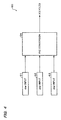
- FIG. 4 A functional block diagram of the color light sensor 60 in accordance with an example of this embodiment is shown in Fig. 4.
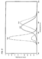
- a graph of color matching functions is shown in Fig. 5.
- the color light sensor 60 comprises an xbar input section 61, a ybar input section 62, and a zbar input section 63 that input the corresponding tristimulus values xbar, ybar, and zbar, of the color matching functions in the XYZ color system, as shown in Fig. 5.
- the color light sensor 60 also comprises an XYZ conversion section 64 that converts the xbar, ybar, and zbar values, which are input from the xbar input section 61, the ybar input section 62, and the zbar input section 63, into X3, Y3, and Z3 values.
- the color management section 150 also comprises a color light information processing section 140 and the profile management section 130 that manages the above described input-output profiles for the projector 20.
- FIG. 6 A functional block diagram of the color light information processing section 140 in accordance with an example of this embodiment is shown in Fig. 6.
- the color light information processing section 140 comprises a Y1x1y1 conversion section 141, which converts color signals (X1, Y1, Z1) in XYZ format for an ideal environment from the color signal conversion section 160 into color signals (Y1, x1, y1) in Yxy format; a Y3x3y3 conversion section 143, which converts color signals (X3, Y3, Z3) in XYZ format from the color light sensor 60 that represent the viewing environment into color signals (Y3, x3, y3) in Yxy format; and a Y replacing section 142 that functions as brightness correction means.
- the Y replacing section 142 replaces Y3 of the color signals (Y3, x3, y3) with Y1, based on Y1, which is part of the color signals from the color signal conversion section 160, and the color signals (Y3, x3, y3) from the Y3x3y3 conversion section 143.
- the color light information processing section 140 comprises a color difference correction calculation section 144 that calculates color difference and a tristimulus values conversion section 147 that converts color signals into tristimulus values (X2, Y2, Z2), based on the thus-calculated color difference.
- the color difference correction calculation section 144 comprises a color difference calculation section 145 and a Y2x2y2 conversion section 146.
- the color difference calculation section 145 calculates color difference between the color signals (Y1, x3, y3) from the Y replacing section 142 and the color signals (Y1, x1, y1) from the Y1x1y1 conversion section 141.
- FIG. 7 A schematic view of the color conversion in an xy chromaticity diagram is shown in Fig. 7.
- this ⁇ x and ⁇ y could be used as correction amounts for correcting the color of the image.
- the point indicating the color after the correction is denoted by a point P' (x2, y2).
- P' The point indicating the color after the correction.
- the Y2x2y2 conversion section 146 outputs values (x2, y2), which are obtained by correcting the ideal color (x1, y1) using ⁇ x and ⁇ y as correction amounts, together with Y2 to the tristimulus values conversion section 147. Note that the tristimulus values conversion section 147 uses Y1 as Y2 without modification.
- the tristimulus values conversion section 147 converts the color signals (Y2, x2, y2) from the Y2x2y2 conversion section 146 into tristimulus values (X2, Y2, Z2).
- the color light information processing section 140 outputs the tristimulus values (X2, Y2, Z2) from the tristimulus values conversion section 147 to the color signal reverse-conversion section 170.
- the profile management section 130 functions as the above described image correction means and creates the input-output profiles for the RGB signals of the projector 20. Note that each input-output profile is part of the information for image display used for displaying images.
- the profile management section 130 also manages the RGB input-output characteristics of the projector 20, using the thus-created input-output profiles for the RGB signals.
- the color signal reverse-conversion section 170 performs a reverse conversion on the XYZ values (X2, Y2, Z2) from the color light information processing section 140 to convert them into RGB digital signals (an R5 signal, a G5 signal, and a B5 signal), using a inverse matrix of the above-described matrix of the color signal conversion section 160.
- the projector color conversion section 120 converts the RGB digital signals (the R5 signal, G5 signal, and B5 signal) from the color signal reverse-conversion section 170 into the RGB digital signals (the R3 signal, G3 signal, and B3 signal) for projector output, with reference to projector profiles managed by the profile management section 130.
- the projector image processing section 100 that is controlled by the CPU 200 comprises the projector color conversion section 120 and the profile management section 130.
- the projector color conversion section 120 converts the RGB digital signals (the R6 signal, G6 signal, and B6 signal) from the A/D converter section 110 into the RGB digital signals for projector output (the R3 signal, G3 signal, and B3 signal), based on the input-output profiles for the RGB signals that are managed by the profile management section 130.
- the RGB digital signal for projector output that have been output from the projector color conversion section 120 are converted into the RGB analog signals (the R4 signal, G4 signal, and B4 signal) by the D/A converter section 180, and liquid-crystal light valves are driven by the L/V drive section 190 to project and display an image, based on those RGB analog signals.
- a presentation image that has been corrected in a manner that is appropriated for the viewing environment can be displayed, when image display information is corrected for each gray scales and the actual presentation image is displayed.
- This embodiment makes it possible to obtain color difference for color alone, excluding the brightness element, by correcting the brightness information that indicates the brightness of the image in the viewing environment to conform with the brightness in an ideal environment.
- the viewing environment information will be affected by the distance between the projector 20 and the screen 10. This means that the image will appear darker with distance.
- the brightness information (L value or Y value) included in the viewing environment information will vary with this distance.
- the color information within the viewing environment information will not, however, be affected by distance. In general, color has more effect than brightness on the image appearance.
- the image display information can be corrected rapidly irrespective of the distance between the color light sensor 60 and the image display region 12, as described above, it is possible to implement a system that ensures that the image appearance is substantially the same at a plurality of different locations, within a short period of time.
- the configuration could be implemented by an A/D converter or the like as the A/D converter section 110; a D/A converter or the like as the D/A converter section 180; a liquid-crystal light valve driver as the L/V drive section 406; an image processing circuit and ASIC or the like as the projector color conversion section 120, the color signal conversion section 160, the color signal reverse-conversion section 170, and the color light information processing section 140; and circuitry having a storage area such as RAM or the like as the profile management section 130.
- these components could be implemented in a hardware fashion by circuitry, or they could be implemented in a software fashion by drivers.
- the functions of the components could be implemented by reading out a program from an information storage medium 300, as shown in Fig. 3.
- the information storage medium 300 could be a CD-ROM, DVD-ROM, ROM, RAM, or HDD, by way of example, and the method of reading the program therefrom could be a direct method or an indirect method.
- the hardware described below may be employed for the color light sensor 60.
- the xbar input section 61, the ybar input section 62, and the zbar input section 63 may each be, for example, a color filter and photodiode that are selectively transparent with respect to the corresponding stimulus value
- the XYZ conversion section 64 may be, for example, an A/D converter that converts an analog signal from the photodiode into a digital signal and an op-amp that amplifies that digital signal.
- the tristimulus values that are input by the color light sensor 60 are not limited to xbar, ybar, and zbar values; they may equally well be XYZ values, RGB values, or rbar, gbar and bbar values that are color matching function values of RGB values, by way of example.
- the viewing environment detection means may be imaging means such as a CCD camera or a CMOS camera, instead of the color light sensor 60.
- the description of the embodying example above relates to an example of the correction of an image by the Yxy format, but it is equally possible to perform image correction by another type of representative format having brightness information and color information, such as the Lab format or Luv format. If the Lab format is used, by way of example, it is possible to correct the image by a method similar to the above described one, by reading Y as L and x and y as a and b.
- the above described screen 10 is of a reflective type but it may equally well be of a transparent type.
- the present invention may also be applied to presentations in which images are displayed by a display means other than a projection means such as the above described projector.
- this display means may be a cathode ray tube (CRT), a plasma display panel (PDP), a field emission display (FED), an electro- luminescence (EL) device, or a direct-view type liquid crystal display device, or a projector using a digital micromirror device (DMD), by way of example.
- DMD digital micromirror device
- the projector is not limited to a front-projection type device; it may equally well be of a rear-projection type.
- the time required for image correction may be shortened by the above described method of replacing brightness information, even when the present invention is applied to the above types of image display means.
- this invention is also effective in the display of images such as those at meetings, during medical treatment, in the design and fashion fields, business activities, commercials, and education, as well as general-purpose images such as those in movies, TV, videos, and games.
- the functions of the above-described projector image processing section 100 of the projector 20 could be implemented by a simgle image display device (such as the projector 20 itself) or by distribution between a plurality of processing devices (such as distributed processing between the projector 20 and a PC).
Landscapes
- Engineering & Computer Science (AREA)
- Multimedia (AREA)
- Signal Processing (AREA)
- Theoretical Computer Science (AREA)
- Computer Hardware Design (AREA)
- General Physics & Mathematics (AREA)
- Physics & Mathematics (AREA)
- Health & Medical Sciences (AREA)
- Biomedical Technology (AREA)
- General Health & Medical Sciences (AREA)
- Controls And Circuits For Display Device (AREA)
- Image Processing (AREA)
- Video Image Reproduction Devices For Color Tv Systems (AREA)
Abstract
Description
the brightness correction means may replace the L value or Y value of the viewing environment information with the L value or Y value of the image information for the ideal environment. This makes it possible to rapidly obtain a color difference between the color values x3 and y3 included in the viewing environment information and the color values x1 and y1 for the ideal environment, when an image is expressed in Yxy format, by way of example, by replacing the brightness value Y3 included in the viewing environment information with the brightness value Y1 for the ideal environment. Note that the image information may be an original image, by way of example.If a projector is used to project an image on a screen, for example, the viewing environment information will be affected by the distance between the projector and the screen. This means that the image will appear darker with distance. In other words, the brightness information (L value or Y value) included in the viewing environment information will vary depending on the distance. The color information in the viewing environment information will not, however, be affected by the distance. In general, color has more effect than brightness on the image appearance.In other words, there is little effect on the image appearance, even when the brightness value included in the viewing environment information is replaced with the brightness value for the ideal environment. It is therefore possible to adjust the image appearance as appropriate, without having to detect the viewing environment again, even if the distance between the display area of the image (such as a screen) and the viewing environment detection means has changed. This makes it possible to implement an image display system that enables corrections of the image appearance, within a short time.
the color difference detection step may comprise:
the brightness correction step may comprise a step of replacing the L value or Y value of the viewing environment information with the L value or Y value of the image information for the ideal environment. This makes it possible to rapidly obtain the color values x3 and y3 included in the viewing environment information and the color values x1 and y1 for the ideal environment, when an image is expressed in Yxy format, by way of example, by replacing the brightness value Y3 included in the viewing environment information with the brightness value Y1 for the ideal environment.
the color difference detection means may comprise:
the brightness correction means may replace the L value or Y value of the viewing environment information with the L value or Y value of the image information for the ideal environment.
Claims (11)
- An image display system of environment-compliant type which corrects image display information for displaying an image and displays the image, based on viewing environment information obtained by viewing environment detection means which detects a viewing environment in a display area of the image; the image display system comprising:brightness correction means for correcting brightness information included in the viewing environment information to conform with brightness of an ideal environment, based on the viewing environment information, when brightness of the image in the viewing environment differs from brightness of the image in the ideal environment;color difference calculation means for calculating color difference between color information included in the viewing environment information, in which the brightness information has been corrected, and color information of the image in the ideal environment; andimage correction means for correcting the image display information, based on the calculated color difference.
- The image display system as defined in claim 1,
wherein the viewing environment detection means measures tristimulus values of an image in the display area or captures an image in the display area. - The image display system as defined in claim 2, comprising a front-projection type image projection device including:the brightness correction means;the color difference calculation means;the image correction means; andmeans which projects a corrected image towards the display area.
- The image display system as defined in claim 3,
wherein image information for the ideal environment and the viewing environment information are expressed in Lab format or Yxy format; and
wherein the brightness correction means replaces the L value or Y value of the viewing environment information with the L value or Y value of the image information for the ideal environment. - An image display system of environment-compliant type which corrects image display information for displaying an image and displays the image, based on viewing environment information obtained by viewing environment detection means which detects a viewing environment in a display area of the image; the image display system comprising:a brightness correction section which corrects brightness information included in the viewing environment information to conform with brightness of an ideal environment, based on the viewing environment information, when brightness of the image in the viewing environment differs from brightness of the image in the ideal environment;a color difference calculation section which calculates color difference between color information included in the viewing environment information, in which the brightness information has been corrected, and color information of the image in the ideal environment; andan image correction section which corrects the image display information, based on the calculated color difference.
- An image processing method of environment-compliant type which corrects image display information for displaying an image, based on viewing environment information indicating a viewing environment in a display area of the image, the image processing method comprising:a step of generating the viewing environment information;a color difference detection step of detecting color difference between a given image in the viewing environment and the given image in an ideal environment, based on the generated viewing environment information; anda step of correcting the image display information, based on the detected color difference.
- The image processing method as defined in claim 6,
wherein the viewing environment information comprises color information indicating color of the image in the viewing environment and brightness information indicating brightness of the image in the viewing environment; and
wherein the color difference detection step comprises:a brightness correction step which corrects brightness information included in the viewing environment information to conform with brightness of the ideal environment, based on the viewing environment information, when brightness of the image in the viewing environment differs from brightness of the image in the ideal environment; anda step of calculating the color difference based on color information included in the viewing environment information, in which the brightness information has been corrected, and color information of the image in the ideal environment. - The image processing method as defined in claim 7,
wherein image information for the ideal environment and the viewing environment information are expressed in Lab format or Yxy format; and
wherein the brightness correction step comprises a step of replacing the L value or Y value of the viewing environment information with the L value or Y value of the image information for the ideal environment. - A computer-readable information storage medium which stores program for correcting image display information for displaying an image, based on viewing environment information indicating a viewing environment in a display area of the image, the information storage medium comprising program to implement on a computer:means which generates the viewing environment information;color difference detection means which detects color difference between a given image in the viewing environment and the given image in an ideal environment, based on the generated viewing environment information; andmeans which corrects the image display information, based on the detected color difference.
- The information storage medium as defined in claim 9,
wherein the viewing environment information comprises color information indicating color of the image in the viewing environment and brightness information indicating brightness of the image in the viewing environment; and
wherein the color difference detection means comprises:brightness correction means which corrects brightness information included in the viewing environment information to conform with brightness in the ideal environment, based on the viewing environment information, when brightness of the image in the viewing environment differs from brightness of the image in the ideal environment; andmeans which calculates the color difference based on color information included in the viewing environment information, in which the brightness information has been corrected, and color information of the image in the ideal environment. - The information storage medium as defined in claim 10,
wherein image information for the ideal environment and the viewing environment information are expressed in Lab format or Yxy format; and
wherein the brightness correction means replaces the L value or Y value of the viewing environment information with the L value or Y value of the image information for the ideal environment.
Applications Claiming Priority (3)
| Application Number | Priority Date | Filing Date | Title |
|---|---|---|---|
| JP2000257159 | 2000-08-28 | ||
| JP2000257159A JP3744778B2 (en) | 2000-08-28 | 2000-08-28 | Image projection apparatus, image processing method, and information storage medium |
| PCT/JP2001/007375 WO2002019306A1 (en) | 2000-08-28 | 2001-08-28 | Environment compatible image display system, image processing method and information storing medium |
Publications (2)
| Publication Number | Publication Date |
|---|---|
| EP1265218A1 true EP1265218A1 (en) | 2002-12-11 |
| EP1265218A4 EP1265218A4 (en) | 2004-05-06 |
Family
ID=18745668
Family Applications (1)
| Application Number | Title | Priority Date | Filing Date |
|---|---|---|---|
| EP01958567A Ceased EP1265218A4 (en) | 2000-08-28 | 2001-08-28 | ENVIRONMENTALLY COMPATIBLE IMAGE DISPLAY SYSTEM, IMAGE PROCESSING METHOD, AND INFORMATION STORAGE MEDIUM |
Country Status (5)
| Country | Link |
|---|---|
| US (1) | US7345692B2 (en) |
| EP (1) | EP1265218A4 (en) |
| JP (1) | JP3744778B2 (en) |
| CN (1) | CN1168065C (en) |
| WO (1) | WO2002019306A1 (en) |
Families Citing this family (36)
| Publication number | Priority date | Publication date | Assignee | Title |
|---|---|---|---|---|
| JP3729252B2 (en) * | 2001-03-26 | 2005-12-21 | セイコーエプソン株式会社 | Image processing system, program, and information storage medium |
| JP3719411B2 (en) * | 2001-05-31 | 2005-11-24 | セイコーエプソン株式会社 | Image display system, projector, program, information storage medium, and image processing method |
| US7391475B2 (en) * | 2002-01-31 | 2008-06-24 | Hewlett-Packard Development Company, L.P. | Display image generation with differential illumination |
| DE50311550D1 (en) * | 2003-06-23 | 2009-07-09 | Logo Beteiligungsges Mbh | Method for outputting a digital document from a color management-less application on an output device, with color correction by means of an additional program module |
| KR100499149B1 (en) * | 2003-06-30 | 2005-07-04 | 삼성전자주식회사 | Method for visual measurement of the lightness characteristic of the ambient light source of a display |
| DE102004010710B4 (en) * | 2004-03-04 | 2006-06-08 | Siemens Ag | Method for operating a mobile device for the projection of image data and mobile projector device |
| EP2427011B1 (en) * | 2004-10-15 | 2014-08-27 | Apple Inc. | Communication Resource Allocation Methods |
| KR100640063B1 (en) * | 2005-02-18 | 2006-10-31 | 삼성전자주식회사 | Image Enhancement Method and Apparatus Considering External Illumination |
| KR100710302B1 (en) * | 2005-05-17 | 2007-04-23 | 엘지전자 주식회사 | Apparatus and method for color correction of a display device |
| CN101512630B (en) * | 2006-08-29 | 2011-06-22 | 松下电器产业株式会社 | Image display method and image display device |
| CN101578855B (en) * | 2008-08-28 | 2015-07-29 | 香港应用科技研究院有限公司 | digital image enhancement |
| US20100251293A1 (en) * | 2009-03-31 | 2010-09-30 | Canon Kabushiki Kaisha | Network streaming of a video media from a media server to a media client |
| US8510462B2 (en) * | 2009-03-31 | 2013-08-13 | Canon Kabushiki Kaisha | Network streaming of a video media from a media server to a media client |
| US8745186B2 (en) * | 2009-03-31 | 2014-06-03 | Canon Kabushiki Kaisha | Network streaming of a video media from a media server to a media client |
| CN101976540B (en) * | 2010-11-22 | 2012-10-03 | 天津三星电子有限公司 | Method for automatically adjusting grey-scale consistency of display |
| US20120182276A1 (en) * | 2011-01-19 | 2012-07-19 | Broadcom Corporation | Automatic adjustment of display systems based on light at viewer position |
| CN103295560B (en) * | 2012-02-24 | 2016-01-27 | 联想(北京)有限公司 | terminal device and display adjusting method thereof |
| US8836910B2 (en) * | 2012-06-04 | 2014-09-16 | James A. Cashin | Light and sound monitor |
| DE102013206832A1 (en) * | 2013-04-16 | 2014-10-16 | Robert Bosch Gmbh | IMAGE DISPLAY DEVICE, MOBILE PHONE AND METHOD |
| CN105100761A (en) * | 2015-07-09 | 2015-11-25 | 西安电子科技大学 | Image display method |
| CN105096910B (en) * | 2015-07-09 | 2018-02-16 | 西安诺瓦电子科技有限公司 | Image processing method |
| US10667723B2 (en) * | 2016-02-19 | 2020-06-02 | Covidien Lp | Systems and methods for video-based monitoring of vital signs |
| JP6919485B2 (en) * | 2017-10-10 | 2021-08-18 | 京セラドキュメントソリューションズ株式会社 | Image output control device, image output control method, image output system and image output control program |
| WO2019094893A1 (en) | 2017-11-13 | 2019-05-16 | Covidien Lp | Systems and methods for video-based monitoring of a patient |
| CN111565638B (en) | 2018-01-08 | 2023-08-15 | 柯惠有限合伙公司 | System and method for video-based non-contact tidal volume monitoring |
| US11510584B2 (en) | 2018-06-15 | 2022-11-29 | Covidien Lp | Systems and methods for video-based patient monitoring during surgery |
| WO2020033613A1 (en) | 2018-08-09 | 2020-02-13 | Covidien Lp | Video-based patient monitoring systems and associated methods for detecting and monitoring breathing |
| US11617520B2 (en) | 2018-12-14 | 2023-04-04 | Covidien Lp | Depth sensing visualization modes for non-contact monitoring |
| US11315275B2 (en) | 2019-01-28 | 2022-04-26 | Covidien Lp | Edge handling methods for associated depth sensing camera devices, systems, and methods |
| US12357194B2 (en) | 2020-07-09 | 2025-07-15 | Covidien Lp | Informative display for non-contact patient monitoring |
| US12514468B2 (en) | 2020-12-02 | 2026-01-06 | Covidien Lp | Patient position monitoring methods and systems |
| US12390124B2 (en) | 2021-01-27 | 2025-08-19 | Covidien Lp | Systems and methods for non-contact respiratory monitoring |
| US12490904B2 (en) | 2021-10-08 | 2025-12-09 | Covidien Lp | Enhanced image for non-contact monitoring |
| US12482557B2 (en) | 2021-12-09 | 2025-11-25 | Covidien Lp | Systems and methods for improved non-contact patient monitoring of incubated neonates |
| US12374128B2 (en) | 2021-12-21 | 2025-07-29 | Covidien Lp | Non-contact depth sensing monitoring in vehicles |
| JP2024146490A (en) * | 2023-03-31 | 2024-10-15 | 富士フイルム株式会社 | CONTROL DEVICE, PHOTOGRAPHY SYSTEM, CONTROL METHOD, AND CONTROL PROGRAM |
Family Cites Families (29)
| Publication number | Priority date | Publication date | Assignee | Title |
|---|---|---|---|---|
| US4875032A (en) * | 1987-10-26 | 1989-10-17 | Mcmanus Paul A | Method and apparatus for processing colorimetric parameters of a color sample |
| US5258828A (en) * | 1989-11-13 | 1993-11-02 | Hitachi, Ltd. | Color CRT drive apparatus having automatic white balance adjusting circuit and CRT display |
| JPH0425892A (en) | 1990-05-21 | 1992-01-29 | Canon Inc | Image processor |
| JP2973477B2 (en) | 1990-06-20 | 1999-11-08 | ソニー株式会社 | Projector with correction circuit |
| JP2567756B2 (en) | 1991-07-04 | 1996-12-25 | 三洋電機株式会社 | Image automatic control display device for television receiver |
| JPH05127620A (en) * | 1991-11-06 | 1993-05-25 | Matsushita Electric Ind Co Ltd | Method and circuit for adjusting liquid crystal projection type color display |
| JP3083918B2 (en) * | 1992-06-26 | 2000-09-04 | 本田技研工業株式会社 | Image processing device |
| US6081254A (en) * | 1993-08-12 | 2000-06-27 | Hitachi, Ltd. | Color correction system of imaging apparatus |
| JP3346000B2 (en) | 1993-12-10 | 2002-11-18 | 株式会社日立製作所 | Color reproduction system and sales system |
| JPH07231394A (en) | 1994-02-17 | 1995-08-29 | Canon Inc | Method for creating color correction signal, color image display method using the same, apparatus therefor, and color image colorimetry method and apparatus therefor |
| EP0683596B1 (en) * | 1994-05-18 | 2000-08-30 | Sharp Kabushiki Kaisha | Card type camera with image processing function |
| JP2907057B2 (en) | 1995-04-20 | 1999-06-21 | 日本電気株式会社 | Brightness automatic adjustment device |
| US5737032A (en) * | 1995-09-05 | 1998-04-07 | Videotek, Inc. | Serial digital video processing with concurrent adjustment in RGB and luminance/color difference |
| KR100355378B1 (en) * | 1996-01-15 | 2002-12-26 | 삼성전자 주식회사 | Color image display method under various illumination light |
| US5818597A (en) * | 1996-10-22 | 1998-10-06 | Ultra Stereo Labs, Inc. | Projection system visual characteristics analyzer |
| US6388648B1 (en) * | 1996-11-05 | 2002-05-14 | Clarity Visual Systems, Inc. | Color gamut and luminance matching techniques for image display systems |
| US5803570A (en) * | 1996-12-10 | 1998-09-08 | Raytheon Company | Calibration system and method for display optical systems |
| JPH10174017A (en) | 1996-12-16 | 1998-06-26 | Mitsubishi Electric Corp | Television receiver and color temperature control method thereof |
| DE69835638T2 (en) * | 1997-07-09 | 2006-12-28 | Canon K.K. | Color image processing apparatus and method |
| DE19743551C1 (en) * | 1997-10-01 | 1999-02-11 | Siemens Ag | Data value acquisition for mouse pointer on computer display |
| GB2335326B (en) * | 1997-10-31 | 2002-04-17 | Sony Corp | Image processing apparatus and method and providing medium. |
| US6411306B1 (en) * | 1997-11-14 | 2002-06-25 | Eastman Kodak Company | Automatic luminance and contrast adustment for display device |
| JP3029254B2 (en) | 1998-02-12 | 2000-04-04 | リコー計器株式会社 | Control device for liquid crystal display |
| KR100299759B1 (en) | 1998-06-29 | 2001-10-27 | 구자홍 | Automatic display device and method of video display device |
| JP2001060082A (en) | 1999-08-24 | 2001-03-06 | Matsushita Electric Ind Co Ltd | Color reproduction terminal device and network color reproduction system |
| US6807301B1 (en) * | 2000-02-25 | 2004-10-19 | Fujitsu Limited | Image production controlling device, image producing device, image production controlling method, and a storage medium |
| US6961461B2 (en) * | 2000-05-17 | 2005-11-01 | Tidal Photonics, Inc. | Apparatus and method for measurement, encoding and displaying of object color for digital imaging |
| JP3707371B2 (en) * | 2000-08-28 | 2005-10-19 | セイコーエプソン株式会社 | Image display system, image processing method, and information storage medium |
| JP3894302B2 (en) * | 2002-03-25 | 2007-03-22 | セイコーエプソン株式会社 | Image display system, image processing method, program, and information storage medium |
-
2000
- 2000-08-28 JP JP2000257159A patent/JP3744778B2/en not_active Expired - Fee Related
-
2001
- 2001-08-28 CN CNB018033628A patent/CN1168065C/en not_active Expired - Fee Related
- 2001-08-28 EP EP01958567A patent/EP1265218A4/en not_active Ceased
- 2001-08-28 WO PCT/JP2001/007375 patent/WO2002019306A1/en not_active Ceased
- 2001-08-28 US US10/111,323 patent/US7345692B2/en not_active Expired - Fee Related
Also Published As
| Publication number | Publication date |
|---|---|
| US20020171766A1 (en) | 2002-11-21 |
| EP1265218A4 (en) | 2004-05-06 |
| CN1394328A (en) | 2003-01-29 |
| JP3744778B2 (en) | 2006-02-15 |
| US7345692B2 (en) | 2008-03-18 |
| JP2002074349A (en) | 2002-03-15 |
| WO2002019306A1 (en) | 2002-03-07 |
| CN1168065C (en) | 2004-09-22 |
Similar Documents
| Publication | Publication Date | Title |
|---|---|---|
| US7345692B2 (en) | Environment-compliant image display system and image processing method | |
| US7542055B2 (en) | Image display system, projector, information storage medium, and image processing method | |
| US6927784B2 (en) | Image display system, projector, program, information storage medium, and image processing method | |
| EP1265219B1 (en) | Environment adaptive image display system, image processing method and information storing medium | |
| US6894697B2 (en) | Environment-compliant image display system and program | |
| JP3894302B2 (en) | Image display system, image processing method, program, and information storage medium | |
| JP5354265B2 (en) | Liquid crystal display | |
| EP1205902B1 (en) | Image display system, image processing method, and information storage medium | |
| US20030020725A1 (en) | Environment-compliant image display system, projector, and program | |
| EP1370092A1 (en) | Environment-adaptive image display system, information storage medium, and image processing method | |
| US20030011563A1 (en) | Image displaying system of environment-adaptive type, presentation system, and image processing method and program | |
| JPWO2002019307A1 (en) | Environmentally adaptive image display system, image processing method, and information storage medium | |
| JPWO2003001499A1 (en) | Image display system, projector, image processing method, and information storage medium | |
| CN101674443A (en) | A method for color correction of a projector | |
| US6940531B2 (en) | Environment-Compliant image display system, image processing method, and information storage medium | |
| JP2004004808A (en) | Image display system and information storage medium |
Legal Events
| Date | Code | Title | Description |
|---|---|---|---|
| PUAI | Public reference made under article 153(3) epc to a published international application that has entered the european phase |
Free format text: ORIGINAL CODE: 0009012 |
|
| 17P | Request for examination filed |
Effective date: 20020620 |
|
| AK | Designated contracting states |
Kind code of ref document: A1 Designated state(s): AT BE CH CY DE DK ES FI FR GB GR IE IT LI LU MC NL PT SE TR |
|
| A4 | Supplementary search report drawn up and despatched |
Effective date: 20040319 |
|
| RIC1 | Information provided on ipc code assigned before grant |
Ipc: 7H 04N 9/31 B Ipc: 7H 04N 17/02 B Ipc: 7H 04N 5/58 B Ipc: 7G 09G 5/00 A Ipc: 7G 09G 5/02 B Ipc: 7H 04N 9/64 B Ipc: 7H 04N 9/73 B Ipc: 7H 04N 5/74 B |
|
| RBV | Designated contracting states (corrected) |
Designated state(s): AT BE CH DE FR GB LI |
|
| 17Q | First examination report despatched |
Effective date: 20070718 |
|
| STAA | Information on the status of an ep patent application or granted ep patent |
Free format text: STATUS: THE APPLICATION HAS BEEN REFUSED |
|
| 18R | Application refused |
Effective date: 20090709 |